EP0707101A2 - Dispositif d'insertion de la trame dans la foule d'un métier à jet d'air - Google Patents
Dispositif d'insertion de la trame dans la foule d'un métier à jet d'air Download PDFInfo
- Publication number
- EP0707101A2 EP0707101A2 EP95115223A EP95115223A EP0707101A2 EP 0707101 A2 EP0707101 A2 EP 0707101A2 EP 95115223 A EP95115223 A EP 95115223A EP 95115223 A EP95115223 A EP 95115223A EP 0707101 A2 EP0707101 A2 EP 0707101A2
- Authority
- EP
- European Patent Office
- Prior art keywords
- air
- air duct
- shed
- weft
- angle
- Prior art date
- Legal status (The legal status is an assumption and is not a legal conclusion. Google has not performed a legal analysis and makes no representation as to the accuracy of the status listed.)
- Withdrawn
Links
Images


Classifications
-
- D—TEXTILES; PAPER
- D03—WEAVING
- D03D—WOVEN FABRICS; METHODS OF WEAVING; LOOMS
- D03D47/00—Looms in which bulk supply of weft does not pass through shed, e.g. shuttleless looms, gripper shuttle looms, dummy shuttle looms
- D03D47/28—Looms in which bulk supply of weft does not pass through shed, e.g. shuttleless looms, gripper shuttle looms, dummy shuttle looms wherein the weft itself is projected into the shed
- D03D47/30—Looms in which bulk supply of weft does not pass through shed, e.g. shuttleless looms, gripper shuttle looms, dummy shuttle looms wherein the weft itself is projected into the shed by gas jet
- D03D47/3066—Control or handling of the weft at or after arrival
- D03D47/308—Stretching or holding the weft
-
- D—TEXTILES; PAPER
- D03—WEAVING
- D03D—WOVEN FABRICS; METHODS OF WEAVING; LOOMS
- D03D47/00—Looms in which bulk supply of weft does not pass through shed, e.g. shuttleless looms, gripper shuttle looms, dummy shuttle looms
- D03D47/28—Looms in which bulk supply of weft does not pass through shed, e.g. shuttleless looms, gripper shuttle looms, dummy shuttle looms wherein the weft itself is projected into the shed
- D03D47/30—Looms in which bulk supply of weft does not pass through shed, e.g. shuttleless looms, gripper shuttle looms, dummy shuttle looms wherein the weft itself is projected into the shed by gas jet
- D03D47/3006—Construction of the nozzles
- D03D47/302—Auxiliary nozzles
Definitions
- the invention relates to a device for inserting the weft thread into the shed of an air jet loom connected to a compressed air source, with a sley that can be moved back and forth transversely to the insertion direction of the weft thread, a reed provided on the fabric side with a first air channel and a number spaced apart from one another arranged on the sley and depending on the movement in the shed and again extractable and in connection with the compressed air source connected to the nozzle body, wherein in the first air duct from the individual nozzle bodies, each provided with an outlet opening, pressurized with compressed air transported through the shed through means arranged on the outlet side is held.
- Air jet weaving machines in which the weft thread is inserted or shot into the shed by means of a compressed air jet emitted by a high-pressure nozzle and when inserted by means of a plurality of spaced apart ones in the entry direction and immersed in the shed and extractable nozzle body is additionally acted upon by compressed air are generally known.
- the individual nozzle bodies require a relatively large amount of air due to their design and the arrangement of the outlet opening, and especially when immersed in the shed, they are often deformed by the relatively closely spaced warp threads in such a way that after a relatively short operating time the Damaged nozzle body to avoid damage to the warp threads, etc. must be replaced by a relatively time-consuming and costly assembly.
- Another disadvantage is that the weft thread end must be dimensioned relatively long so that it can be gripped and held securely up to the fabric-side stop, the weft thread end being cut off on the outlet side in a manner known per se.
- the invention has for its object to improve a device of the generic type in such a way that, due to an advantageous configuration of the individual nozzle bodies, trouble-free immersion and removal of the same and sufficient pressurized air pressure on the weft thread over the entire shed width is ensured, and due to further means an exact hold of the exit-side weft end is reached until the weft thread stops on the fabric side.
- the individual nozzle body be provided with a nozzle part which is elliptical in profile cross section and closed by a head part assigned to the shed in the form of a tip and which has at least one outlet opening on one wall part facing the first air duct, the outlet opening with respect to its central axis on the one hand at a first angle oriented obliquely upwards in the direction of the first air duct and on the other hand at an in
- the weft direction is arranged in the plane of the laterally oriented second angle in the wall part of the nozzle part, and that on the outlet side a guide member corresponding to the first air duct is provided, which has a second air duct corresponding to the first air duct, in which the weft thread end is acted upon by an additional compressed air jet until tissue-side stop is held in an extended position.
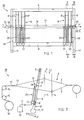
- FIG. 1 shows a schematic and in view view of a sley 10 for an air jet weaving machine, designated as a whole with 20, with the essential functional elements for the pneumatic entry, transport and holding of the weft thread 18 to be inserted into a shed 12 (FIG. 2/3).
- loom 20 For simplification the air jet loom will be referred to as loom 20 hereinafter.
- the sley 10 essentially comprises two vertical side bars 11 and 11 'arranged at a distance from one another, two transverse bars arranged thereon in a vertical direction at a distance from one another and fastened in a manner not shown 9 and 9 'as well as reeds 8' arranged at a distance from each other, which are fastened to the cross bars 9, 9 'in a manner not shown.
- the reeds 8 'each provided with a recess 7 (FIG. 2) together form a weaving comb or reed 8 oriented over the entire width of the sley 10.
- the recesses 7 on the individual reeds 8' together form one shown schematically in FIG Guide channel 19 for the weft thread 18.
- the reed 8 which extends over the entire width of the sley 10, is only partially shown in the two outer regions of the sley 10.
- FIG. 1 a high-pressure nozzle 75, assigned and schematically shown in the area of the entry side E of the sley 10, for the air jet (not shown) oriented in the direction of the arrow Y for the insertion of the weft thread 18 into the shed 12 (FIG. 2).
- the device 50 provided with a guide member 60 for holding the weft end 18 'emerging laterally in the direction of the arrow Y' is arranged in the region of the sley 10 on the opposite discharge side E '.
- the device 50 arranged on the sley 10 in the region of the discharge side E ' is fastened to the lower cross member 9' in a manner not shown with a supporting part 65.
- the reeds 8 'of the reed 8, which are arranged at a distance from one another, are assigned individual nozzle elements 25.
- the nozzle elements 25 arranged over the entire width of the sley 10 are each exchangeably fastened to the lower cross member 9 'by means not shown.
- the nozzle elements 25 arranged in series are each provided with one or more outlet openings (not shown) at the upper end.
- the outlet openings are designed and in each case arranged at the upper end of the nozzle body 25 in such a way that the weft thread 18 shot into the guide channel 19 of the reed 8 passes over the entire width of the sley 10, that is, from the entry side E to the discharge side E 'can also be acted upon with compressed air.
- the nozzle bodies 25 arranged in a row, as shown schematically in FIG. 2, are connected to an associated compressed air source 70 via a line 71 connected to a holding piece 17 in a manner not shown.
- the nozzle body 25 which is arranged at a distance from one another over the entire width of the sley 10, the weft thread 18 is transported through the guide channel 19 in an exactly stretched position.
- FIG. 2 shows the weaving machine 20 as a schematic diagram and the essential functional elements for the formation of the shed 12 can be seen.
- warp threads 2 and 3 drawn off from a schematically illustrated storage device 1 are used to form the shed 12 in a manner known per se by correspondingly arranged and designed heald frames 4 and 5 alternately raised or lowered in the direction of the arrow Z or Z '.
- the heald frames 4 and 5 are provided with separate healds (not shown) for the separate passage of the individual warp threads 2 and 3, the heald frames 4 and 5 as well as the healds together forming a weaving harness designated as a whole by 6.
- the sley 10 which can be moved back and forth in the direction of the arrows X and X '(not shown).
- the sley 10 formed as a frame comprises the side rails 11 and 11' (FIG. 1) arranged at a distance from one another and the two attached to it and the two side rails 11 and 11 'connecting cross bars 9 and 9'.
- the weft thread 18 is drawn off in a manner known per se from a supply spool (not shown) and inserted (shot in) into the guide channel 19 by means of the high-pressure nozzle 75 (FIG. 1) arranged on the side of the sley 10.
- the weft thread 18 inserted in the guide channel 19 is additionally supplied with compressed air through the shed 12 by means of the nozzle elements 25 arranged in series and struck by the reed 8 moved in the direction of the arrow X against a fabric 13 shown schematically in FIG. In this phase, the weft thread 18 is woven into the fabric 13.
- the individual nozzle elements 25 are arranged on the lower cross member 9 'of the sley 10 and fastened with means (not shown) such that they dip into the shed 12 when the sley 19 moves in the direction of the arrow X.
- the special design of the individual nozzle element 25 will be described in detail later in connection with FIGS. 4 to 8.
- the sley 10 with the reed 8 is moved in the direction of the arrow X ', so that the individual nozzle elements 25 (FIG. 2) arranged in series on the cross member 9' are pulled out of the shed 12 again become.
- a so-called shed change of the individual warp threads 2 and 3 is carried out for the formation of a next shed 12 for the next entry of the weft thread 18 by actuating the heald frames 4 and 5 in the direction of arrows Z and Z '.
- the individual nozzle bodies 25, as shown schematically in FIGS. 1 and 2 are each arranged interchangeably in the holding piece 17.
- the holding pieces connected via a line 71 to a compressed air source 70, which is shown schematically in FIG 17 for the nozzle elements 25 are preferably exchangeably attached to the lower cross member 9 'of the sley 10.
- the movements of the heald frames 4 and 5 oriented in the direction of the arrows Z and Z 'and the movements of the sley 10 with the reed 8 oriented in the direction of the arrows X and X' are carried out in a manner known per se by means of drive means (not shown).
- the fabric 13 formed by the individual functions described above is, for example, as shown schematically in FIG. 2 and FIG. 3, passed over a first and a second goods take-off tree 14 and 15 and wound onto a goods tree 16 rotatably driven about its longitudinal axis.
- the goods take-off trees 14, 15, which are operatively connected to drive means (not shown), and the goods tree 16 provided for receiving the fabric 13 are not the subject of this invention and are therefore shown only schematically.
- FIG. 3 shows the weaving machine 20 along the line III-III in FIG. 1 as a further schematic diagram and one recognizes the functional elements 1 to 10 and 65 and 70 and 70 etc. described above in connection with FIG. 2 for the shed and Tissue formation.
- FIG. 3 shows the device 50 which is fastened to the sley 10 on the outlet side (FIG. 1) by means of a supporting part 65 and by means of which the weft thread end 18 '(FIG. 1) is held in an extended position.
- a line 71 ' which is connected to the schematically illustrated compressed air source 70, is connected to the support part 65 of the device 50.
- the device 50 for holding the weft thread end 18 ' is described in more detail below in connection with FIGS. 9 to 11.
- the nozzle body 25 comprises a first section 30, a second section 35 formed thereon and an integrally formed thereon third section 40, the third section 40 hereinafter being referred to as nozzle part 40.
- the second section 35 which tapers conically by mechanical deformation (pressing together) in the direction of the nozzle part 40, is formed on the first cylindrical section 30.
- the nozzle part 40 which is compressed approximately in an ellipse (FIG. 8), adjoins the second section 35.
- the nozzle part 40 is closed by an integrally formed head part 45, which is designed approximately as a projectile-shaped tapered tip 46.
- At least one outlet opening 43 is provided on the side of the head part 45 of the nozzle body 25.
- the nozzle body 25 is shown in a view according to the arrow direction K ′′ drawn in FIG. 2 and the cylindrical first section 30 can be seen, the second section 35 which widens conically in the direction of the nozzle part 40 in this view, as well as that in the latter View due to the mechanical deformation larger than the first cylindrical section 30 formed nozzle part 40.
- the outlet opening 43 is provided in the upper region of the nozzle part 40, which is in communication with the interior 25 '(FIG. 6) of the nozzle body 25.
- the special design of the individual sections 30, 35, 40 and 45 of the nozzle body 25, as well as the arrangement of the outlet opening 43 provided in the nozzle part 40 and the special design of the head part 45 are described in detail below in connection with FIGS. 6 to 8.
- FIG. 6 shows a section of the nozzle body 25, shown partially in section, on a larger scale and in FIG. 4 by a circle K, and the first cylindrical section 30 provided with a first passage channel 29 can be seen, which has a conically tapering in this view second passage 35 provided second section 35 and the nozzle part 40 provided with a third passage 39.
- the nozzle part 40 is at its upper End closed by the integrally formed and essentially hood-shaped head part 45.
- the channels 29, 34 and 39 which are oriented in the axial direction of the nozzle body 25 and at one end delimited by the head part 45, are connected to one another and together form the interior 25 'of the nozzle body 25.
- the nozzle part 40 which is largely elliptical in profile, has a first one arcuate side wall 41 (FIG. 8) and a second arcuate side wall 42 (FIG. 8) formed thereon, the two side walls 41, 42 being connected to one another in the outer region by a bend 47 and 47 '(FIG. 8).
- At least one outlet opening 43 which is connected to the passage channels 29, 34 and 39 of the sections 30, 35 and 40, is arranged in the second side wall 42.
- the outlet opening 43 arranged centrally on an imaginary central axis M is arranged at a distance C from the tip 46 of the head piece 45.
- the distance C is selected such that a chamber 44 is formed between the inside 45 'of the head piece 45 and the inside surface 43' of the, for example, circular outlet opening 43.
- the chamber 44 which is designed approximately as a semicircular ring and, as shown schematically in FIG. 7, surrounds the outlet opening 43, essentially serves to deflect the air jet (not shown) directed into the interior 25 'of the nozzle body 25 and against the inside 45' of the head piece 45.
- the outlet opening 43 arranged in the second side wall 42 of the head part 45 is, as shown in FIG imaginary center axis M directed obliquely upwards at a first angle ⁇ in the direction of the tip 46 of the head part 45 and, on the other hand, as shown in the plan view according to FIG. 8, with respect to the imaginary axis of symmetry S of the nozzle body 25 arranged in the plane in the direction of the weft thread 18 at a second angle ⁇ 'in the second side wall 42.
- the outlet opening 43 has a diameter of 1.5 mm, for example.
- the first angle ⁇ of the outlet opening 43 oriented obliquely upwards with respect to the imaginary central axis M is approximately in the order of 8 ° to 15 °.
- the length B, oriented in the axial direction, of the nozzle part 40 which is elliptical in profile cross section (FIG. 8), is approximately 5 times the length A, oriented in the axial direction, of the central, conically tapering second section 35
- the length A is approximately 3 mm and the length B is approximately 15 mm.
- the length C extending from the imaginary central axis M of the outlet opening 43 to the head part 45 is, for example, 2 mm.
- the individual nozzle body 25 is preferably made of a stainless steel, which is preferably relatively easy to deform.
- the outer circumferential surface of the elliptically shaped nozzle part 40, but preferably the entire nozzle body 25, is completely ground after the individual shaping and processing operations, so that the outer shape of the nozzle body has an absolutely smooth surface.
- the second side wall 42 it is also possible to arrange a plurality of outlet openings 43 which are arranged in mutually distributed formations and which penetrate the second side wall 42.
- the individual outlet openings 43 are corresponding to the above described and arranged in relation to the imaginary central axis M (FIG. 6) and to the axis of symmetry S (FIG. 8) in the second side wall 42.
- the diameter of the respective outlet opening 43 is preferably on the order of 1.0 mm to 2.0 mm. If several outlet openings are arranged, they are correspondingly smaller in diameter.
- the two side walls 41 and 42 of the nozzle part 40 are each provided with a wall part 41 ′ and 42 ′ that is inclined in the direction of the tip 46 of the head part 45.
- One wall part 41 ' is with respect to the first vertical side wall 41 at a first angle of inclination ⁇ in the order of about 15 ° to 25 ° and the other wall part 42' is with respect to the second vertical side wall 42 of the nozzle body 40 under a second Inclination angle ⁇ 'in the order of magnitude of approximately 40 ° to 50 ° is inclined in the direction of the tip 46 of the head part 45.
- the first angle of inclination ⁇ is approximately 22 ° and the second angle of inclination ⁇ 'is approximately 48 °.
- FIG. 7 shows the section of the nozzle body 25 designated by a circle K 'in FIG. 5 and shown partially in section, and the first cylindrical section 30 can be seen, which in this view is conically expanded due to the deformation in relation to the first section 30 Section 35 and the nozzle part 40 with the head part 45. Furthermore, one can see the outlet opening 43 arranged in the first side wall 42 (FIG. 6) and the chamber 44 formed above it essentially as a semicircular ring.
- FIG. 8 shows the nozzle body 25 according to the line VIII-VIII shown in FIG. 6 in top view and in section, and one can see the two sections 30 and 35 and the nozzle part 40 with the elliptical side walls 41 and 42 and bends 47 and 47 '.
- the outlet opening 43 which is oriented essentially in the insertion direction of the weft thread 18 (FIG. 1), is arranged in the side wall 42.
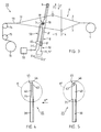
- FIG. 9 shows the device 50 shown in view and partly in section and designed to hold the inserted weft end, which essentially comprises the supporting part 65, an inlet air line 55 arranged thereon and formed from a tubular body, and a holding and guide member 60 arranged thereon.
- the individual elements of the device 50 are described below, the holding and guide member 60 being referred to as a guide member 60 for simplicity.
- the cuboid-shaped support part 65 shown partially in section, is penetrated by a bore 66, which opens into an internal thread 67 at one end.
- the other end of the bore 66 is designed in a manner not shown for the connection of the line 71 'connected to the compressed air source 70 (FIG. 3).
- the supply air line 55 arranged on the support part 65 and penetrated in the axial direction by a bore 56 ' has an orientation approximately orthogonal to the surface 65' of the support part 65 first section 56 and a second section 57 formed thereon and formed in a circular arc with a radius R.
- the radius R of the second section 57 corresponds approximately to three times the diameter of the supply air line 55.
- a screw member 54 and a threaded piece 59 is provided, by means of which the supply air line 55 can be screwed into the internal thread 67 of the support member 65.
- the supply air line 55 is made from a tube with an outside diameter of about 4 mm.
- the guide member 60 On the arcuate second section 57 of the supply air line 55, the guide member 60 is arranged, which has a second air duct 61 oriented in the axial direction.
- the section 57 of the supply air line 55 projects with an end piece 58 into the second air duct 61 of the guide member 60.
- the guide member 60 penetrated in the axial direction by the second air duct 61, has two side surfaces 62 and 62 'arranged parallel to one another and an approximately circular arcuate front surface 63 and an analog rear surface 63 '(Fig.9).
- the outer contour of the guide member 60 and its arrangement on the supply air line 55 is designed such that the guide member 60, as shown schematically in FIG. 3, projects at least partially into the tunnel-shaped first air duct 19 of the reed 8.
- the guide member 60 with the second air channel 61 is arranged corresponding to the first air channel 19 provided in the reed 8 or in the reeds 8 '.
- the distance D shown in FIG. 9 from the surface 65 'of the support member 65 to the imaginary central axis 61' of the guide member 60 is dimensioned such that the weft thread 18 inserted into the first air duct 19 by the high-pressure nozzle 75 (FIG. 1) is exact in the second air channel 61 of the guide member 60 is introduced.
- the distance D of the central axis 61 'of the guide member 60 with respect to the surface 65' of the support member 65 is essentially dependent on the design of the reed 8 'or on the arrangement of the individual recesses 7 forming the first air channel 19 with respect to the non- designated upper edge of the lower cross member 9 'of the sley 10 (Fig.1; 3).
- the supply air line 55 with the guide member 60 arranged and fastened thereon is fastened interchangeably to the support part 65 as a structural unit by the screw connection 54 and 59.
- the end piece 58 of the supply air line 55 is preferably up to in order to achieve an optimal deflection of the compressed air jet P ′ and to detect the weft end 18 ′ introduced into the second air duct 61 on the entry side of the weft end 18 ′ attached to the guide member 60 protruding into the air duct 61.
- the end piece 58 projects at most up to the imaginary central axis 61 ′ into the second air channel 61 of the guide member 60.
- the device 50 is shown in a side view and one can see the supporting part 65, the supply air line 55 and the guide member 60 arranged thereon and partly shown in section with the weft thread end 18 'arranged in the second air duct 61 of the one inserted in the direction of the arrow Y, Y' Weft thread 18.
- the second air duct 61 can be designed to taper conically.
- the arcuate second section 57 of the supply air line 55 is arranged and fastened from the end edge 64 at a distance L 'in a not shown and designated recess of the guide member 60.
- the front section 60 ' serves as an insertion part and the adjoining section 60''acts as a pressurized air Holding part for the weft end 18 '.
- the total length L of the guide member 60 is approximately 30 mm and the distance L 'from the end face 64 to the center of the connection to the guide member 60 is approximately twice the diameter of the tubular supply air line 55.
- sensing elements 68 and 68 ' which are arranged on both sides of the supply air line 55 connected to the guide member 60.
- FIG. 11 shows the device 50 shown in plan view and on a larger scale and one can see the screw member 54 arranged on the surface 65 'with the supply air line 55 and the guide member 60 arranged and fastened thereon.
- the guide member 60 is in relation to the imaginary central axis 61' arranged on the vertical axis 55 'of the supply air line 55 at a distance R'.
- the distance R ' is selected such that the imaginary central axis 61' of the guide member 60 corresponds to the weft thread 18 to be inserted into the shed 12 (FIG. 3) (not shown in FIG. 11).
- the supply air line 55 is connected to the second section 57, shown partly in section, and to the guide member 60, also shown partly in section, in such a way that the one introduced on the support part 65 in the direction of the arrow P (FIG. 9) Compressed air jet is directed into the second air duct 61 of the guide member 60 via the axial bore 56 'and 57' of the two sections 56 and 57 with an optimal flow in the direction of the arrow P '(FIG. 11). Compressed air is additionally applied to the weft thread end 18 '(FIG. 10, 11) introduced in the direction of the arrow Y and held in the extended position in the second air duct 61.
- the second section 57 with its central axis 57 '' is referred to the central axis 61 'of the guide member 60 is connected and fastened to the guide member 60 at an acute angle ⁇ .
- the acute angle ⁇ is approximately in the order of 30 ° to max. 45 °.
- the specified measures mean that the weft thread 18 is carried exactly through the shed, the weft thread end on the outlet side being dimensioned relatively short without the weft thread end jumping back into the shed.
- the direct supply of compressed air and the loading of the weft thread and the weft thread end in the guide element also has the advantage that the compressed air jet emitted by the inlet-side high-pressure nozzle for the entry can be reduced or possibly even switched off when the weft thread end reaches the guide element.
- the compressed air consumption can thereby be reduced by approximately 50% and the energy consumption dependent on it significantly reduced.
- the mode of operation of the device according to the invention is described below:
- the weft thread 18 drawn off in a manner known per se from a supply bobbin, not shown, is passed through the first air duct 19 of the reed 8 into the essentially through the heald frames 4 with the aid of a compressed air jet emitted in the direction of arrow Y (FIG. 1) by the high-pressure nozzle 75 arranged on the entry side and 5 open shed 12 (FIG. 2, 3) are entered and additionally pressurized with compressed air during the entry by the nozzle bodies 25 arranged at a distance from one another in the entry direction and immersed in the shed 12 in this phase.
- the weft thread 18 inserted into the shed 12 by the high pressure nozzle 75 is additionally acted upon by compressed air by means of the nozzle body 25 arranged on the sley 10.
- the nozzle bodies 25 are acted upon individually, one after the other or in groups, one after the other with compressed air in order to act on the weft thread 18.
- the device 50 for holding the weft thread end 18 ′ can additionally be pressurized with compressed air.
- the compressed air supply to the high-pressure nozzle 75 on the entry side and to the individual nozzle bodies 25 is reduced, for example, so that the weft thread end 18 'introduced into the guide member 60 is acted upon by an increased compressed air jet P'.
- the control of the compressed air supply to the high-pressure nozzle 75 and to the individual nozzle bodies 25 and to the device 50 for the weft thread end 18 'to be held in the stretched position takes place, for example, as a function of a signal which is arranged on the outlet side and is not shown, for example an electro / optical sensing element Scanning member is released as soon as the weft end 18 'emerges from the guide member 60 passes the scanning member.
Landscapes
- Engineering & Computer Science (AREA)
- Textile Engineering (AREA)
- Looms (AREA)
Applications Claiming Priority (4)
| Application Number | Priority Date | Filing Date | Title |
|---|---|---|---|
| CH299394A CH688284A5 (de) | 1994-10-04 | 1994-10-04 | Vorrichtung zum Eintragen des Schussfadens in ein Webfach. |
| CH2993/94 | 1994-10-04 | ||
| CH1717/95 | 1995-06-12 | ||
| CH171795 | 1995-06-12 |
Publications (2)
| Publication Number | Publication Date |
|---|---|
| EP0707101A2 true EP0707101A2 (fr) | 1996-04-17 |
| EP0707101A3 EP0707101A3 (fr) | 1997-10-08 |
Family
ID=25688473
Family Applications (1)
| Application Number | Title | Priority Date | Filing Date |
|---|---|---|---|
| EP95115223A Withdrawn EP0707101A3 (fr) | 1994-10-04 | 1995-09-27 | Dispositif d'insertion de la trame dans la foule d'un métier à jet d'air |
Country Status (1)
| Country | Link |
|---|---|
| EP (1) | EP0707101A3 (fr) |
Cited By (3)
| Publication number | Priority date | Publication date | Assignee | Title |
|---|---|---|---|---|
| BE1017893A5 (nl) * | 2007-12-10 | 2009-10-06 | Te Strake Textile Bv | Strekinrichting voor het strekken van een inslagdraad. |
| JP2013136846A (ja) * | 2011-12-28 | 2013-07-11 | Toyota Industries Corp | エアジェット織機のサブノズル |
| EP3739094A1 (fr) * | 2019-05-13 | 2020-11-18 | Tsudakoma Kogyo Kabushiki Kaisha | Buse auxiliaire pour métier à tisser à jet d'air |
Families Citing this family (1)
| Publication number | Priority date | Publication date | Assignee | Title |
|---|---|---|---|---|
| BE1021879B1 (nl) * | 2014-05-22 | 2016-01-25 | Picanol | Strekinrichting voor een inslagdraad |
Family Cites Families (6)
| Publication number | Priority date | Publication date | Assignee | Title |
|---|---|---|---|---|
| CH610222A5 (en) * | 1976-09-07 | 1979-04-12 | Rueti Ag Maschf | Process for producing a nozzle and use of the nozzle |
| DE3204363A1 (de) * | 1982-02-09 | 1983-08-11 | Guenne Webmaschf Gmbh | Verfahren und strahlduese zum transportieren eines schussfadens durch ein webfach mittels druckluft |
| BE1000989A3 (nl) * | 1987-10-09 | 1989-05-30 | Picanol Nv | Inrichting voor het strekken van een inslagdraad bij weefmachines. |
| JPH0665777B2 (ja) * | 1987-11-11 | 1994-08-24 | 日本タングステン株式会社 | 空気噴射式織機用補助ノズルの製造方法 |
| DE3739767A1 (de) * | 1987-11-24 | 1989-06-15 | Dornier Gmbh Lindauer | Stuetzduese fuer webmaschinen mit pneumatischem schusseintrag |
| EP0344104B1 (fr) * | 1988-05-26 | 1993-07-28 | GebràDer Sulzer Aktiengesellschaft | Métier à tisser avec système de réglage de l'insertion de la trame |
-
1995
- 1995-09-27 EP EP95115223A patent/EP0707101A3/fr not_active Withdrawn
Non-Patent Citations (1)
| Title |
|---|
| None |
Cited By (3)
| Publication number | Priority date | Publication date | Assignee | Title |
|---|---|---|---|---|
| BE1017893A5 (nl) * | 2007-12-10 | 2009-10-06 | Te Strake Textile Bv | Strekinrichting voor het strekken van een inslagdraad. |
| JP2013136846A (ja) * | 2011-12-28 | 2013-07-11 | Toyota Industries Corp | エアジェット織機のサブノズル |
| EP3739094A1 (fr) * | 2019-05-13 | 2020-11-18 | Tsudakoma Kogyo Kabushiki Kaisha | Buse auxiliaire pour métier à tisser à jet d'air |
Also Published As
| Publication number | Publication date |
|---|---|
| EP0707101A3 (fr) | 1997-10-08 |
Similar Documents
| Publication | Publication Date | Title |
|---|---|---|
| DE2741859C2 (de) | Pneumatische Webmaschine sowie Schußeintragsvorrichtung dafür | |
| DE2700119C2 (de) | Düsenwebmaschine | |
| DE3740666C1 (de) | Schusseintragvorrichtung fuer pneumatische Webmaschinen mit wenigstens zwei zu einem Buendel zusammengefassten Blasduesen | |
| DE3781707T2 (de) | Verfahren und vorrichtung zum klemmen, festhalten und vorfuehren von schussfaeden bei greiferwebmaschinen. | |
| EP0511939B1 (fr) | Dispositif pneumatique d'insertion des fils de trame et machine à tisser avec ce dispositif | |
| DE2522335C3 (de) | Strahldüse zum Transportieren eines Schußfadens durch ein Webfach mittels eines strömenden Transportmittels | |
| DE3200638A1 (de) | Schuetzenlose webmaschine | |
| EP1169503B1 (fr) | Buse auxiliaire pour metier a tisser mecanique | |
| DE3819426A1 (de) | Pneumatische kettfadeneinzugsvorrichtung am riet einer webmaschine oder dgl. | |
| EP0149969B1 (fr) | Métier à tisser | |
| EP0707101A2 (fr) | Dispositif d'insertion de la trame dans la foule d'un métier à jet d'air | |
| DE3018523A1 (de) | Eintragvorrichtung fuer den schussfaden von einer duesenwebmaschine | |
| CH653060A5 (de) | Schusseintragskanal an einer duesenwebmaschine. | |
| DE3421638C2 (de) | Webblatt mit integriertem Eintragkanal für eine schützenlose Webmaschine mit pneumatischem Schußfadeneintrag | |
| DE3010249C2 (de) | Düsenwebmaschine | |
| DE69703711T2 (de) | Bringergreifer für eine Greiferwebmaschine | |
| DE3220064C2 (fr) | ||
| DE3205644C2 (fr) | ||
| DE29721042U1 (de) | Webmaschine, insbesondere Luftdüsenwebmaschine | |
| DE3034120C2 (de) | Eintragskanal für eine Düsenwebmaschine | |
| CH688284A5 (de) | Vorrichtung zum Eintragen des Schussfadens in ein Webfach. | |
| EP1509645A1 (fr) | Procede permettant de maintenir un fil de trame tendu et machine a tisser permettant d'executer ce procede | |
| EP0053216A1 (fr) | Buse de soufflage auxiliaire pour métier à tisser à jet d'air | |
| EP1365053B1 (fr) | Dispositif de réception et de retention pour l'extrémité du fil de trame dans un métier à tisser | |
| EP1512782A2 (fr) | Métier à tisser avec un dispositif de rentrage de fils de trame |
Legal Events
| Date | Code | Title | Description |
|---|---|---|---|
| PUAI | Public reference made under article 153(3) epc to a published international application that has entered the european phase |
Free format text: ORIGINAL CODE: 0009012 |
|
| AK | Designated contracting states |
Kind code of ref document: A2 Designated state(s): AT BE CH DE FR GB IT LI |
|
| PUAL | Search report despatched |
Free format text: ORIGINAL CODE: 0009013 |
|
| AK | Designated contracting states |
Kind code of ref document: A3 Designated state(s): AT BE CH DE FR GB IT LI |
|
| 17P | Request for examination filed |
Effective date: 19980411 |
|
| STAA | Information on the status of an ep patent application or granted ep patent |
Free format text: STATUS: THE APPLICATION HAS BEEN WITHDRAWN |
|
| 18W | Application withdrawn |
Withdrawal date: 19991027 |