EP0707165A2 - Automatisches Mehrganggetriebe mit Drehmomentwandler - Google Patents
Automatisches Mehrganggetriebe mit Drehmomentwandler Download PDFInfo
- Publication number
- EP0707165A2 EP0707165A2 EP95307138A EP95307138A EP0707165A2 EP 0707165 A2 EP0707165 A2 EP 0707165A2 EP 95307138 A EP95307138 A EP 95307138A EP 95307138 A EP95307138 A EP 95307138A EP 0707165 A2 EP0707165 A2 EP 0707165A2
- Authority
- EP
- European Patent Office
- Prior art keywords
- converter
- clutch
- pressure
- torque
- control
- Prior art date
- Legal status (The legal status is an assumption and is not a legal conclusion. Google has not performed a legal analysis and makes no representation as to the accuracy of the status listed.)
- Granted
Links
- 230000005540 biological transmission Effects 0.000 title claims description 29
- 238000005461 lubrication Methods 0.000 claims description 19
- 230000000694 effects Effects 0.000 claims description 8
- 239000012530 fluid Substances 0.000 claims description 4
- 230000001970 hydrokinetic effect Effects 0.000 claims description 4
- 230000007423 decrease Effects 0.000 claims description 3
- 230000009467 reduction Effects 0.000 claims description 2
- 230000001105 regulatory effect Effects 0.000 claims description 2
- 239000003921 oil Substances 0.000 claims 8
- 230000001419 dependent effect Effects 0.000 claims 1
- 239000010687 lubricating oil Substances 0.000 claims 1
- 238000011217 control strategy Methods 0.000 description 31
- 238000010586 diagram Methods 0.000 description 15
- 238000006243 chemical reaction Methods 0.000 description 8
- 230000008878 coupling Effects 0.000 description 6
- 238000010168 coupling process Methods 0.000 description 6
- 238000005859 coupling reaction Methods 0.000 description 6
- 230000000670 limiting effect Effects 0.000 description 6
- 230000001360 synchronised effect Effects 0.000 description 6
- 238000001816 cooling Methods 0.000 description 5
- 101150100654 pacC gene Proteins 0.000 description 5
- 230000007704 transition Effects 0.000 description 5
- 230000001276 controlling effect Effects 0.000 description 4
- 230000002441 reversible effect Effects 0.000 description 4
- 230000001960 triggered effect Effects 0.000 description 4
- 230000008901 benefit Effects 0.000 description 3
- 238000012795 verification Methods 0.000 description 3
- 101100203596 Caenorhabditis elegans sol-1 gene Proteins 0.000 description 2
- 230000001133 acceleration Effects 0.000 description 2
- 239000008186 active pharmaceutical agent Substances 0.000 description 2
- 238000004364 calculation method Methods 0.000 description 2
- 230000008859 change Effects 0.000 description 2
- 238000005336 cracking Methods 0.000 description 2
- 238000013461 design Methods 0.000 description 2
- 239000000446 fuel Substances 0.000 description 2
- 230000020169 heat generation Effects 0.000 description 2
- 238000000034 method Methods 0.000 description 2
- 238000012544 monitoring process Methods 0.000 description 2
- 230000008569 process Effects 0.000 description 2
- 230000002829 reductive effect Effects 0.000 description 2
- 101001059713 Homo sapiens Inner nuclear membrane protein Man1 Proteins 0.000 description 1
- 102100028799 Inner nuclear membrane protein Man1 Human genes 0.000 description 1
- 238000004873 anchoring Methods 0.000 description 1
- 238000013459 approach Methods 0.000 description 1
- 238000002485 combustion reaction Methods 0.000 description 1
- 238000005094 computer simulation Methods 0.000 description 1
- 238000013016 damping Methods 0.000 description 1
- 230000003247 decreasing effect Effects 0.000 description 1
- 230000017525 heat dissipation Effects 0.000 description 1
- 230000006872 improvement Effects 0.000 description 1
- 238000012886 linear function Methods 0.000 description 1
- 238000004519 manufacturing process Methods 0.000 description 1
- 230000007935 neutral effect Effects 0.000 description 1
- 238000013021 overheating Methods 0.000 description 1
- 230000036961 partial effect Effects 0.000 description 1
- 230000007363 regulatory process Effects 0.000 description 1
- 239000013589 supplement Substances 0.000 description 1
Images






Classifications
-
- F—MECHANICAL ENGINEERING; LIGHTING; HEATING; WEAPONS; BLASTING
- F16—ENGINEERING ELEMENTS AND UNITS; GENERAL MEASURES FOR PRODUCING AND MAINTAINING EFFECTIVE FUNCTIONING OF MACHINES OR INSTALLATIONS; THERMAL INSULATION IN GENERAL
- F16H—GEARING
- F16H61/00—Control functions within control units of change-speed- or reversing-gearings for conveying rotary motion ; Control of exclusively fluid gearing, friction gearing, gearings with endless flexible members or other particular types of gearing
- F16H61/14—Control of torque converter lock-up clutches
- F16H61/143—Control of torque converter lock-up clutches using electric control means
-
- F—MECHANICAL ENGINEERING; LIGHTING; HEATING; WEAPONS; BLASTING
- F16—ENGINEERING ELEMENTS AND UNITS; GENERAL MEASURES FOR PRODUCING AND MAINTAINING EFFECTIVE FUNCTIONING OF MACHINES OR INSTALLATIONS; THERMAL INSULATION IN GENERAL
- F16H—GEARING
- F16H61/00—Control functions within control units of change-speed- or reversing-gearings for conveying rotary motion ; Control of exclusively fluid gearing, friction gearing, gearings with endless flexible members or other particular types of gearing
- F16H61/02—Control functions within control units of change-speed- or reversing-gearings for conveying rotary motion ; Control of exclusively fluid gearing, friction gearing, gearings with endless flexible members or other particular types of gearing characterised by the signals used
- F16H61/0202—Control functions within control units of change-speed- or reversing-gearings for conveying rotary motion ; Control of exclusively fluid gearing, friction gearing, gearings with endless flexible members or other particular types of gearing characterised by the signals used the signals being electric
- F16H61/0204—Control functions within control units of change-speed- or reversing-gearings for conveying rotary motion ; Control of exclusively fluid gearing, friction gearing, gearings with endless flexible members or other particular types of gearing characterised by the signals used the signals being electric for gearshift control, e.g. control functions for performing shifting or generation of shift signal
- F16H61/0206—Layout of electro-hydraulic control circuits, e.g. arrangement of valves
-
- F—MECHANICAL ENGINEERING; LIGHTING; HEATING; WEAPONS; BLASTING
- F16—ENGINEERING ELEMENTS AND UNITS; GENERAL MEASURES FOR PRODUCING AND MAINTAINING EFFECTIVE FUNCTIONING OF MACHINES OR INSTALLATIONS; THERMAL INSULATION IN GENERAL
- F16H—GEARING
- F16H59/00—Control inputs to control units of change-speed- or reversing-gearings for conveying rotary motion
- F16H59/02—Selector apparatus
- F16H59/08—Range selector apparatus
- F16H2059/082—Range selector apparatus for different transmission modes
-
- F—MECHANICAL ENGINEERING; LIGHTING; HEATING; WEAPONS; BLASTING
- F16—ENGINEERING ELEMENTS AND UNITS; GENERAL MEASURES FOR PRODUCING AND MAINTAINING EFFECTIVE FUNCTIONING OF MACHINES OR INSTALLATIONS; THERMAL INSULATION IN GENERAL
- F16H—GEARING
- F16H59/00—Control inputs to control units of change-speed- or reversing-gearings for conveying rotary motion
- F16H59/36—Inputs being a function of speed
- F16H59/38—Inputs being a function of speed of gearing elements
- F16H2059/385—Turbine speed
-
- F—MECHANICAL ENGINEERING; LIGHTING; HEATING; WEAPONS; BLASTING
- F16—ENGINEERING ELEMENTS AND UNITS; GENERAL MEASURES FOR PRODUCING AND MAINTAINING EFFECTIVE FUNCTIONING OF MACHINES OR INSTALLATIONS; THERMAL INSULATION IN GENERAL
- F16H—GEARING
- F16H59/00—Control inputs to control units of change-speed- or reversing-gearings for conveying rotary motion
- F16H59/36—Inputs being a function of speed
- F16H59/46—Inputs being a function of speed dependent on a comparison between speeds
- F16H2059/465—Detecting slip, e.g. clutch slip ratio
- F16H2059/467—Detecting slip, e.g. clutch slip ratio of torque converter
-
- F—MECHANICAL ENGINEERING; LIGHTING; HEATING; WEAPONS; BLASTING
- F16—ENGINEERING ELEMENTS AND UNITS; GENERAL MEASURES FOR PRODUCING AND MAINTAINING EFFECTIVE FUNCTIONING OF MACHINES OR INSTALLATIONS; THERMAL INSULATION IN GENERAL
- F16H—GEARING
- F16H61/00—Control functions within control units of change-speed- or reversing-gearings for conveying rotary motion ; Control of exclusively fluid gearing, friction gearing, gearings with endless flexible members or other particular types of gearing
- F16H61/0021—Generation or control of line pressure
- F16H2061/0037—Generation or control of line pressure characterised by controlled fluid supply to lubrication circuits of the gearing
-
- F—MECHANICAL ENGINEERING; LIGHTING; HEATING; WEAPONS; BLASTING
- F16—ENGINEERING ELEMENTS AND UNITS; GENERAL MEASURES FOR PRODUCING AND MAINTAINING EFFECTIVE FUNCTIONING OF MACHINES OR INSTALLATIONS; THERMAL INSULATION IN GENERAL
- F16H—GEARING
- F16H61/00—Control functions within control units of change-speed- or reversing-gearings for conveying rotary motion ; Control of exclusively fluid gearing, friction gearing, gearings with endless flexible members or other particular types of gearing
- F16H61/14—Control of torque converter lock-up clutches
- F16H61/143—Control of torque converter lock-up clutches using electric control means
- F16H2061/145—Control of torque converter lock-up clutches using electric control means for controlling slip, e.g. approaching target slip value
-
- F—MECHANICAL ENGINEERING; LIGHTING; HEATING; WEAPONS; BLASTING
- F16—ENGINEERING ELEMENTS AND UNITS; GENERAL MEASURES FOR PRODUCING AND MAINTAINING EFFECTIVE FUNCTIONING OF MACHINES OR INSTALLATIONS; THERMAL INSULATION IN GENERAL
- F16H—GEARING
- F16H61/00—Control functions within control units of change-speed- or reversing-gearings for conveying rotary motion ; Control of exclusively fluid gearing, friction gearing, gearings with endless flexible members or other particular types of gearing
- F16H61/14—Control of torque converter lock-up clutches
- F16H61/143—Control of torque converter lock-up clutches using electric control means
- F16H2061/146—Control of torque converter lock-up clutches using electric control means for smoothing gear shift shock
-
- F—MECHANICAL ENGINEERING; LIGHTING; HEATING; WEAPONS; BLASTING
- F16—ENGINEERING ELEMENTS AND UNITS; GENERAL MEASURES FOR PRODUCING AND MAINTAINING EFFECTIVE FUNCTIONING OF MACHINES OR INSTALLATIONS; THERMAL INSULATION IN GENERAL
- F16H—GEARING
- F16H2312/00—Driving activities
- F16H2312/02—Driving off
-
- F—MECHANICAL ENGINEERING; LIGHTING; HEATING; WEAPONS; BLASTING
- F16—ENGINEERING ELEMENTS AND UNITS; GENERAL MEASURES FOR PRODUCING AND MAINTAINING EFFECTIVE FUNCTIONING OF MACHINES OR INSTALLATIONS; THERMAL INSULATION IN GENERAL
- F16H—GEARING
- F16H59/00—Control inputs to control units of change-speed- or reversing-gearings for conveying rotary motion
- F16H59/36—Inputs being a function of speed
-
- F—MECHANICAL ENGINEERING; LIGHTING; HEATING; WEAPONS; BLASTING
- F16—ENGINEERING ELEMENTS AND UNITS; GENERAL MEASURES FOR PRODUCING AND MAINTAINING EFFECTIVE FUNCTIONING OF MACHINES OR INSTALLATIONS; THERMAL INSULATION IN GENERAL
- F16H—GEARING
- F16H59/00—Control inputs to control units of change-speed- or reversing-gearings for conveying rotary motion
- F16H59/36—Inputs being a function of speed
- F16H59/44—Inputs being a function of speed dependent on machine speed, e.g. the vehicle speed
-
- F—MECHANICAL ENGINEERING; LIGHTING; HEATING; WEAPONS; BLASTING
- F16—ENGINEERING ELEMENTS AND UNITS; GENERAL MEASURES FOR PRODUCING AND MAINTAINING EFFECTIVE FUNCTIONING OF MACHINES OR INSTALLATIONS; THERMAL INSULATION IN GENERAL
- F16H—GEARING
- F16H59/00—Control inputs to control units of change-speed- or reversing-gearings for conveying rotary motion
- F16H59/68—Inputs being a function of gearing status
- F16H59/72—Inputs being a function of gearing status dependent on oil characteristics, e.g. temperature, viscosity
-
- F—MECHANICAL ENGINEERING; LIGHTING; HEATING; WEAPONS; BLASTING
- F16—ENGINEERING ELEMENTS AND UNITS; GENERAL MEASURES FOR PRODUCING AND MAINTAINING EFFECTIVE FUNCTIONING OF MACHINES OR INSTALLATIONS; THERMAL INSULATION IN GENERAL
- F16H—GEARING
- F16H61/00—Control functions within control units of change-speed- or reversing-gearings for conveying rotary motion ; Control of exclusively fluid gearing, friction gearing, gearings with endless flexible members or other particular types of gearing
- F16H61/0021—Generation or control of line pressure
Definitions
- the invention relates to multiple ratio torque converter transmissions for automotive vehicles and to electronic-hydraulic controls for effecting engagement and release of a converter clutch.
- Our invention is adapted to be used in a multiple ratio planetary transmission situated in a vehicle driveline having an internal combustion engine with a throttle control and a hydrokinetic torque converter situated between the engine and input elements of the gearing.
- the gearing comprises two simple planetary gear units arranged in a manner similar to the gearing arrangement of the well known Simpson gear set. Located between the turbine of the torque converter and the input elements of the Simpson gearing is a third simple planetary gear unit with a friction clutch adapted to connect two elements of the third gear unit together for rotation in unison. A friction brake also is used for anchoring a reaction element of the third planetary gear unit. An overrunning coupling establishes one-way torque flow between two elements of the gearing. The brake is arranged in series relationship with respect to the clutch.
- a second overrunning coupling in a gear unit of the Simpson gearing is used for the purpose of establishing a non-synchronous ratio shift.
- Forward engagement is achieved by engaging a forward clutch on a shift from neutral to the drive state.
- a separate reverse engagement clutch is used to establish a torque flow path for reverse.
- turbine speed is used as a feedback signal to initiate the start of the forward or reverse engagement.
- Ratio changes between the first ratio and the second ratio on an upshift, as well as a downshift from the second ratio to the first ratio, is achieved in our improved transmission by controlling the engagement of an overrunning clutch.
- the overrunning clutch is arranged in series relationship with respect to a friction brake as a reaction torque flow path for the friction brake associated with the intermediate ratio is established and disestablished.
- the braking of the friction brake is accomplished with a closed loop control so that harshness is avoided as the overrunning elements of the reaction torque flow path engage. This is in contrast to prior art arrangements, such as that shown in U.S. Patent No. 5,157,608, where a non-synchronous shift using overrunning couplings is achieved without the cushioning effect made available by the present invention as the associated friction brake is actuated.
- Our transmission includes a torque converter controller for a torque converter clutch that has a single converter feed passage and a single converter flow return passage.
- Such converters are distinguishable from converters of the kind shown, for example, in U.S. Patent No. 5,305,663 where a converter bypass clutch feed passage acts in cooperation with two other distinguishable feed passages, one acting as a flow return and the other acting as a flow delivery to the torque circuit of the converter.
- a converter bypass clutch feed passage acts in cooperation with two other distinguishable feed passages, one acting as a flow return and the other acting as a flow delivery to the torque circuit of the converter.
- continuous flow is achieved through the converter regardless of whether the clutch is engaged or released.
- the converter is a three pass system that accommodates continuous flow through the converter regardless of the behavior of the clutch. Notwithstanding the fact that the converter has only two flow paths, one toward the converter and the other from the converter, the converter oil flow is capable of maintaining sufficient heat dissipation because of an improved converter flow arrangement in the converter circuit.
- a converter clutch modulator valve that provides the converter flow. The converter flow is divided into two components, one part of which is directed to a thermostat bypass valve into a lubrication system as the other flow component enters the transmission cooler.
- the controller for the converter uses features that are common to the electronically controlled bypass clutch strategy of U.S. Patent No. 5,303,616 where the percentage of shift completion is used as an input parameter for controlling the engagement of a bypass clutch for a converter, particularly, during ratio changes.
- the converter control valve system with which the control strategy is used is capable of accurately adjusting the pressure differential across a converter clutch piston in the converter torus cavity. This involves the use of a single converter pressure modulator solenoid valve, which directly controls the torus cavity pressure. In contrast, two pressure modulators are required in prior art designs in which the release side of the converter clutch piston is controlled as well as the torus cavity pressure. This feature simplifies the converter control valve system of the present invention.
- the valve system of the present invention also uses a simplified accumulator valve to create a controlled back pressure on the release side of the converter clutch piston thereby simplifying the control of pressure differential across the converter clutch piston as converter clutch torque capacity is regulated.
- the converter clutch control makes it feasible to operate the converter clutch in each ratio using closed loop feedback control. Inertia torque changes during shifts are moderated in this way, thereby reducing shift harshness. The ability to apply the converter clutch in all gear ratios contributes to improved fuel economy.
- Improved performance also is achieved by reducing hydrokinetic power loss during acceleration and deceleration.
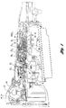
- the transmission gearing contains an overdrive planetary gear set connected in series with a Simpson set.
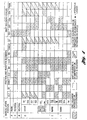
- Figure 1 shows the various clutches and bands with conventional abbreviations.
- Figure 2 shows, in schematic form, the torque flow paths for the transmission.
- the engine torque is transmitted to the housing of the torque converter pump or impeller 22.
- the converter impeller is a centrifugal pump which accelerates the fluid inside the torque converter towards the blades of turbine 24.
- the accelerated oil is then decelerated over the turbine blades and the oil at the turbine exit is redirected over the converter reacter back into the impeller, thereby achieving a torque multiplication effect.
- the torque is transmitted to overrunning coupling OWC1, which effects a torque reaction in the rotational direction of the engine.
- the coupling OWC1 overruns in the opposite direction.
- the engaged clutch CL3 carries torque from the center shaft to the first of two simple planetary gear units of a Simpson gear set.
- the torque is delivered to the ring gear 30 and then is split into two components. One part is delivered over the planetary carrier 32 to the output shaft 34, which turns in the same rotational direction as the ring gear 30.
- the sun gear 36 carries the remaining part of the torque in the opposite direction to the rear gear set of the Simpson planetary gear set.
- the planetary carrier 38 of the rear planetary gear set is held by overrunning coupling OWC2.
- the torque delivered to the sun gear 42 is then transmitted over the planetaries to the ring gear 40, which reduces the velocity and multiplies the torque to the output shaft. This arrangement provides a 2.474 gear ratio.
- the torque flow is the same as in 1st gear except that B2 is applied. With the engagement of B2, the sun gear speed is reduced to zero speed.
- the brake band (B2) serves as a reaction element for the front planetary gear set and generates an output torque multiplication of 1.474 by holding 0.474 times engine torque as a reaction to the output.
- the output of the rear planetary gearset is zero since the sun gear 42 has zero speed (see Figure 2).
- the converter clutch 44 can be locked or unlocked in 2nd gear depending on the driving condition.
- the coast clutch (CL1) is disengaged - i.e., electronically released - and free wheeling takes place since OWC1 overruns in coast mode (see Figure 2).
- This is the direct gear with a gear ratio of one. Since the gear change from 2nd to 3rd and from 3rd to 2nd has to be synchronized, more complex control functions are implemented for these gear changes.
- B1 In 4th gear, B1 is applied and carries -.25 times engine torque as a reaction to the output. B1 decelerates the sun gear of the overdrive planetary gear set to zero speed and generates a gear ratio of .75. Engagement of CL1 is hydraulically inhibited and OWC1 overruns. Since B1 carries 0.25 times engine torque and since the overdrive planetary gear set is an input to the Simpson set, CL2 and CL3 are holding the 0.75th fraction of engine torque. The gear ratio is 0.75.
- the converter clutch can be locked or unlocked based on the driving condition (see Figure 2.)
- the torque flow is the same as in 1st gear in drive position except B3 and CL1 are applied to generate engine braking in coast mode.
- the converter clutch is hydraulically inhibited and cannot be applied electronically.
- B3 prevents overrunning of OWC2
- CL1 prevents overrunning of OWC1.
- the gear ratio is 2.474 (see Figure 2).
- the torque flow is the same as in 2nd gear in drive position except CL1 is applied to achieve engine braking in coast mode. CL1 prevents overrunning of OWC1 in power OFF condition.
- the converter clutch control system has a dedicated hydraulic control system as well as a unique control strategy.
- the converter clutch is electronically controlled and can be engaged in each gear. Usually, the converter clutch will be locked starting in second gear, and it stays locked. By monitoring engine speed 'N' and the turbine speed "NT", the state of the converter clutch or the amount of slip is determined.
- NT turbine speed
- the state of the converter clutch or the amount of slip is determined.
- the control system is able to adjust for the desired amount of differential speed during an upshift event or a downshift event. This requires a control system which is capable of adjusting capacity on the converter clutch.
- Converter clutch control systems for some known transmissions are partially electronically controlled (ON/OFF-solenoid) and are only capable of controlling the converter clutch in either “ON” or “OFF” states. This restricts the converter clutch operation only to operation in fourth or third gear.
- the converter clutch control system of the present invention can also be operated as a simple ON/OFF system since the clutch capacity can be varied from 0% to 100%. It can also be operated, however, as a "full" modulated clutch with continuous slip under all operating conditions.
- the converter clutch can be controlled with two different hardware configurations:
- the converter clutch control strategy is described for each item. A brief description of the strategy has been set forth previously. In addition, the cooling system with the new thermostat bypass valve system will be described.
- Control Strategy The following are the control parameters for the complete control system, including the control strategy: Control Strategy:
- the torque converter is a two-pass, reverse-flow torque converter. In unlock mode, 0% duty cycle is applied to the PWM solenoid. Zero percent duty cycle produces zero output pressure from the PWM solenoid.
- the converter clutch modulator valve 98 in bore 200 is in the downshift position. The converter charge pressure is produced by the main regulator 104 system in bore 208.
- line pressure is in equilibrium with EPC output pressure produced by variable force solenoid 18 in bore 203.
- the surplus oil generated by the line pressure regulating process is directed into the pump BYPASS circuit 105 and into the converter charge (CC) passage 150.
- the surplus oil in the converter charge circuit builds up the converter charge (CC) pressure.
- the converter charge pressure is distributed through orifices 298 and 300 as an input pressure to the converter clutch modulator valve 98 in bore 200.
- the converter limit valve 94 (blow-off valve) limits the CC pressure to a maximum level of 8 bar.
- the converter charge pressure is directed over the downshifted converter clutch modulator valve 98 into the CC/BP circuit and finally to the torque converter.
- the charge oil enters the torque converter at the back side of the converter clutch plate into the torus. It serves as the transmitting medium for the torque converter function.
- the remaining converter oil enters the converter discharge circuit 103 (CDC) and is redirected to an input port of the converter clutch modulator valve 98 in bore 200.
- the discharge oil From the converter clutch modulator valve, the discharge oil enters the cooler circuit 154 and is split into two flow components. One part is directed over the thermostat bypass valve directly into the lubrication circuit 155. The other oil flow component enters the cooler first and then the lubrication system.
- the cooling and lubrication system is described subsequently in detail.
- a metered amount of cooler flow is bypassed through the control orifice 302 and orifices 168 and 304 into the CC/ACC circuit.
- This bypassed oil serves as a feed to the converter clutch accumulator system in bore 216. The purpose of this accumulator system is explained subsequently.
- the duty cycle of the PWM solenoid is raised to a value between 10% and 20% depending on the input pressure (see Figure 7) in order to produce enough output pressure to overcome the spring load in bore 200.
- the converter clutch modulator valve moves into upshift position.
- Solenoid 1 pressure is the input pressure to the PWM solenoid 20.
- Solenoid 1 pressure is produced by the solenoid 1 regulator 158 in bore 201.
- the regulator valve 158 limits line pressure to 8 bar.
- the pressure limitation is required in order not to exceed the cracking pressure of the PWM solenoid.
- the cracking pressure is currently set at 10 bar.
- the front land of the valve opens the pressure output port of the PWM solenoid to the CDC/MOD circuit, which is connected to the converter clutch apply side.
- the converter clutch is directly controlled by the PWM solenoid. This requires a "HIGH FLOW" PWM solenoid design in order to satisfy the stroke volume of the clutch itself and to cover the cooling flow to the clutch.
- the last land opens the accumulator circuit 301 (CC/ACC) to the CC/BP circuit 303, which is connected to the back side of the converter clutch plate.
- a converter clutch accumulator valve 86 is installed in bore 216.
- the accumulator is fed with cooler oil supplied by the control orifice 302.
- the output pressure of the PWM-solenoid 20 is directly applied to the front side of the converter clutch.
- the pressure characteristic applied to the converter bypass clutch is determined by the input pressure to the PWM-solenoid and the pressure characteristic.
- the graph of Figure 7 shows a diagram PWM pressure versus percent duty cycle.
- the two linear pressure lines represent the pressure characteristics with 4 bar and 8 bar input pressure.
- the lower end is limited by the accumulator threshold PACC.
- the shadowed area represents the pressure control range applied to the converter clutch.
- the accumulator pressure is applied on the back side of the converter clutch and reduces the clutch capacity applied at the front of the clutch plate.
- any ⁇ -pressure between the PWM solenoid pressure characteristic and the accumulator threshold can be adjusted.
- This accumulator system will equalize the applied capacity on the converter clutch when the converter clutch modulator valve 98 is upshifted.
- the capability of adjusting any ⁇ -pressures on the converter clutch produces the ability of adjusting any ⁇ -speed targets for variable torque inputs.
- a capacity determined by the PVALVE threshold would be applied every time when the converter clutch control strategy commands a transition from unlock to lock up mode. Further, the adjustment of a slip target value by the control strategy could only be accomplished with a certain amount of input torque since the PVALVE pressure threshold would already account for this amount of input torque.
- variable capacity control system With this pressure characteristic applied to the converter clutch, a variable capacity control system has been introduced. With feedback control applied to this system the converter clutch can be controlled under all desired operating modes; i.e., unlock mode, slip mode or "full" lock up mode with 100% capacity.
- the converter clutch control valve is hydraulically interlocked with 1/R pressure, which means that converter clutch control operation is inhibited in REVERSE and MAN1 position.
- the upshifted converter clutch modulator valve 98 in bore 200 redirects the converter charge pressure in lock up mode into the cooler circuit 154.
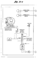
- the cooler pressure is the split up into two flow components which are the cooler flow passage 107 and the bypass lubrication flow passage 109 (see Figure 5b-a and 5b-b).
- the converter clutch module is dedicated to the control of the converter bypass clutch.
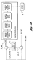
- the major output register is the bypass clutch duty cycle called BCSDC. This duty cycle is applied to the PWM-solenoid 20, which converts the duty cycle signal into an output pressure (see Figures 5e and 5f).
- BCSDC bypass clutch duty cycle
- the converter clutch module is sub-divided in the following major sub-modules:
- This module contains a shift pattern TP vs. VS to lock or unlock the converter bypass clutch in each gear. Based on these shift curves, the converter clutch can be locked in 2nd, 3rd and 4th gear.
- the converter clutch shift schedule can be modified when the transmission oil temperature (TOT) has exceeded a certain value.
- TOT transmission oil temperature
- An open torque converter can contribute to excessive heat generation under heavy driving condition. In order to prevent overheating of the torque converter and the transmission, the converter can be locked at earlier vehicle speeds.
- This module determines the "TARGET" bypass clutch slip values depending on the driving condition. It loads the target slip values into a register called SLIP_TRG_S. The target slip value is then used to PID (proportional, integral, derivative) control the actual slip (SLIP_ACT) to the target value.
- PID proportional, integral, derivative
- the "torque feed forward" system of the present invention contains an "inverse state model" of the converter clutch.
- the input to this model is the input torque TQ_BAR and SLIP_TCAP, which is the total desired slip across the torque converter.
- the output from this inverse model is the bypass clutch duty cycle BCSDC, as shown at 66.
- the inverse model basically includes an inverse torque converter model, an inverse bypass clutch model, an inverse control valve model and an inverse PWM-solenoid model.
- SLIP_TCAP is the sum of the desired slip SLIP_DES and the PID-controlled slip SLIP_ERR_PID.
- ERR_TO is the difference between SLIP_ACT and SLIP_DES.
- This slip error is used to calculate, with the PID-controller gains, the amount of PID-controlled slip. Assuming that the converter hardware correlates with the inverse model, the calculated duty cycle should generate the amount of slip asked by SLIP_TCAP.
- Figure 5d shows the complete system.
- This system has the advantage of controlling a converter clutch system partially open loop and partially closed loop. This can be controlled by increasing or decreasing the amount of PID-controlled slip (SLP_ERR_PID) (see Figure 5c-a and 5c-b). The calculated total slip is then fed along with the input torque through the inverse model.
- SLP_ERR_PID PID-controlled slip
- the "modulation over the shift” controls the desired slip value across the torque converter when a shift is taking place.
- the converter clutch can be modulated during upshifts and downshifts.
- the major tool for adjusting a slip value during a shift is the torque feed forward system described above. The complete system for the application is described subsequently.
- This module is responsible for unlocking the torque converter clutch completely, which means that the BCSDC value is set to zero percent. This produces zero pressure on the converter clutch apply side and unconditionally unlocks it. Unconditional unlock is commanded when extreme driving conditions take place; like braking, tip-in, tip-out, closed throttle condition, etc. The unconditional unlock system for the transmission is shown and described below.
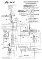
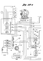
- the hydraulic control system for the converter are included in the system drawings of Figures 5a-a, 5a-b, 5b-a and 5b-b.
- the hydraulic control system for the converter which is packaged in a main control assembly, includes:
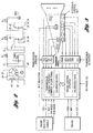
- the system is designed as a closed loop control system.
- Engine speed "NE” and turbine speed “NT” are fed back into the control strategy. From the engine and turbine speed signals, the actual speed values are calculated. From the turbine speed “NT” and the engine speed “NE”, the actual slip SLIP_ACT is calculated. The difference between the actual slip value SLIP_ACT and the desired slip value SLIP_DES is the slip error ERR_TO.
- This slip error is input to a PID-controller 111 which calculates the total PID slip error SLIP_ERR_PID consisting of proportional, integral and derivative terms. The desired slip SLIP_DES is then added to the PID slip error SLIP_ERR_PID resulting in the total slip desired SLIP_TCAP.
- the total requested torque capacity TCAP_REQ is now transformed into a duty cycle by an inverse state model of the complete converter clutch control system.
- This inverse state model consists of three functions.
- the first function is the capacity characteristic of the converter clutch with the TCAP_REQ value as an input, providing a requested DELTA-pressure as an output.
- the converter clutch capacity characteristic is a linear function pressure versus clutch capacity.
- the DELTA-pressure is an input for a control function of the modulator valve 98 and the accumulator valve system 86. Since the converter clutch valve is only an ON/OFF type of shift valve, only the accumulator pressure is here considered. The accumulator pressure is subtracted from the DELTA-pressure resulting in the required PWM-pressure.
- a temperature compensation function for the PWM-solenoid 20 is finally input to a table EPC versus PWM-pressure to convert the PWM-pressure into a duty cycle (Figure 5c-b).
- This table is EPC dependant since the input pressure to the PWM-solenoid, which is solenoid 1 pressure (SOL1), varies with the EPC output pressure of the variable force solenoid.
- the resulting duty cycle has to be compensated with battery voltage. This is done by a function VBAT versus DC.
- the final duty cycle is applied to the PWM-solenoid, which produces the required pressure to accomplish a slip target requested by the calculated SLIP_TCAP value.
- This inverse state model is designed to accomplish a fast capacity adjustment when the input torque changes.
- the inverse torque capacity calculation in combination with the inverse converter state model, enables the control system to react in a closed loop controlled manner very fast to various torque changes in order to adjust the desired slip value. This prevents unnecessary heat generation in the torque converter due to excessive slip values which could be triggered from input torque changes.
- This control strategy is called torque feed forward.
- Figure 8 shows how the converter clutch is controlled during a 2-3 upshift. Partial slip values are adjusted by the above described closed loop converter clutch control system during a 2-3 upshift event.
- the converter clutch function is equivalent to any other upshift or downshift.
- the driver desires a 2-3 upshift, which is triggered by functions of throttle position versus vehicle speed.
- the GR_DS register is changed to 3, and the shift verification timer TM_VER_SFT is loaded.
- a desired slip value SLIP_DES is commanded according to the target slip value SLIP_TARGET, and the duty cycle output register BCSDC reduces the duty cycle value from 100% to an initial value.
- the converter clutch control strategy adjusts during the shift verification time the desired amount of slip during closed loop control, which is imperceptible to the driver.
- the PWM-solenoid reduces the CDC/MOD pressure from the maximum pressure to the pressure which is equivalent to the applied duty cycle.
- the converter clutch loses capacity and the engine rpm starts to rise.
- the shift verification timer TM_VER_SFT is expired and the gear commanded register GR_CM is changed to 3.
- the shift solenoid flags are set or reset according to the shift solenoid states to execute a 2-3 upshift.
- the SLIP_DES value stays at the previous value.
- the converter clutch control strategy calculates the required torque capacity during closed loop control in order to adjust the desired slip value SLIP_DES.
- the inverse state model converts the required torque capacity into a duty cycle input to the PWM-solenoid.
- the shift solenoids are energized or de-energized according to the state of the shift solenoid flags.
- the applied duty cycle to the PWM-solenoid is transformed into a PWM-pressure trying to adjust the desired slip value in a closed loop controlled manner.
- the control strategy monitors the percentage shift complete register.
- the desired slip value SLIP_DES increases. Since the target slip value SLIP_TARGET is smaller than the desired slip value SLIP_DES, the duty cycle percentage increases. This is based on the increasing slip error ERR_TO, which is input to the PID-controller. Hence the PID-controller calculates lower slip values resulting in higher duty cycle settings.
- the high clutch (CL2) transmits torque and the 2-3 upshift is initiated.
- the turbine speed drops and introduces higher slip values triggered by the upshift event.
- the slip desired value SLIP_DES increases and higher percentages of duty cycle are commanded. This increases the PWM-pressure and the converter clutch capacity in order to reduce the amount of slip.
- the percentage shift complete register PCSFTCMPT is greater than a calibratable value. At this point the target slip value SLIP_TARGET is set to zero and the actual slip value is captured. The duty cycle BCSDC increases dramatically in order to reduce the amount of slip.
- the pressure on the converter clutch increases according to the desired duty cycle value.
- the DELTA-pressure profile increases dramatically in order to reduce the slip value to the commanded target slip value SLIP_TARGET.
- the desired slip value SLIP_DES is zero and equal to the target slip value SLIP_TARGET.
- the previously captured slip value is decayed from the capturing point to zero rpm slip. The decaying process has to be synchronized with the 2-3 upshift event.
- the pressure on the converter clutch has increased to a level where zero rpm slip is present.
- the 2-3 upshift is completed, and zero slip on the converter clutch is synchronized with the completion of the shift.
- the hatched area of Figure 8 between engine rpm and turbine speed shows the closed loop operation of the converter clutch.
- the DELTA pressure applied on the converter clutch is also shown as a hatched area.
- control strategy is shown in the flow diagram of Figure 6.
- the hydraulic control system is generally identical to the control system described previously. The only difference is the disconnection of the 1/R pressure by closing orifice 306 ( Figure 11a-a and 11a-b) and the connection of pressure of shift solenoid 4 (SS4), shown at 16, on the back of the converter clutch modulator valve 98 in bore 200 by opening orifice 308. This option provides an additional control feature to override the PWM-function.
- the converter clutch modulator valve 98 With the shift solenoid 4 (SS4) energized, the converter clutch modulator valve 98 is downshifted independently of the PWM-pressure. The control valve moves to downshift position and the converter modulator oil is allowed to enter the release chamber on the backside of the converter clutch plate. The PWM-pressure is disconnected from the converter clutch apply side and the converter clutch plate is released immediately. The converter clutch is then unlocked. When the shift solenoid 4 (SS4) is de-energized, the converter clutch control valve moves into upshift position and the converter clutch again is engaged.
- the shift solenoid 4 feature can not only be used to accelerate the transition from lock-up mode to unlock mode, but it can also be used to reduce the amount of converter clutch slip during the upshift event.
- the same control strategy is used, as previously described, including the required changes for shift solenoid 4 (SS4) control.
- the timing diagram shown in Figure 10 shows the converter clutch control for a 2-3 shift including the shift solenoid 4 (SS4) control part of the shift event.
- the control algorithms are the same up to the timing point t4, as described previously.
- timing point t4 is reached, the control strategy is changed. This is described as follows:
- the percentage shift complete register PCSFTCMPT is greater than a calibratable value 1. At this point the shift solenoid flag FLG_SS_4 is set to 1. The PID controller is disabled and the system is in open loop control.
- Shift solenoid 4 (SS4) is energized and moves the converter clutch modulator valve 98 into the downshift position.
- the converter clutch is physically unlocked.
- the CC/ACC pressure is changed to converter charge pressure (CC) applied on the back side of the converter clutch plate.
- the CDC/MOD pressure is changed to converter discharge pressure.
- the percentage shift complete register PCSFTCMPT is greater than a calibratable value 2. At this point the shift solenoid flag FLG_SS_4 is set to 0. The PID controller is enabled and the system is back in closed loop control. The slip target value SLIP_TARGET is set to 0.
- Shift solenoid 4 seen at 16, is de-energized and the converter clutch modulator valve 98 moves into upshift position since PWM-pressure is still applied at the front of the converter clutch control valve.
- the converter clutch is physically locked.
- the CC pressure is changed to the converter accumulator pressure (CC/ACC) applied on the backside of the converter clutch plate.
- the CDC pressure is changed to converter apply pressure.
- the 2-3 upshift is completed and the converter clutch re-locks in closed loop control.
- the PID-controller adjusts to zero rpm slip by increasing the duty cycle percentage (BCSDC).
- the PWM-pressure is raised to a level where the converter clutch transmits full capacity.
- the converter clutch slip is a zero rpm.
- control strategy is shown in flow diagram form in Figure 9.
- the converter clutch control system furthermore, protects the modulation over the shift with the damper-spring system installed as well as a continuous slip operation without the damper-spring system.
- the cooler flow is an output port of the converter clutch modulator valve 98 in bore 200. From the converter clutch modulator valve the cooler flow is split into two components. One flow component, the COOLER flow, directly enters the cooler. The other flow component is the BYPASS LUBE flow, which is directed to the cooler limit valve 92 in bore 216. A downshifted cooler limit valve allows BYPASS LUBE flow to enter the lubrication circuit 155.
- the thermostat bypass valve control 93 in bore 216 consists of the cooler limiting valve which is upshifted and downshifted by the thermostat bypass valve depending on the transmission oil temperature (TOT).
- the spring load FS2 holds the thermostat bypass valve in installed position.
- the spring load FS1 is installed on the back side of the cooler limit valve and acts against spring load FS2. In order to keep the thermostat bypass valve in installed position FS2 has to be higher than FS1.
- the thermostat bypass valve displaces a pin installed in the valve itself, depending on transmission oil temperature (TOT).
- TOT transmission oil temperature
- the cooler oil coming from the converter clutch modulator valve in bore 200 is directed entirely into the cooler.
- the purpose of the thermostat valve system is to provide lubrication oil during a cold start drive-away in case of a frozen cooler circuit.
- the pin stroke is zero and the cooler limiting valve allows the bypass of cooler oil into the lubrication circuit.
- the pin stroke increases and the cooler limit valve closes the bypass.
- the pin stroke decreases when the transmission cools down, and the spring force FS1 pushes the pin back.
- a differential area A1-A2 has been implemented at the cooler limiting valve.
- This differential area in combination with the spring loads FS1 and FS2, provides a default mode in case the cooler lines are blocked.
- the cooler limiting valve including the thermostat bypass valve, is forced against the spring load FS2 to open the LUBE/BYPASS to the lubrication system.
- This system provides emergency lubrication in case of a blocked transmission cooler line at higher transmission oil temperatures. Further, it inhibits a back pressure build up into the torque converter in case of a blocked cooler.
Landscapes
- Engineering & Computer Science (AREA)
- General Engineering & Computer Science (AREA)
- Mechanical Engineering (AREA)
- Control Of Transmission Device (AREA)
- Control Of Fluid Gearings (AREA)
Applications Claiming Priority (4)
| Application Number | Priority Date | Filing Date | Title |
|---|---|---|---|
| US323464 | 1989-03-14 | ||
| US526457 | 1990-05-21 | ||
| US32346494A | 1994-10-14 | 1994-10-14 | |
| US08/526,457 US5553694A (en) | 1994-10-14 | 1995-09-11 | Multiple ratio automatic transmission and torque converter |
Publications (3)
| Publication Number | Publication Date |
|---|---|
| EP0707165A2 true EP0707165A2 (de) | 1996-04-17 |
| EP0707165A3 EP0707165A3 (de) | 1997-09-03 |
| EP0707165B1 EP0707165B1 (de) | 2000-07-12 |
Family
ID=23259311
Family Applications (1)
| Application Number | Title | Priority Date | Filing Date |
|---|---|---|---|
| EP95307138A Expired - Lifetime EP0707165B1 (de) | 1994-10-14 | 1995-10-09 | Automatisches Mehrganggetriebe mit Drehmomentwandler |
Country Status (3)
| Country | Link |
|---|---|
| US (1) | US5553694A (de) |
| EP (1) | EP0707165B1 (de) |
| DE (1) | DE69517909T2 (de) |
Cited By (5)
| Publication number | Priority date | Publication date | Assignee | Title |
|---|---|---|---|---|
| EP0860632A1 (de) * | 1997-02-14 | 1998-08-26 | ZF FRIEDRICHSHAFEN Aktiengesellschaft | Verfahren zur Steuerung eines Schaltvorganges zwischen einem aktivierten und einem deaktivierten Zustand einer Wandlerkupplung |
| EP0814285A3 (de) * | 1996-06-07 | 1999-12-08 | Ford Motor Company Limited | Automatisches Mehrganggetriebe und Drehmomentwandler mit Überbrückungskupplung |
| EP0890761A3 (de) * | 1997-07-09 | 2000-12-06 | Nissan Motor Company Limited | Hydraulische Drucksteuerung für automatisches Getriebe |
| EP0980995A3 (de) * | 1998-08-18 | 2001-01-24 | Honda Giken Kogyo Kabushiki Kaisha | Schmiermitteldruckregler |
| EP2085660A1 (de) * | 2008-02-01 | 2009-08-05 | GM Global Technology Operations, Inc. | Verfahren zur Kalibrierung eines Automatikgetriebes |
Families Citing this family (23)
| Publication number | Priority date | Publication date | Assignee | Title |
|---|---|---|---|---|
| US7286922B1 (en) * | 1994-02-23 | 2007-10-23 | Luk Getriebe-Systeme Gmbh | Method of and apparatus for transmitting torque in vehicular power trains |
| US5642283A (en) * | 1995-10-27 | 1997-06-24 | Ford Motor Company | Multiple ratio transmission with swap-shift controls |
| JPH1182699A (ja) * | 1997-09-04 | 1999-03-26 | Nissan Motor Co Ltd | 自動変速機の摩擦要素締結制御装置 |
| US6122583A (en) * | 1997-12-23 | 2000-09-19 | Ford Global Technologies, Inc. | Upshift and downshift control valve system for multiple ratio automatic transmission |
| US6007445A (en) * | 1998-02-03 | 1999-12-28 | Ford Global Technologies, Inc. | Static forward and reverse engagement control system for a multiple ratio automatic transmission |
| DE19910049B4 (de) * | 1998-03-13 | 2019-06-27 | Schaeffler Technologies AG & Co. KG | Antriebssystem |
| US6292731B1 (en) | 1998-07-27 | 2001-09-18 | Ford Global Technologies, Inc. | Automatic shift control system for an automatic transmission including a select-shift manual control |
| DE59903970D1 (de) | 1999-06-04 | 2003-02-13 | Ford Global Tech Inc | Steuerung für eine fluidbetätigte Kupplung |
| US6278926B1 (en) * | 2000-09-18 | 2001-08-21 | Ford Global Technologies, Inc. | Adaptive electronic transmission control system and strategy for nonsynchronous automatic transmission |
| US6449548B1 (en) | 2001-02-14 | 2002-09-10 | Ford Global Technologies, Inc. | Automatic transmission shift control |
| DE10230650A1 (de) | 2001-07-11 | 2003-04-03 | Luk Lamellen & Kupplungsbau | Hydraulischer Drehmomentwandler |
| EP1353095A1 (de) * | 2002-04-10 | 2003-10-15 | Van Doorne's Transmissie B.V. | Steuerungsverfahren für ein automatisches Getriebe |
| JP4013725B2 (ja) * | 2002-10-17 | 2007-11-28 | 日産自動車株式会社 | トルクコンバータの制御装置 |
| US7107135B2 (en) * | 2003-10-31 | 2006-09-12 | Ford Global Technologies, Llc | Auxiliary gearset shift progression command generator for a swap-shift automatic transmission |
| US6961646B2 (en) * | 2003-10-31 | 2005-11-01 | Ford Global Technologies, Llc | Automatic transmission control system with direct electronic swap-shift control |
| US7216025B2 (en) * | 2003-11-13 | 2007-05-08 | Ford Global Technologies, Llc | Adaptive pressure control method for synchronous downshifts in a multiple-ratio transmission |
| US7115069B2 (en) * | 2003-11-13 | 2006-10-03 | Ford Global Technologies, Llc | Electronic adaptive swap-shift control for an automatic transmission for automotive vehicles |
| US6994647B2 (en) * | 2003-11-13 | 2006-02-07 | Ford Global Technologies, Llc | Adaptive pressure control method for achieving synchronous upshifts in a multiple-ratio transmission |
| WO2005119096A2 (en) * | 2004-06-01 | 2005-12-15 | Carne Gary S | Transmission pressure modulation by orificed check valve |
| WO2011001841A1 (ja) * | 2009-06-29 | 2011-01-06 | 本田技研工業株式会社 | 自動変速機の油圧制御装置 |
| US9194487B2 (en) | 2011-03-22 | 2015-11-24 | Caterpillar Inc. | System and method for automatically downshifting an automatic transmission with alternate forward launch gear |
| US8651240B1 (en) | 2012-12-24 | 2014-02-18 | United Technologies Corporation | Pressurized reserve lubrication system for a gas turbine engine |
| CN118836257B (zh) * | 2024-07-17 | 2025-11-14 | 浙江吉利控股集团有限公司 | 离合器的控制方法、车辆、电子设备及动力系统 |
Citations (4)
| Publication number | Priority date | Publication date | Assignee | Title |
|---|---|---|---|---|
| US5029087A (en) | 1989-07-24 | 1991-07-02 | Ford Motor Company | Electronic control system for controlling torque converter bypass clutches |
| US5157608A (en) | 1990-09-14 | 1992-10-20 | Ford Motor Company | Electronic control system for multiple ratio transmission including circuit pressure control |
| US5303616A (en) | 1992-08-10 | 1994-04-19 | Ford Motor Company | Electronically controlled bypass clutch based on percent-shift-completion for a torque converter |
| US5305663A (en) | 1992-08-10 | 1994-04-26 | Ford Motor Company | Automatic transmission control system |
Family Cites Families (14)
| Publication number | Priority date | Publication date | Assignee | Title |
|---|---|---|---|---|
| US4468988A (en) * | 1980-08-04 | 1984-09-04 | Mitsubishi Jidosha Kogyo Kabushiki Kaisha | Slip control system for a clutch |
| US4725951A (en) * | 1983-12-29 | 1988-02-16 | Nissan Motor Co., Ltd. | Control system for lock-up clutch in torque converter |
| US4706790A (en) * | 1986-07-17 | 1987-11-17 | General Motors Corporation | Gain scheduling technique for a closed loop slip control system |
| JP2680191B2 (ja) * | 1988-12-01 | 1997-11-19 | ツァーンラートファブリーク、フリードリッヒスハーフェン、アクチエンゲゼルシャフト | 流体トルクコンバータの摩擦係合クラッチ制御装置 |
| EP0452887B1 (de) * | 1990-04-18 | 1995-08-16 | Mazda Motor Corporation | Steuerungssystem für ein Momentwandler |
| JP2616171B2 (ja) * | 1990-07-18 | 1997-06-04 | 日産自動車株式会社 | 無段変速機の制御装置 |
| US5081886A (en) * | 1990-09-14 | 1992-01-21 | Ford Motor Company | Automatic transaxle control system for an automotive vehicle |
| US5150297A (en) * | 1990-09-17 | 1992-09-22 | Ford Motor Company | Electronic shift controls for a multiple ratio transaxle |
| US5121820A (en) * | 1990-12-24 | 1992-06-16 | Ford Motor Company | Feedforward control for automatic transmission torque converter bypass clutch slip |
| US5123302A (en) * | 1990-12-24 | 1992-06-23 | Ford Motor Company | Automatic transmission gearshift control having feedforward response of clutch and its hydraulic actuation |
| KR960015245B1 (ko) * | 1992-07-06 | 1996-11-04 | 마쯔다 가부시기가이샤 | 토크콘버터의 제어장치 |
| US5272630A (en) * | 1992-09-15 | 1993-12-21 | Ford Motor Company | Automatic transmission control and strategy for neutral idle |
| US5315901A (en) * | 1992-12-17 | 1994-05-31 | Ford Motor Company | Automatic transmission with a modulated pressure converter bypass clutch priority valve circuit |
| US5475590A (en) * | 1993-10-22 | 1995-12-12 | Ford Motor Company | Automatic transmission torque converter bypass clutch control using engine torque compensation |
-
1995
- 1995-09-11 US US08/526,457 patent/US5553694A/en not_active Expired - Lifetime
- 1995-10-09 EP EP95307138A patent/EP0707165B1/de not_active Expired - Lifetime
- 1995-10-09 DE DE69517909T patent/DE69517909T2/de not_active Expired - Lifetime
Patent Citations (4)
| Publication number | Priority date | Publication date | Assignee | Title |
|---|---|---|---|---|
| US5029087A (en) | 1989-07-24 | 1991-07-02 | Ford Motor Company | Electronic control system for controlling torque converter bypass clutches |
| US5157608A (en) | 1990-09-14 | 1992-10-20 | Ford Motor Company | Electronic control system for multiple ratio transmission including circuit pressure control |
| US5303616A (en) | 1992-08-10 | 1994-04-19 | Ford Motor Company | Electronically controlled bypass clutch based on percent-shift-completion for a torque converter |
| US5305663A (en) | 1992-08-10 | 1994-04-26 | Ford Motor Company | Automatic transmission control system |
Cited By (7)
| Publication number | Priority date | Publication date | Assignee | Title |
|---|---|---|---|---|
| EP0814285A3 (de) * | 1996-06-07 | 1999-12-08 | Ford Motor Company Limited | Automatisches Mehrganggetriebe und Drehmomentwandler mit Überbrückungskupplung |
| EP0860632A1 (de) * | 1997-02-14 | 1998-08-26 | ZF FRIEDRICHSHAFEN Aktiengesellschaft | Verfahren zur Steuerung eines Schaltvorganges zwischen einem aktivierten und einem deaktivierten Zustand einer Wandlerkupplung |
| EP0890761A3 (de) * | 1997-07-09 | 2000-12-06 | Nissan Motor Company Limited | Hydraulische Drucksteuerung für automatisches Getriebe |
| EP0980995A3 (de) * | 1998-08-18 | 2001-01-24 | Honda Giken Kogyo Kabushiki Kaisha | Schmiermitteldruckregler |
| US6244385B1 (en) | 1998-08-18 | 2001-06-12 | Honda Giken Kogyo Kabushiki Kaisha | Lubrication pressure controller |
| EP2085660A1 (de) * | 2008-02-01 | 2009-08-05 | GM Global Technology Operations, Inc. | Verfahren zur Kalibrierung eines Automatikgetriebes |
| US8280600B2 (en) | 2008-02-01 | 2012-10-02 | GM Global Technology Operations LLC | Process for calibrating an automatic transmission |
Also Published As
| Publication number | Publication date |
|---|---|
| US5553694A (en) | 1996-09-10 |
| EP0707165B1 (de) | 2000-07-12 |
| EP0707165A3 (de) | 1997-09-03 |
| DE69517909D1 (de) | 2000-08-17 |
| DE69517909T2 (de) | 2000-11-09 |
Similar Documents
| Publication | Publication Date | Title |
|---|---|---|
| EP0707165B1 (de) | Automatisches Mehrganggetriebe mit Drehmomentwandler | |
| US5722519A (en) | Multiple ratio automatic transmission and torque converter | |
| US5612874A (en) | Multiple ratio automatic transmission with solenoid operated valves for effecting pressure buildup | |
| US5758302A (en) | Shift control system for a multiple ratio automatic transmission | |
| US4796490A (en) | Event sequenced clutch-to-clutch downshift for an electronically controlled transmission | |
| US5305663A (en) | Automatic transmission control system | |
| US4367528A (en) | Shift control device for an automatic transmission | |
| EP0275463B1 (de) | Rutschregelung für eine Getriebekupplung | |
| US4637281A (en) | Control valve system for a four-speed automatic power transmission transaxle | |
| US5642283A (en) | Multiple ratio transmission with swap-shift controls | |
| US5005444A (en) | Hydraulic control apparatus for automatic transmission for motor vehicle | |
| US5809442A (en) | Multiple ratio transmission having swap-shift controls with optimum ratio upshifts | |
| US4880090A (en) | Hydraulic controlling system for lockup clutches | |
| EP0626528A2 (de) | Automatisches Getriebe | |
| EP0926404B1 (de) | Steuerventilsystem für ein mehrgängiges Automatikgetriebe | |
| US5799260A (en) | System for controlling multiple hydraulic pumps in an automatic transmission | |
| EP0626529B1 (de) | Kraftfahrzeuggetriebe | |
| US4876923A (en) | Torque converter lockup clutch control for an automatic transmission | |
| EP0933562B1 (de) | System zur Eingriffssteuerung, vorwärts und rückwärts, eines automatischen Mehrganggetriebes | |
| US6622835B2 (en) | Engagement control having a multiplexed hydraulic circuit for controlling a torque converter clutch and shifting clutches in an automatic transmission | |
| US4813307A (en) | Method of controlling hydraulic pressure for an automatic transmission gear system | |
| MXPA96006313A (en) | Hydraulic system for interlocking the clutch of the torque converter | |
| GB2287513A (en) | Torque converter bypass clutch assembly determines desired clutch slip by multiplying actual slip by a factor less than unity | |
| JPH08334171A (ja) | 自動変速機における摩擦要素の締結制御装置 |
Legal Events
| Date | Code | Title | Description |
|---|---|---|---|
| PUAI | Public reference made under article 153(3) epc to a published international application that has entered the european phase |
Free format text: ORIGINAL CODE: 0009012 |
|
| AK | Designated contracting states |
Kind code of ref document: A2 Designated state(s): DE FR GB |
|
| RIN1 | Information on inventor provided before grant (corrected) |
Inventor name: WIRTZ, HANS-PETER Inventor name: KIRCHHOFFER, JOHANN Inventor name: SCHULZ, WILFRIED FRANZ-XAVER |
|
| PUAL | Search report despatched |
Free format text: ORIGINAL CODE: 0009013 |
|
| AK | Designated contracting states |
Kind code of ref document: A3 Designated state(s): DE FR GB |
|
| 17P | Request for examination filed |
Effective date: 19980103 |
|
| GRAG | Despatch of communication of intention to grant |
Free format text: ORIGINAL CODE: EPIDOS AGRA |
|
| 17Q | First examination report despatched |
Effective date: 19990823 |
|
| GRAG | Despatch of communication of intention to grant |
Free format text: ORIGINAL CODE: EPIDOS AGRA |
|
| GRAH | Despatch of communication of intention to grant a patent |
Free format text: ORIGINAL CODE: EPIDOS IGRA |
|
| GRAH | Despatch of communication of intention to grant a patent |
Free format text: ORIGINAL CODE: EPIDOS IGRA |
|
| GRAA | (expected) grant |
Free format text: ORIGINAL CODE: 0009210 |
|
| AK | Designated contracting states |
Kind code of ref document: B1 Designated state(s): DE FR GB |
|
| REF | Corresponds to: |
Ref document number: 69517909 Country of ref document: DE Date of ref document: 20000817 |
|
| ET | Fr: translation filed | ||
| PLBE | No opposition filed within time limit |
Free format text: ORIGINAL CODE: 0009261 |
|
| STAA | Information on the status of an ep patent application or granted ep patent |
Free format text: STATUS: NO OPPOSITION FILED WITHIN TIME LIMIT |
|
| 26N | No opposition filed | ||
| REG | Reference to a national code |
Ref country code: GB Ref legal event code: IF02 |
|
| REG | Reference to a national code |
Ref country code: FR Ref legal event code: TP |
|
| REG | Reference to a national code |
Ref country code: FR Ref legal event code: CD Ref country code: FR Ref legal event code: CA |
|
| PGFP | Annual fee paid to national office [announced via postgrant information from national office to epo] |
Ref country code: GB Payment date: 20140925 Year of fee payment: 20 |
|
| PGFP | Annual fee paid to national office [announced via postgrant information from national office to epo] |
Ref country code: DE Payment date: 20141028 Year of fee payment: 20 Ref country code: FR Payment date: 20140924 Year of fee payment: 20 |
|
| REG | Reference to a national code |
Ref country code: DE Ref legal event code: R071 Ref document number: 69517909 Country of ref document: DE |
|
| REG | Reference to a national code |
Ref country code: GB Ref legal event code: PE20 Expiry date: 20151008 |
|
| PG25 | Lapsed in a contracting state [announced via postgrant information from national office to epo] |
Ref country code: GB Free format text: LAPSE BECAUSE OF EXPIRATION OF PROTECTION Effective date: 20151008 |