EP0707520B1 - Dispositif permettant de separer d'un liquide un materiau inorganique pollue par un materiau organique - Google Patents
Dispositif permettant de separer d'un liquide un materiau inorganique pollue par un materiau organique Download PDFInfo
- Publication number
- EP0707520B1 EP0707520B1 EP94928796A EP94928796A EP0707520B1 EP 0707520 B1 EP0707520 B1 EP 0707520B1 EP 94928796 A EP94928796 A EP 94928796A EP 94928796 A EP94928796 A EP 94928796A EP 0707520 B1 EP0707520 B1 EP 0707520B1
- Authority
- EP
- European Patent Office
- Prior art keywords
- container
- organic material
- sand
- sand bed
- inorganic material
- Prior art date
- Legal status (The legal status is an assumption and is not a legal conclusion. Google has not performed a legal analysis and makes no representation as to the accuracy of the status listed.)
- Expired - Lifetime
Links
- 239000011368 organic material Substances 0.000 title claims abstract description 81
- 229910010272 inorganic material Inorganic materials 0.000 title claims abstract description 34
- 239000011147 inorganic material Substances 0.000 title claims abstract description 34
- 239000012530 fluid Substances 0.000 title claims abstract description 13
- 239000004576 sand Substances 0.000 claims abstract description 159
- 239000007788 liquid Substances 0.000 claims abstract description 33
- 230000033001 locomotion Effects 0.000 claims abstract description 10
- 239000010865 sewage Substances 0.000 claims abstract description 10
- 238000012546 transfer Methods 0.000 claims abstract description 4
- 238000003756 stirring Methods 0.000 claims description 17
- 238000004140 cleaning Methods 0.000 claims description 10
- 238000011001 backwashing Methods 0.000 claims description 4
- 238000005243 fluidization Methods 0.000 claims description 3
- 230000005484 gravity Effects 0.000 claims description 2
- 238000009987 spinning Methods 0.000 claims 1
- XLYOFNOQVPJJNP-UHFFFAOYSA-N water Substances O XLYOFNOQVPJJNP-UHFFFAOYSA-N 0.000 description 20
- 239000000463 material Substances 0.000 description 12
- 239000002245 particle Substances 0.000 description 11
- 239000000203 mixture Substances 0.000 description 10
- 238000011144 upstream manufacturing Methods 0.000 description 10
- 239000000523 sample Substances 0.000 description 6
- 230000000694 effects Effects 0.000 description 4
- 238000000926 separation method Methods 0.000 description 4
- 238000000605 extraction Methods 0.000 description 3
- 239000005416 organic matter Substances 0.000 description 3
- 238000004064 recycling Methods 0.000 description 3
- 239000012141 concentrate Substances 0.000 description 2
- 238000013461 design Methods 0.000 description 2
- 239000000945 filler Substances 0.000 description 2
- 239000010419 fine particle Substances 0.000 description 2
- 230000000149 penetrating effect Effects 0.000 description 2
- 230000001737 promoting effect Effects 0.000 description 2
- 239000002002 slurry Substances 0.000 description 2
- 238000010408 sweeping Methods 0.000 description 2
- 230000009182 swimming Effects 0.000 description 2
- 238000004065 wastewater treatment Methods 0.000 description 2
- 241001417527 Pempheridae Species 0.000 description 1
- 230000033228 biological regulation Effects 0.000 description 1
- 230000015572 biosynthetic process Effects 0.000 description 1
- 238000010276 construction Methods 0.000 description 1
- 238000011109 contamination Methods 0.000 description 1
- 230000003247 decreasing effect Effects 0.000 description 1
- 238000000280 densification Methods 0.000 description 1
- 238000011161 development Methods 0.000 description 1
- 230000009969 flowable effect Effects 0.000 description 1
- 230000002706 hydrostatic effect Effects 0.000 description 1
- 239000004615 ingredient Substances 0.000 description 1
- 238000009434 installation Methods 0.000 description 1
- 235000013490 limbo Nutrition 0.000 description 1
- 230000014759 maintenance of location Effects 0.000 description 1
- 239000012528 membrane Substances 0.000 description 1
- 238000000034 method Methods 0.000 description 1
- 239000011146 organic particle Substances 0.000 description 1
- 238000005192 partition Methods 0.000 description 1
- 238000012545 processing Methods 0.000 description 1
- 230000001105 regulatory effect Effects 0.000 description 1
- 230000002787 reinforcement Effects 0.000 description 1
- 239000002689 soil Substances 0.000 description 1
- 230000003068 static effect Effects 0.000 description 1
- 239000000126 substance Substances 0.000 description 1
- 238000012549 training Methods 0.000 description 1
- 238000005406 washing Methods 0.000 description 1
Images


Classifications
-
- B—PERFORMING OPERATIONS; TRANSPORTING
- B03—SEPARATION OF SOLID MATERIALS USING LIQUIDS OR USING PNEUMATIC TABLES OR JIGS; MAGNETIC OR ELECTROSTATIC SEPARATION OF SOLID MATERIALS FROM SOLID MATERIALS OR FLUIDS; SEPARATION BY HIGH-VOLTAGE ELECTRIC FIELDS
- B03B—SEPARATING SOLID MATERIALS USING LIQUIDS OR USING PNEUMATIC TABLES OR JIGS
- B03B13/00—Control arrangements specially adapted for wet-separating apparatus or for dressing plant, using physical effects
-
- B—PERFORMING OPERATIONS; TRANSPORTING
- B03—SEPARATION OF SOLID MATERIALS USING LIQUIDS OR USING PNEUMATIC TABLES OR JIGS; MAGNETIC OR ELECTROSTATIC SEPARATION OF SOLID MATERIALS FROM SOLID MATERIALS OR FLUIDS; SEPARATION BY HIGH-VOLTAGE ELECTRIC FIELDS
- B03B—SEPARATING SOLID MATERIALS USING LIQUIDS OR USING PNEUMATIC TABLES OR JIGS
- B03B11/00—Feed or discharge devices integral with washing or wet-separating equipment
-
- B—PERFORMING OPERATIONS; TRANSPORTING
- B03—SEPARATION OF SOLID MATERIALS USING LIQUIDS OR USING PNEUMATIC TABLES OR JIGS; MAGNETIC OR ELECTROSTATIC SEPARATION OF SOLID MATERIALS FROM SOLID MATERIALS OR FLUIDS; SEPARATION BY HIGH-VOLTAGE ELECTRIC FIELDS
- B03B—SEPARATING SOLID MATERIALS USING LIQUIDS OR USING PNEUMATIC TABLES OR JIGS
- B03B5/00—Washing granular, powdered or lumpy materials; Wet separating
- B03B5/62—Washing granular, powdered or lumpy materials; Wet separating by hydraulic classifiers, e.g. of launder, tank, spiral or helical chute concentrator type
- B03B5/623—Upward current classifiers
Definitions
- the invention relates to a device for separating of organic and inorganic material from a liquid, especially of organic dirt and sand from Sewage treatment plants, with those specified in the preamble of the claim Characteristics.
- the material that comes from the sand trap of sewage treatment plants or removed from the sewer network during sewer cleaning is, or street sweeping, as it is picked up by sweepers in addition to the inorganic material in the form of sand, stones and. The like.
- sweepers in addition to the inorganic material in the form of sand, stones and. The like.
- organic Material Often considerable proportions of organic Material. To bring the inorganic material to a landfill or to be able to reuse it in any other way, it must be up to to some extent be freed from the organic material in order to to be able to carry out cost-effective disposal.
- a device of the type described in the opening paragraph is known from DE 41 18 020 A1 known which a method and an apparatus for Separation of specifically light components from a slurry described by upstream sorting.
- Coarse, not fluidizable Ingredients are first extracted from the slurry before it enters the container of the upstream sorter separated.
- the container In the container there is
- the container has a cylindrical wall, so that the Flow rate of the liquid in the container in each Altitude is constant.
- the fluid bed stretches almost to top of the container.
- a measuring device with which both the Tear density as well as the level of the fluid bed upper limit be kept constant. Only a relatively small one remains Space for a thinly cloudy zone, in the area of which also Introduction of the liquid contaminated with organic material he follows.
- Another device for separating organic and inorganic material from a liquid is from DE 42 24 047 A1 known.
- the device assigns one concentrically formed on a vertical axis container, which in its upper area a centrally arranged loading device owns.
- the loading device has a swirl chamber, a downpipe and a trumpet-shaped diffuser, so that the Coanda effect is used here.
- the device is primarily aimed at circular sand basins as well as in Sand classifiers in round construction, the sand from a liquid / sand mixture to separate. Which is under the influence of gravity in the lower area of the container via a withdrawal device in the form of a screw conveyor carried out.
- the invention is therefore based on the object of a device to provide the type described above, with the example one contaminated with organic material Sand / water mixture, as it occurs in sewage treatment plants, is processed in this way can be that the organic material from the inorganic Material is largely separated so that the organic Material treated in the sewage treatment plant and the inorganic Material for recycling or inexpensive Landfill can be supplied.
- this is the case of the device described at the beginning Art achieved in order to detach the organic Material from the inorganic material and for the purpose Shredding of the organic material in the lower area of the A fluidized sand layer is provided in the container through an upward spread over a perforated floor Flow is kept in motion that the container in Connection to the upper end of the expansion of the fluidized A layer of sand adjoining at the top for has organic material, and that the device for Removal of organic matter and liquid a first Discharge device essentially for the organic material from the collection room and a second discharge device in the essential for the liquid.
- the invention is based on the idea of a considerably more effective Separation between organic and inorganic material perform.
- the bottom of the container maintain a fluidized sand layer as a fluidized bed, the movement of the grains of sand initiated thereby causes organic material from inorganic Material detached, crushed and thus discharged upwards is that the organic material along with the liquid can be deducted.
- the loading device introduced sand / water mixture contaminated with organic material e.g. with a normally designed loading device introduced into the container, particles with higher density and larger particles increased in the lower part of the container, while small particles with a relative low density prefer to follow the flow and with a Facility to be deducted that has an overflow on the container forms.
- the fluidized sand layer affects organic material so that this, provided it is in the form of a larger particle has penetrated into the fluidized sand layer and is pushed up out of this again, so that the organic material above the fluidized sand layer accumulates while the inorganic material, i.e. the sand, in the fluidized sand layer immigrates and reinforces it.
- the Reinforcement or densification of the sand layer in turn leads to an increased cleaning effect, so that here a self-reinforcing Effect can be observed.
- the fluidized sand layer is moving by an upward flow held, which emerges over a perforated floor distributed over the surface. A bed of sand is created.
- the empty pipe speed the upstream water is preferably 5 to 15 m / h. Due to the high density of the sand layer, everyone is different Substances with lower density, in particular the organic Material on the sand layer. To the sand layer in her Keeping the expansion height constant becomes part of the sand subtracted again and again, what is continuous or discontinuous can happen.
- the bypass is used to bypass the Perforated soil or part of the sand from the sand layer to transfer out to the bottom of the container to the expansion height of the fluidized sand layer is approximately constant to keep.
- the bypass is equally suitable, too relatively large particles of inorganic material, for example Stones to let through, so that these with the fine inorganic material, the sand, are discharged together can.
- the container faces the top of the expansion the fluidized sand layer is followed by an upward one Collection room for organic material.
- the gathering room is provided above the extent of the fluidized fluidized bed.
- the device for the removal of organic Material and liquid a first discharge device in the essential for the organic material from the collection room and a second discharge device essentially for the liquid on. It becomes an overly large collection of organic Counteracted material on the fluidized bed.
- the Removal of the organic material from the collection room via the second discharge device is preferably carried out discontinuously at intervals.
- the loading device can be arranged centrally and a swirl chamber, a downpipe and a trumpet-shaped one Have diffuser. This can be done with organic material contaminated inorganic material using the Coanda effect be placed in the container, the vertical Swirl flow in the downpipe into a largely horizontal one Swirl flow is transferred. This particular type of Feeding leads to organic and inorganic Material are moved against each other.
- the one in the container following the top of the expansion of the fluidized layer of sand adjoining the collection room for organic material can expand upwards Have cross-section. From the widening cross section becomes at least the lower part of the collecting space, which is adjoins the fluidized sand layer upwards. Due to the enlargement of the cross-sectional area, the Flow rate of the upstream water, so that only very finely shredded organic parts in a swimming or Suspend, while larger organic parts after sink below and continue on the fluidized sand layer be crushed until they float upwards. At the same time, the decreasing flow rate prevents the floating of extremely fine particles of inorganic material. So small sand particles will not carried upwards, but can sink downwards.
- the device can be equipped with a special loading device a larger amount of mixture can be loaded without the Conditions in the area of the fluidized sand layer disadvantageous to change.
- the device is also insensitive to Fluctuations in throughput. It can be continuous or be operated discontinuously. It is for small and for large flow rates can be used with the appropriate design.
- Of the apparatus expenditure is relatively low, at least compared to previously known systems. This also results in an inexpensive one Treatment as required in the field of sewage treatment is.
- the organic material becomes relatively clean; orders of magnitude are quite achievable at which inorganic material at most 5% or even less organic Material sticks when it comes out of the discharge device is carried out.
- An agitator can be provided in the container, the agitator arms has in the lower region of the fluidized sand layer immediately above the perforated floor and / or above the fluidized sand layer following the border between the fluidized sand layer and the collection room for the organic Material are arranged all around.
- One is an agitator arm is in close proximity to the perforated floor and fulfills two functions. It prevents channel formation in the lower area of the fluidized sand layer and helps keep the sand layer is evenly flowed through here. In the meantime forming channels are again through the agitator destroyed.
- a support plate can be aligned horizontally in the container provided with a closed surface and a stirring arm of the Agitator must be assigned. It is understood that this platen only part of the cross section of the container in vertical Direction. The arrangement of this platen will, however, result in this platen inorganic material sinking in the container, ie Sand, layered.
- the agitator arm is superimposed in this Sand that is not part of the fluidized Layer of sand, circulate and mechanically stress the sand, so that here a detachment from organic material.
- By rotating the agitator arm a promotional effect on the sand is achieved at the same time, so that they each pass over the edge of the support plate and enter the area of the fluidized sand layer can. This means that the support plate is always receptive for further material sinking into the container. Above the support plate becomes a mechanical washing and Cleaning stage created.
- the perforated bottom is expediently double-walled. He points a multitude evenly in its upward wall Openings distributed over the surface. Its lower wall is closed. As a bypass can penetrate the perforated floor in the vertical direction Pipe can be provided, which in particular centrally in the perforated bottom is provided. The pipe can also be made by a simple Breakthrough can be replaced, but the free cross section is considerably larger than the multitude of the distributed ones nozzle-like openings through which the upflow water for the fluidization of the sand layer emerges.
- the double-walled Perforated bottom is for generating the upward flow for the fluidization of the sand layer to a pump Line connected for liquid. About the regulation of The expansion height of the sand layer is adjusted by the pump.
- the perforations in the perforated floor from which the Upflow water emerges can have a diameter of 1 mm or have less.
- the free cross section of these openings lies between 1 and 10% of the total area of the perforated floor.
- the perforated bottom can also be covered with a membrane Has openings formed in the manner of check valves are so that the openings are only open if upstream water is also supplied via the pump.
- An approximately cylindrical insert can be provided in the container to which the perforated floor is assigned and that for limitation serves to expand the fluidized sand layer.
- This Insert can be designed to be exchangeable.
- Various Inserts with different diameters can optionally be in one and the same unchanged container are introduced to in this way inexpensive devices different Size or for different throughputs. If the insert is cylindrical, the outflow rate is over its height and thus over the expansion height the fluidized sand layer constant.
- the cylindrical insert can in a particularly simple embodiment, the support plate wear, which in this case is expediently ring-shaped is.
- the fluidized sand layer can be shown in the various Embodiments an expansion height of about 20 to Have 40 cm to ensure that larger ones organic particles that are in the area of fluidized Sand layer have penetrated, also crushed and made safe this will be carried up again.
- a valve and Container following the fluidized sand layer Pressure probe can be provided, the valve via the pressure probe to keep the expansion height of the fluidized sand layer constant is controllable. In this way, the height of expansion the fluidized sand layer is monitored, regulated and constant being held.
- the hydrostatic pressure of the fluidized Layer of sand is measured using the pressure probe. An increase of the pressure signals an increase in the sand layer, so that accordingly the valve in the tube opened or opened more must be and vice versa.
- the perforated floor can be cleaned with a backwashing device be provided, which expediently acts tangentially on the perforated base and with which it is possible, by backwashing the inside of sand that has penetrated the perforated floor.
- the first removal device for the organic material can be a the wall part of the container in the area of the collecting space for have the organic material penetrating tube that stationary at the intended height relative to the collection room is arranged.
- a valve in the pipe or the subsequent one The line is used for discontinuous operation.
- the first removal device for the organic material can but also one in the collecting room approximately vertically from above have protruding suction line, which is also adjustable in height can be adjustable to target organic material subtract the set depth of the collecting space.
- the devices shown can be quite different Operated in a manner.
- An advantageous mode of operation results when the container is first filled with liquid, organic material and inorganic material is filled. Then the device is started, i.e. it will Fluid bed built up and the agitator started. Here the sand is cleaned, the organic material moves up and the sand down. The partition closes and the discharge of the cleaned sand. Appropriately for Finally, the organic material is removed. The deduction of the Liquid is continuous with continuous loading.
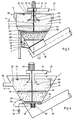
- a container 1 is provided which is vertical Axis 2 has.
- the container 1 is essentially rotationally symmetrical to axis 2.
- the container 1 has in its lower area a conically widening Wall part 3, which is a cylindrical upwards designed wall part 4 connects.
- the container 1 can with be provided with a cover 5.
- the diameter of the container can be one or more meters. Can be used for installation purposes Legs 6 may be provided.
- a perforated base 8 is horizontal aligned.
- the perforated floor 8 is double-walled educated.
- Its wall 9 facing upward has openings 10 on that in shape evenly over the area distributed nozzles can be formed.
- the after the bottom wall 11 is closed.
- a line 12 connected, in which a pump 13 is provided and via the liquid into the interior of the perforated base 8 between the Walls 9 and 11 is guided. This liquid passes through the openings 10 directed upwards in the container.
- a fluidized sand layer 14 is provided in the perforated base 8, which in through the outflowing from the perforated bottom 8 in Movement is kept.
- the sand layer 14 has an expansion height on, which goes up to a limit 15, which here as Dash is indicated.
- the moving grains of sand 16 in the Fluidized sand layer 14 are shown exaggeratedly large. Depending on the amount of sand in the container, there will be the fluidized sand layer 14 more or less upwards expand.
- Above the limit 15 of the sand layer 14 is a Collection space 17 for organic material 18 is provided.
- a Inlet pipe 21 opens tangentially into a swirl chamber 22 which follows below into a down pipe 23, on which a trumpet-shaped Diffuser 24 connects.
- the mixture of liquid, organic material and inorganic material is thus in a swirl flow according to arrow 25 introduced into the container 1 and is distributed more or less radially according to arrows 26 in the collecting room 17.
- the diffuser 24 is below the water level 27 arranged.
- the water level 27 turns according to an overflow 28 on a device 29 for removing the organic material 18 and the liquid.
- the overflow 28 leads to an exhaust pipe 30.
- a filler pipe 31 may be provided which penetrates the cover 5.
- a contaminated sand mixture, especially street sweepings, are then filled into the liquid arrives and is treated accordingly.
- the trigger device 32 can be in particular as Screw conveyor 33 with housing 34, shaft 35 and spiral conveyor 36 be formed. It is understood that a drive for the Screw conveyor 33 and the extraction device 32 are provided is operated continuously or discontinuously can, so that the inorganic material is withdrawn according to arrow 37 can be. So that the inorganic material, namely the itself in the area of the sand layer 40 enriching sand grains 16 the fluidized sand layer 14 can pass down and so that the perforated base 8 can pass is a bypass 38 provided, for example in the form of a perforated base 8 in vertical direction penetrating tube 39.
- the tube 39 is provided concentric to the axis 2 of the container, closes on the one hand the interior of the perforated base 8 between the walls 9 and 11 and on the other hand allows the passage of Grains of sand 16 from the area of the fluidized sand layer 14 in the area of the discharge device 32, so that on this Way there is the possibility of expanding the fluidized To keep the sand layer 14 constant up to the limit 15.
- An agitator 40 is concentric in the container 1 and to the axis 2 provided, which has a vertical shaft 41 which over a motor 42 is driven.
- the shaft 41 is with stirring arms 43 occupied, which are arranged just above the perforated base 8.
- One or more stirring arms 43 can be provided.
- the Stirring arms 43 cause in a relatively slow circulation that channels for a preferred inflow in the area of not fluidized sand layer 14 above the perforated bottom 8 can train or destroyed such channels immediately become.
- the sand grains 16 of the sand layer 14 are also here mechanically stressed by the agitator arms 43 and thus rubbed and cleaned.
- Additional stirring arms 44 can be attached to the shaft 41 be appropriate in association with the upper limit 15 of the Sand layer 14 and thus in the lower region of the collecting space 17th are arranged and act.
- These stirring arms 44 have the task an overly dense deposit of organic material 18 on the Prevent sand layer 14 and here also the organic Always keep material 18 moving, shredding and closing mix. On the one hand, this serves to ensure that those descending from above Grains of sand 16 penetrate the organic material 18 and can penetrate into the area of the sand layer 14.
- the buoyancy of further shredded organic material 18 improved so that this in the collection room 17 float and ultimately discharged via the overflow 28 can be.
- the device according to FIG. 1 can be operated as follows:
- the sand layer 14 is fluidized in the container 1. Via the pump 13 and the line 12, liquid from the Openings 9 of the perforated base 8 are carried upward, whereby the sand layer 14 expands accordingly and is held in this expansion. Now liquid is with organically contaminated inorganic material according to arrow 20 abandoned via the feeder 19 and comes under the water level 27 in a swirl-like distribution, like this is indicated by the arrows 25 and 26. Depending on the size of the Particles will move them in the collecting space 17. Larger ⁇ Particles sink faster than smaller particles. Grains of sand 16 will sink and into the area of the fluidized sand layer 14 arrive, which increases the amount of sand here elevated. Organic material 18 will be within the Moving collecting space 17, again larger particles sink faster than fine particles.
- the organic Material 18 will, however, to a large extent above the Pile border 15 on the sand layer 14. Fine organic Material 18 flows over the overflow 28 carried out while larger particles of organic matter be broken up and crushed until they also have one such a state of limbo that they are separated from that by the Perforated bottom 8 applied inflowing water with discharged become.
- the agitator 40 with its arms 43 and 44 contributes to Cleaning and movement of the respective layers.
- By the Tube 39 can grains of sand 16 from the sand layer 14 down step through. This cleaned sand is used with the discharge device 32 carried upwards and conveyed away. This happens in such a way that the expansion height of the sand layer 14 is kept as constant as possible up to the limit 15.
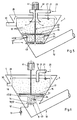
- the embodiment of the device according to FIG. 3 is broad Areas initially constructed similarly to the embodiment according to Figure 1, so that reference is made to the description here can be.
- the agitator 40 has a shorter one here designed shaft 41, on which only stirring arms 44 are provided which are just below the limit 15 of the fluidized sand layer 14 work.
- a support plate 45 is provided, although within the fluidized sand layer 14 is arranged, however, the support of material on their surface, which of the fluidized sand layer 14 is not detected.
- This yourself Superimposed material is moved together with the stirring arms 44 grated, crushed and separated, including one Promotional effect on this material occurs in such a way that it increasingly shifted to a larger radius and finally can pass over the edge 46 of the support plate 45.
- cleaned sand grains 16 act that fluidized in the Install layer of sand 14 while the organic material through the movement of the agitator arms 44 after its comminution in the Collection room 17 floats.
- the perforated base 8 is formed continuously here.
- a bypass 38 serves a bypass line 47 in the area of the sand layer 14 is connected to this, bypasses the perforated base 8 and in the lower region 7 of the container 1 opens, so that here passing sand discharged from the discharge device 32 can be.
- a valve 48 is arranged for control purposes.
- the embodiment of the device shown in Figure 4 has a container 1, which is from bottom to top conically widening cross section is formed. About one cylindrical overflow 28 is connected to the Discharge tube 30.
- the agitator 40 has agitator arms 43 and 44.
- electrical line 50 is connected to valve 48, which is centered here in the tube 39, which the perforated base 8th penetrates, is housed. With the pressure probe 49 static pressure in the area of the sand layer 14 is monitored.
- the valve 48 is opened and vice versa, so that the height of expansion the sand layer 14 are kept constant up to the limit 15 can. Due to the increasing cross-section from bottom to top of the container 1, the speed will decrease from the bottom Reduce above accordingly so that only organic material 18 is discharged in finely divided form over the overflow 28.
- the embodiment according to FIG Embodiment according to Figure 4 has a special feature. It is a Insert 51 is provided, which is essentially cylindrical and in its upper area into an annular surface 52 passes, which fulfills the function of the support plate 45. Also here is an assignment to the agitator arms 44 of the agitator 40 given. The diameter of the insert 51 and the diameter the perforated bottom 8 are adapted to each other. The fluidized Sand layer 14 extends essentially over the height of the Mission 51.
- This form of training has the advantage that the Insert 51 and an adapted perforated base 8 interchangeable in the Container 1 can be provided to different devices Sizes for different throughputs are available to deliver.
- the sand layer 14 is extended to the upper limit 15, so that here, as it were, two speed ranges Flow velocity formed within the sand bed 14 are.
- FIG. 6 shows the device according to FIG. 5, but with a Insert 51 comparatively smaller diameter and in Assignment to a perforated base 8, whose outer diameter is smaller is as the relevant diameter of the container 1 on this Job.
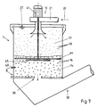
- the embodiment of the device according to FIG. 7 is correct largely with previously described embodiments of the device, so that reference can be made to this.
- the container 1 has a largely cylindrical here continuous housing, at least in the area of the sand layer 14 and the collecting space 17.
- the support plate 45 also works here with stirrer arms 44 of the stirrer 40 together.
- Figure 8 shows a plan view of the perforated base 8 with its upper wall 9, in which the nozzle-like openings 10 are evenly distributed.
- the pipe 39 is central provided which forms the bypass 38.
- Two cleaning lines 55 of a backwashing cleaning device 56 shown tangent to the interior of the Perforated bottom 8 is connected between the walls 9 and 11.
- Via a connection 57 which is only indicated schematically, sand, which penetrated into the perforated base 8 during normal operation is to be rinsed out, so that then the even Structure of the fluidized sand layer 14 in normal operation becomes possible again.
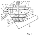
- FIG 9 shows a device which is based essentially on the Embodiment of Figure 5 builds. However, here is a first one Trigger device 58 is provided, with the substantially organic material in the liquid is drawn off. A second trigger device 59 is used essentially to deduct the Liquid, whereby here too organic material with the Liquid is drawn off.
- the device 29 is therefore in two separate discharge facilities, which is also useful operated differently.
- the trigger device 58 will preferably discontinuously and the trigger device 59 operated continuously.
- the separate first trigger device 58 serves to over-concentrate organic Avoid material in the collecting room 17, otherwise the danger there is that on the one hand, in particular with a large loading quantity the degree of contamination of the inorganic material the intended cleaning of the sand only increases insufficiently occurs, and on the other hand, fine sands increasingly the liquid are discharged.
- the separate first trigger device 58 provided that a fixed tube 60 can have, which the wall part 4 of the container 1 penetrates and thus immediately Has connection to the collection space 17 for the organic material.
- a valve 61 is expediently arranged to the discontinuous removal of the organic material according to arrow To enable 62.
- a suction line 63 which in dashed lines is indicated.
- the suction line 63 or you in the collection room 17 protruding end can be adjusted in height according to double arrow 65 be arranged to remove organic material in to allow different depths of the collecting space 17.
- the discontinuous removal of organic material can in particular when the Ruhrwerk 40 is at a standstill be so that even with the arrangement of a further stirring arm 66 suction of the shaft 41 in the region of the collecting space 17 can take place below this stirring arm 66.
- the device 29 can be divided into two separate extraction devices 58 and 59 in all embodiments of the device, the extraction device 58 always having to be arranged at a certain distance from the fluidized sand layer 14 in order to remove as little sand as possible when the organic material is removed.
Landscapes
- Separation Of Solids By Using Liquids Or Pneumatic Power (AREA)
- Devices And Processes Conducted In The Presence Of Fluids And Solid Particles (AREA)
- Organic Low-Molecular-Weight Compounds And Preparation Thereof (AREA)
- Fluidized-Bed Combustion And Resonant Combustion (AREA)
- Extraction Or Liquid Replacement (AREA)
Claims (13)
- Dispositif destiné à séparer d'un liquide une matière organique et une matière inorganique, en particulier des impuretés organiques et du sable provenant d'installations d'épuration, comprenant un récipient (1) de construction circulaire, qui présente à sa partie supérieure un dispositif de chargement (9) pour l'introduction du liquide ainsi que des matières organique et inorganique dans le récipient (1), comportant une dérivation (38) pour le transfert d'une partie de la matière inorganique dans un dispositif de soutirage (32) disposé dans la partie inférieure (7) du récipient (1) pour la matière inorganique ainsi qu'un dispositif (29) d'évacuation de la matière organique et du liquide, caractérise, en ce que pour séparer la matière organique de la matière inorganique et pour fragmenter la matière organique il est prévu, dans la partie inférieure (7) du récipient (1) une couche de sable fluidifiée (14), qui est maintenue en mouvement par un courant réparti sur un fond perforé (8) et dirigé vers le haut, en ce que le récipient (1) présente, à la suite de la limite supérieure (15) d'expansion de la couche de sable fluidifiée (14), une chambre collectrice (17) se raccordant par le haut pour la matière organique (18) et en ce que le dispositif (19) d'évacuation de la matière organique et du liquide comporte un premier dispositif d'évacuation (58) essentiellement pour la matière organique (18) provenant de la chambre collectrice (17) et un deuxième dispositif d'évacuation (59) essentiellement pour le liquide.
- Dispositif selon la revendication 1, caractérisé en ce que le dispositif de chargement (19) est disposé au centre et comporte une chambre à cyclone (22), un tube de descente (23) et un diffuseur (24) en forme de trompette.
- Dispositif selon la revendication 1, caractérisé en ce que la chambre collectrice pour la matière organique (18), qui fait suite vers le haut à la limtite supérieure (15) d'expansion de la couche de sable fuidifiée (14), présente une section s'élargissant vers le haut.
- Dispositif selon l'une des revendications 1 à 3, caractérisé en ce que dans le récipient (1) est prévu un agitateur (40), qui comporte des bras d'agitation (43, 44), qui sont montés à rotation dans la partie inférieure de la couche de sable fluidifiée (14), directement au-dessus du fond perforé et/ou au-dessus de la couche de sable fluidifiée, à la suite de la limite entre la couche de sable fluidifiée (14) et la chambre collectrice (17) pour la matière organique.
- Dispositif selon la revendication 4, caractérisé en ce que dans le récipient (1) est prévue une plaque de support (20) orientée horizontalement à surface fermée, qui est associée à un bras d'agitation (44) de l'agitateur (40).
- Dispositif selon la revendication 1, caractérisé en ce que le fond perforé (8) est à double paroi, en ce qu'il présente dans sa paroi (9) dirigée vers le haut un grand nombre d'ajours (10) répartis uniformément sur sa surface, tandis que sa paroi inférieure (11) est fermée, et en ce qu'il est prévu comme dérivation (38) un tube (39) traversant verticalement le fond perforé (8).
- Dispositif selon la revendication 6, caractérisé en ce que le fond perforé (8) à double paroi est raccordé, pour produire le courant dirigé vers le haut, pour la fluidification de la couche de sable (14), à une conduite (12) comportant une pompe (13) pour le liquide.
- Dispositif selon l'une des revendications 1 à 7, caractérisé en ce que dans le récipient (1) est prévu un insert (51) à peu près cylindrique, auquel est associé le fond perforé (8) et qui sert à limiter l'expansion de la couche de sable fluidifiée (14).
- Dispositif selon l'une des revendications 1 à 8, caractérisé en ce que la couche de sable fluidifiée (14) présente une hauteur d'expansion d'environ 20 à 40 cm.
- Dispositif selon la revendication 6 ou 9, caractérisé en ce que dans le tube (39), qui traverse le fond perforé (8), il est prévu une vanne (48) et dans le récipient (1), il est prévu une sonde de pression (49) en liaison avec la couche de sable fluidifiée (14), et en ce que la vanne (48) est commandable par la sonde de pression (49), pour maintenir constante la hauteur d'expansion de la couche de sable fluidifiée (14).
- Dispositif selon la revendication 6, caractérisé en ce que le fond perforé (8) est pourvu d'un dispositif de nettoyage (56) par lavage à contre-courant.
- Dispositif selon la revendication 1, caractérisé en ce que le premier dispositif de soutirage (58) pour la matière organique comporte un tube (60) traversant la partie de paroi (4) du récipient (1), dans la région de la chambre collectrice (17).
- Dispositif selon la revendication 1, caractérisé en ce que le premier dispositif de soutirage (58) pour la matière organique comporte une conduite d'aspiration (63) pénétrant à peu près verticalement dans la chambres collectrice (17).
Applications Claiming Priority (3)
| Application Number | Priority Date | Filing Date | Title |
|---|---|---|---|
| DE4415647 | 1994-05-04 | ||
| DE4415647A DE4415647C2 (de) | 1994-05-04 | 1994-05-04 | Vorrichtung zum Abtrennen von mit organischem Material verschmutztem anorganischem Material aus einer Flüssigkeit |
| PCT/EP1994/003167 WO1995030486A1 (fr) | 1994-05-04 | 1994-09-22 | Dispositif permettant de separer d'un liquide un materiau inorganique pollue par un materiau organique |
Publications (2)
| Publication Number | Publication Date |
|---|---|
| EP0707520A1 EP0707520A1 (fr) | 1996-04-24 |
| EP0707520B1 true EP0707520B1 (fr) | 1999-04-21 |
Family
ID=6517222
Family Applications (1)
| Application Number | Title | Priority Date | Filing Date |
|---|---|---|---|
| EP94928796A Expired - Lifetime EP0707520B1 (fr) | 1994-05-04 | 1994-09-22 | Dispositif permettant de separer d'un liquide un materiau inorganique pollue par un materiau organique |
Country Status (6)
| Country | Link |
|---|---|
| US (1) | US5641397A (fr) |
| EP (1) | EP0707520B1 (fr) |
| JP (1) | JP3634374B2 (fr) |
| AT (1) | ATE179095T1 (fr) |
| DE (2) | DE4415647C2 (fr) |
| WO (1) | WO1995030486A1 (fr) |
Cited By (1)
| Publication number | Priority date | Publication date | Assignee | Title |
|---|---|---|---|---|
| EP1516672A1 (fr) | 2003-09-22 | 2005-03-23 | Hans Huber AG Maschinen- und Anlagenbau | Dispositif pour la séparation de matière organique de matière inorganique |
Families Citing this family (29)
| Publication number | Priority date | Publication date | Assignee | Title |
|---|---|---|---|---|
| DE19622962A1 (de) * | 1996-06-07 | 1997-12-11 | Gerd Meurer Abwassertechnik Gm | Vorrichtung zum Trennen von in Flüssigkeit aufgeschwemmtem Verbundmaterial |
| DE29614456U1 (de) * | 1996-08-21 | 1996-11-14 | Feierabend, Andreas, 45326 Essen | Vorrichtung zum Reinigen und Abtrennen von Sand aus einem Sand/Flüssigkeitsgemisch, insbesondere Sand/Wassergemisch |
| SG54572A1 (en) * | 1996-10-04 | 1998-11-16 | Nihon Genryo Co Ltd | Sand washing apparatus |
| US6273106B1 (en) | 1996-10-04 | 2001-08-14 | Nihon Genryo Co., Ltd. | Particulate matter washing apparatus and method |
| DE19823674A1 (de) * | 1998-05-20 | 1999-12-02 | Alfred Schymalla | Vorrichtung zur Entfernung organischer Bestandteile aus Sand |
| DE19924164C2 (de) * | 1999-02-18 | 2001-04-12 | Bormet Maschb Gmbh | Verfahren und Vorrichtung zur Separation von aus organischem und anorganischem Material zusammengesetzten Feststoffen aus einer mit Feststoffen vermischten Flüssigkeit und zur Abtrennung des anorganischen Materials aus dem Gemisch von organischen und anorganischem Material |
| RU2166372C2 (ru) * | 1999-07-06 | 2001-05-10 | Открытое акционерное общество "Рудгормаш" | Гидравлический классификатор |
| RU2174447C2 (ru) * | 1999-08-30 | 2001-10-10 | ЗАО "Центртехнометалл" | Гидравлический классификатор |
| EP1123723A1 (fr) * | 2000-02-10 | 2001-08-16 | Fernando H. Garcia | Dispositif de séparation des particules solides d'un liquide |
| DE10014944A1 (de) * | 2000-03-21 | 2001-10-04 | Berliner Wasserbetriebe | Rechengutaufbereitungsanlage |
| SE518295C2 (sv) * | 2000-10-12 | 2002-09-17 | Laeckeby Water Ab | Förfarande och anordning för avskiljning av lättare partiklar från tyngre partiklar i en vätska |
| FR2815714B1 (fr) * | 2000-10-20 | 2003-01-03 | Omnium Traitement Valorisa | Installation de mesure de la concentration en materiau granulaire dense d'un ecoulement et systeme pour le traitement de l'eau incluant une telle installation |
| DE20112681U1 (de) | 2001-08-08 | 2001-10-18 | Egner Umwelttechnologie GmbH, 74740 Adelsheim | Vorrichtung zur Behandlung eines Feststoff-Flüssigkeitsgemisches |
| US6668625B2 (en) * | 2001-10-26 | 2003-12-30 | Smith & Loveless, Inc. | Measurement of the level of settled particles within a fluid vessel |
| DE10200599B4 (de) * | 2002-01-10 | 2005-12-15 | Hans Huber Ag Maschinen- Und Anlagenbau | Vorrichtung zum Abscheiden von organischem und anorganischem Material aus einer Flüssigkeit |
| US6966987B1 (en) * | 2002-01-11 | 2005-11-22 | Process Efficiency Products, Inc. | Tangentially fed media filter method and apparatus |
| RU2246996C2 (ru) * | 2002-12-25 | 2005-02-27 | Верхотуров Михаил Васильевич | Концентратор гравитационный |
| JP4563073B2 (ja) * | 2003-05-29 | 2010-10-13 | 正明 岡島 | 汚泥の洗浄方法ならびにその装置 |
| DE10361786A1 (de) * | 2003-12-31 | 2005-02-17 | Kuhn, Jürgen | Vorrichtung zum Trennen von mit organischem Material verschmutzten anorganischem Material aus einer Schmutzflüssigkeit |
| US20070221552A1 (en) * | 2004-05-18 | 2007-09-27 | Biomass Processing Technology, Inc. | System for Processing a Biomaterial Waste Stream |
| DE102005048053A1 (de) * | 2005-10-07 | 2007-04-12 | Voith Patent Gmbh | Messvorrichtung, insbesondere zur Messung von Entwässerungsmengen von Papiermaschinen |
| EP2001596A4 (fr) * | 2006-03-20 | 2014-02-19 | Parkson Corp | Méthode et appareil de nettoyage de sable |
| FR2910822B1 (fr) * | 2006-12-29 | 2009-02-27 | Otv Sa | Procede et installation de traitement d'eau par floculation lestee et decantation |
| DE102010010572A1 (de) * | 2010-03-08 | 2011-09-08 | Mahle International Gmbh | Trockenseparator |
| WO2014183804A1 (fr) * | 2013-05-17 | 2014-11-20 | Stigebrandt Hydroteknik Ab | Séparateur et procédé de séparation de particules solides à partir de liquides |
| GB2556038A (en) * | 2016-11-10 | 2018-05-23 | Henry Coulton Richard | Separator apparatus and method |
| CN110743247A (zh) * | 2019-12-07 | 2020-02-04 | 新晃县污水处理有限责任公司 | 一种污水沉砂装置 |
| CN113800713B (zh) * | 2021-09-08 | 2024-01-09 | 黑龙江省捷浩建筑工程有限公司 | 一种生活污水处理装置及处理方法 |
| EP4628183A1 (fr) * | 2024-04-02 | 2025-10-08 | Stjernholm A/S | Installation de séparation de sable-liquide, utilisation de cette installation et procédé d'utilisation de cette installation |
Family Cites Families (9)
| Publication number | Priority date | Publication date | Assignee | Title |
|---|---|---|---|---|
| FR1386847A (fr) * | 1964-03-24 | 1965-01-22 | Dorr Oliver Inc | Appareil de classement hydraulique de commande automatique d'un siphon |
| US3579443A (en) * | 1969-07-31 | 1971-05-18 | Russell J Horst | Formation of dense precipitates |
| US3940252A (en) * | 1972-03-27 | 1976-02-24 | Deutsche Gold- Und Silber-Scheideanstalt Vormals Roessler | Apparatus for the releasing of materials from voluminous precipitates or suspensions |
| JPS6052111B2 (ja) * | 1979-03-02 | 1985-11-18 | 日本化学工業株式会社 | 肥料造粒物の製造法 |
| AT359009B (de) * | 1979-06-20 | 1980-10-10 | Szilikat Koezponti Kutato | Hydraulische vibrations-entwaesserungs- einrichtung |
| JPS5742354A (en) * | 1980-08-25 | 1982-03-09 | Nagata Seisakusho:Kk | Sorting device for granulated slag |
| SU1452586A1 (ru) * | 1986-12-29 | 1989-01-23 | Волжский Абразивный Завод | Гидравлический классификатор |
| DE4118020A1 (de) * | 1991-06-01 | 1992-12-03 | Schauenburg Masch | Verfahren zum abscheiden spezifisch leichter bestandteile aus einer truebe durch aufstromsortierung und messvorrichtung dazu |
| DE4224047C2 (de) * | 1992-07-21 | 1998-03-26 | Anton Felder | Vorrichtung und Verfahren zur zentrischen Beschickung von Rundsandfängen und Sandklassierern in Rundbauweise |
-
1994
- 1994-05-04 DE DE4415647A patent/DE4415647C2/de not_active Expired - Lifetime
- 1994-09-22 DE DE59408147T patent/DE59408147D1/de not_active Expired - Lifetime
- 1994-09-22 EP EP94928796A patent/EP0707520B1/fr not_active Expired - Lifetime
- 1994-09-22 WO PCT/EP1994/003167 patent/WO1995030486A1/fr not_active Ceased
- 1994-09-22 AT AT94928796T patent/ATE179095T1/de active
- 1994-09-22 JP JP52860895A patent/JP3634374B2/ja not_active Expired - Fee Related
- 1994-09-22 US US08/564,325 patent/US5641397A/en not_active Expired - Lifetime
Cited By (2)
| Publication number | Priority date | Publication date | Assignee | Title |
|---|---|---|---|---|
| EP1516672A1 (fr) | 2003-09-22 | 2005-03-23 | Hans Huber AG Maschinen- und Anlagenbau | Dispositif pour la séparation de matière organique de matière inorganique |
| US7318527B2 (en) | 2003-09-22 | 2008-01-15 | Hans Huber Ag Maschinen-Und Anlagenbau | Apparatus for separating organic material from inorganic material |
Also Published As
| Publication number | Publication date |
|---|---|
| DE4415647C2 (de) | 1996-10-02 |
| JPH08512246A (ja) | 1996-12-24 |
| WO1995030486A1 (fr) | 1995-11-16 |
| DE59408147D1 (de) | 1999-05-27 |
| ATE179095T1 (de) | 1999-05-15 |
| EP0707520A1 (fr) | 1996-04-24 |
| US5641397A (en) | 1997-06-24 |
| DE4415647A1 (de) | 1996-02-15 |
| JP3634374B2 (ja) | 2005-03-30 |
Similar Documents
| Publication | Publication Date | Title |
|---|---|---|
| EP0707520B1 (fr) | Dispositif permettant de separer d'un liquide un materiau inorganique pollue par un materiau organique | |
| DE3885471T2 (de) | Zentrifugale Verdichtungsmaschine. | |
| DE2201188C3 (de) | Verfahren und Vorrichtung zum Abtrennen von Teilchen aus einer Flüssigkeit in einem Becken | |
| DE903681C (de) | Verfahren und Vorrichtung zum Sieben auf nassem Wege | |
| EP0592508B1 (fr) | Procede et dispositif pour l'amelioration du traitement de matieres solides contenues dans les eaux usees, de sable, de dechets ou similaires | |
| DE1642780A1 (de) | Verfahren und Vorrichtung zum Reinigen und Fraktionieren von Suspensionen | |
| DE2737009A1 (de) | Vorrichtung zur reinigung von faserstoffsuspensionen | |
| EP1516672B1 (fr) | Procédé et dispositif pour la séparation de matière organique de matière inorganique | |
| DE1507697A1 (de) | Verfahren und Vorrichtung zu rotierender Verarbeitung und Sortierung | |
| DE69505850T2 (de) | Mineralien-trenner | |
| DE1931978A1 (de) | Vorrichtung zur Behandlung von Schlammwasser | |
| DE2133802A1 (de) | Verfahren zur aufbereitung von mineralischen korngemengen nach der dichte und vorrichtung zur durchfuehrung des verfahrens | |
| DE2630639C3 (de) | Setzverfahren und -maschine zur Sortierung von Mineralkörnermischungen unterschiedlichen spezifischen Gewichts | |
| WO2012059415A1 (fr) | Appareil de flottation et procédé de flottation | |
| DE3732008A1 (de) | Verfahren zur aufbereitung von schadstoff-belasteten, insbesondere stichfesten sedimenten aus abwasserkanaelen und deren einrichtungen sowie von artverwandten stoffen und anlage zur durchfuehrung des verfahrens | |
| DE19844006A1 (de) | Sandwäsche | |
| DE19622962A1 (de) | Vorrichtung zum Trennen von in Flüssigkeit aufgeschwemmtem Verbundmaterial | |
| EP0012461B1 (fr) | Installation de gazéification de charbon | |
| DE19617501C2 (de) | Verfahren zur Trennung der Bestandteile von kommunalen Reststoffen | |
| CH644029A5 (de) | Verfahren und vorrichtung zum sammeln und entfernen von schwebstoffen und kompakten verunreinigungen aus einer suspension. | |
| DE4312540C1 (de) | Verfahren zur Abtrennung von Feststoffen aus einer Suspension sowie Vorrichtung zu seiner Durchführung | |
| EP0949948A1 (fr) | Procede et dispositif de filtration en continu de liquides | |
| DE2349941A1 (de) | Verfahren und vorrichtung zur nassfeinsiebung | |
| DE4410969C1 (de) | Vorrichtung zum Trennen von leichtlöslichen Stoffen, Schwebestoffen und schwerlöslichen Stoffen aus einem Feststoff- oder Flüssigkeit-Feststoffgemisch | |
| DE19721629C1 (de) | Aufstromsortierer |
Legal Events
| Date | Code | Title | Description |
|---|---|---|---|
| PUAI | Public reference made under article 153(3) epc to a published international application that has entered the european phase |
Free format text: ORIGINAL CODE: 0009012 |
|
| 17P | Request for examination filed |
Effective date: 19960216 |
|
| AK | Designated contracting states |
Kind code of ref document: A1 Designated state(s): AT CH DE FR GB LI NL SE |
|
| 17Q | First examination report despatched |
Effective date: 19980316 |
|
| GRAG | Despatch of communication of intention to grant |
Free format text: ORIGINAL CODE: EPIDOS AGRA |
|
| GRAG | Despatch of communication of intention to grant |
Free format text: ORIGINAL CODE: EPIDOS AGRA |
|
| GRAH | Despatch of communication of intention to grant a patent |
Free format text: ORIGINAL CODE: EPIDOS IGRA |
|
| GRAH | Despatch of communication of intention to grant a patent |
Free format text: ORIGINAL CODE: EPIDOS IGRA |
|
| GRAA | (expected) grant |
Free format text: ORIGINAL CODE: 0009210 |
|
| AK | Designated contracting states |
Kind code of ref document: B1 Designated state(s): AT CH DE FR GB LI NL SE |
|
| REF | Corresponds to: |
Ref document number: 179095 Country of ref document: AT Date of ref document: 19990515 Kind code of ref document: T |
|
| REG | Reference to a national code |
Ref country code: CH Ref legal event code: NV Representative=s name: DR. CONRAD A. RIEDERER PATENTANWALT Ref country code: CH Ref legal event code: EP |
|
| GBT | Gb: translation of ep patent filed (gb section 77(6)(a)/1977) |
Effective date: 19990421 |
|
| REF | Corresponds to: |
Ref document number: 59408147 Country of ref document: DE Date of ref document: 19990527 |
|
| ET | Fr: translation filed | ||
| PLBE | No opposition filed within time limit |
Free format text: ORIGINAL CODE: 0009261 |
|
| STAA | Information on the status of an ep patent application or granted ep patent |
Free format text: STATUS: NO OPPOSITION FILED WITHIN TIME LIMIT |
|
| 26N | No opposition filed | ||
| REG | Reference to a national code |
Ref country code: GB Ref legal event code: IF02 |
|
| REG | Reference to a national code |
Ref country code: CH Ref legal event code: NV Representative=s name: RIEDERER HASLER & PARTNER PATENTANWAELTE AG |
|
| PGFP | Annual fee paid to national office [announced via postgrant information from national office to epo] |
Ref country code: NL Payment date: 20090923 Year of fee payment: 16 |
|
| REG | Reference to a national code |
Ref country code: NL Ref legal event code: V1 Effective date: 20110401 |
|
| PG25 | Lapsed in a contracting state [announced via postgrant information from national office to epo] |
Ref country code: NL Free format text: LAPSE BECAUSE OF NON-PAYMENT OF DUE FEES Effective date: 20110401 |
|
| PGFP | Annual fee paid to national office [announced via postgrant information from national office to epo] |
Ref country code: SE Payment date: 20120925 Year of fee payment: 19 Ref country code: GB Payment date: 20120925 Year of fee payment: 19 |
|
| PGFP | Annual fee paid to national office [announced via postgrant information from national office to epo] |
Ref country code: DE Payment date: 20120613 Year of fee payment: 19 |
|
| PGFP | Annual fee paid to national office [announced via postgrant information from national office to epo] |
Ref country code: CH Payment date: 20121001 Year of fee payment: 19 Ref country code: FR Payment date: 20121011 Year of fee payment: 19 |
|
| PGFP | Annual fee paid to national office [announced via postgrant information from national office to epo] |
Ref country code: AT Payment date: 20120924 Year of fee payment: 19 |
|
| REG | Reference to a national code |
Ref country code: SE Ref legal event code: EUG |
|
| PG25 | Lapsed in a contracting state [announced via postgrant information from national office to epo] |
Ref country code: SE Free format text: LAPSE BECAUSE OF NON-PAYMENT OF DUE FEES Effective date: 20130923 |
|
| REG | Reference to a national code |
Ref country code: CH Ref legal event code: PL |
|
| REG | Reference to a national code |
Ref country code: AT Ref legal event code: MM01 Ref document number: 179095 Country of ref document: AT Kind code of ref document: T Effective date: 20130922 |
|
| GBPC | Gb: european patent ceased through non-payment of renewal fee |
Effective date: 20130922 |
|
| REG | Reference to a national code |
Ref country code: FR Ref legal event code: ST Effective date: 20140530 |
|
| REG | Reference to a national code |
Ref country code: DE Ref legal event code: R119 Ref document number: 59408147 Country of ref document: DE Effective date: 20140401 |
|
| PG25 | Lapsed in a contracting state [announced via postgrant information from national office to epo] |
Ref country code: GB Free format text: LAPSE BECAUSE OF NON-PAYMENT OF DUE FEES Effective date: 20130922 Ref country code: LI Free format text: LAPSE BECAUSE OF NON-PAYMENT OF DUE FEES Effective date: 20130930 Ref country code: CH Free format text: LAPSE BECAUSE OF NON-PAYMENT OF DUE FEES Effective date: 20130930 |
|
| PG25 | Lapsed in a contracting state [announced via postgrant information from national office to epo] |
Ref country code: FR Free format text: LAPSE BECAUSE OF NON-PAYMENT OF DUE FEES Effective date: 20130930 Ref country code: AT Free format text: LAPSE BECAUSE OF NON-PAYMENT OF DUE FEES Effective date: 20130922 Ref country code: DE Free format text: LAPSE BECAUSE OF NON-PAYMENT OF DUE FEES Effective date: 20140401 |