EP1516672A1 - Dispositif pour la séparation de matière organique de matière inorganique - Google Patents
Dispositif pour la séparation de matière organique de matière inorganique Download PDFInfo
- Publication number
- EP1516672A1 EP1516672A1 EP04021875A EP04021875A EP1516672A1 EP 1516672 A1 EP1516672 A1 EP 1516672A1 EP 04021875 A EP04021875 A EP 04021875A EP 04021875 A EP04021875 A EP 04021875A EP 1516672 A1 EP1516672 A1 EP 1516672A1
- Authority
- EP
- European Patent Office
- Prior art keywords
- container
- inorganic material
- lifting device
- sand
- fluidized layer
- Prior art date
- Legal status (The legal status is an assumption and is not a legal conclusion. Google has not performed a legal analysis and makes no representation as to the accuracy of the status listed.)
- Granted
Links
- 239000011147 inorganic material Substances 0.000 title claims abstract description 43
- 229910010272 inorganic material Inorganic materials 0.000 title claims abstract description 41
- XLYOFNOQVPJJNP-UHFFFAOYSA-N water Substances O XLYOFNOQVPJJNP-UHFFFAOYSA-N 0.000 claims abstract description 63
- 239000011368 organic material Substances 0.000 claims abstract description 38
- 238000005406 washing Methods 0.000 claims abstract description 29
- 239000004576 sand Substances 0.000 claims description 58
- 230000001681 protective effect Effects 0.000 claims description 25
- 239000000523 sample Substances 0.000 claims description 7
- 238000003756 stirring Methods 0.000 claims description 7
- 238000000926 separation method Methods 0.000 claims description 5
- 239000010865 sewage Substances 0.000 claims description 3
- 239000010410 layer Substances 0.000 description 35
- 230000033001 locomotion Effects 0.000 description 21
- 239000000203 mixture Substances 0.000 description 9
- 230000000694 effects Effects 0.000 description 7
- 239000000463 material Substances 0.000 description 7
- 238000004140 cleaning Methods 0.000 description 5
- 239000013505 freshwater Substances 0.000 description 3
- 239000007788 liquid Substances 0.000 description 3
- 239000012044 organic layer Substances 0.000 description 3
- 239000000126 substance Substances 0.000 description 3
- 241001417527 Pempheridae Species 0.000 description 2
- 230000005540 biological transmission Effects 0.000 description 2
- 230000005587 bubbling Effects 0.000 description 2
- 230000005465 channeling Effects 0.000 description 2
- 230000003993 interaction Effects 0.000 description 2
- 238000004519 manufacturing process Methods 0.000 description 2
- 239000005416 organic matter Substances 0.000 description 2
- 230000001174 ascending effect Effects 0.000 description 1
- 230000015572 biosynthetic process Effects 0.000 description 1
- 238000004891 communication Methods 0.000 description 1
- 238000010276 construction Methods 0.000 description 1
- 230000001276 controlling effect Effects 0.000 description 1
- 230000003247 decreasing effect Effects 0.000 description 1
- 230000008021 deposition Effects 0.000 description 1
- 238000009826 distribution Methods 0.000 description 1
- 238000000605 extraction Methods 0.000 description 1
- 238000011086 high cleaning Methods 0.000 description 1
- 229910052500 inorganic mineral Inorganic materials 0.000 description 1
- 238000012423 maintenance Methods 0.000 description 1
- 238000000034 method Methods 0.000 description 1
- 239000011707 mineral Substances 0.000 description 1
- 150000002894 organic compounds Chemical class 0.000 description 1
- 239000002245 particle Substances 0.000 description 1
- 230000001105 regulatory effect Effects 0.000 description 1
- 230000000630 rising effect Effects 0.000 description 1
- 239000007787 solid Substances 0.000 description 1
- 230000029305 taxis Effects 0.000 description 1
- 238000011144 upstream manufacturing Methods 0.000 description 1
- 239000002351 wastewater Substances 0.000 description 1
Images


Classifications
-
- B—PERFORMING OPERATIONS; TRANSPORTING
- B01—PHYSICAL OR CHEMICAL PROCESSES OR APPARATUS IN GENERAL
- B01D—SEPARATION
- B01D21/00—Separation of suspended solid particles from liquids by sedimentation
- B01D21/24—Feed or discharge mechanisms for settling tanks
- B01D21/245—Discharge mechanisms for the sediments
- B01D21/2461—Positive-displacement pumps; Screw feeders; Trough conveyors
-
- B—PERFORMING OPERATIONS; TRANSPORTING
- B03—SEPARATION OF SOLID MATERIALS USING LIQUIDS OR USING PNEUMATIC TABLES OR JIGS; MAGNETIC OR ELECTROSTATIC SEPARATION OF SOLID MATERIALS FROM SOLID MATERIALS OR FLUIDS; SEPARATION BY HIGH-VOLTAGE ELECTRIC FIELDS
- B03B—SEPARATING SOLID MATERIALS USING LIQUIDS OR USING PNEUMATIC TABLES OR JIGS
- B03B13/00—Control arrangements specially adapted for wet-separating apparatus or for dressing plant, using physical effects
-
- B—PERFORMING OPERATIONS; TRANSPORTING
- B03—SEPARATION OF SOLID MATERIALS USING LIQUIDS OR USING PNEUMATIC TABLES OR JIGS; MAGNETIC OR ELECTROSTATIC SEPARATION OF SOLID MATERIALS FROM SOLID MATERIALS OR FLUIDS; SEPARATION BY HIGH-VOLTAGE ELECTRIC FIELDS
- B03B—SEPARATING SOLID MATERIALS USING LIQUIDS OR USING PNEUMATIC TABLES OR JIGS
- B03B5/00—Washing granular, powdered or lumpy materials; Wet separating
- B03B5/62—Washing granular, powdered or lumpy materials; Wet separating by hydraulic classifiers, e.g. of launder, tank, spiral or helical chute concentrator type
- B03B5/623—Upward current classifiers
Definitions
- the invention relates to a device for separating organic material from inorganic material, in particular of organically polluted sand from sewage treatment plants, with a container having in its upper part a charging device for the Introduction of contaminated inorganic material in the container, with an im Lower portion of the container arranged withdrawal device for the separated inorganic material, a device for removing the organic material and a Supply means for washing water in the lower region of the container, wherein above the Supply means for washing water in the container, the separation of the organic material from the inorganic material is carried out in a fluidized layer.
- the container of Device may in particular in round design, but also with polygonal cross-section to be created. It has a vertical axis and can be cylindrical as well be conical sections composed.
- the device is used for washing the organically polluted Sand. By separating the organic material, the inorganic material, So the sand, cleaned. The separated organic material may be used together with the Wash water, but alternatively also deducted via a separate extraction device become.
- the material which from the sand trap of sewage treatment plants or in the Sewer cleaning is taken from the sewer system, but also street sweeper, as he from Sweeper is included, in addition to the inorganic material in the form of Sand, stones and the like often considerable amounts of organic material. To that supply inorganic material to a landfill site or otherwise reuse it can, it must be freed to some extent of the organic material to to carry out a cost-effective disposal.
- a device of the type described above is known from DE 44 15 647 C2 or the EP 0 707 520 B1.
- the device has a container with a vertical axis. Of the Container has a section extending from bottom to top in sections.
- a loading device for the introduction of the polluted inorganic material provided in the container.
- a discharge device for the separated purified inorganic material, which consists of an obliquely upward guided screw conveyor.
- a supply device for Washing water provided, which has a hole bottom.
- the hole bottom has a Variety over the cross section distributed openings, nozzles or the like, so that with its help one distributed over the cross section and upwards directed flow is generated.
- the wash water is in such an amount per Time unit supplied and distributed over the openings of the bottom plate directed upward delivered that above the hole bottom, a fluidized layer is formed, so a Fluidized bed, through which the organically polluted inorganic material in the for a Fluidized bed is added to typical state of motion, in which the grains of sand always rebound against each other and against the wall of the container, so that the adhered organic material is detached from the inorganic material.
- the generated fluidized bed is fundamentally different from a stirred one Fixed bed, in which the grains of sand can not move freely.
- the generated fluidized layer typically has a certain amount of expansion in the container, the is monitored by means of a pressure cell.
- the signals of the pressure cell can be used to the discharge device for the separated inorganic material Taxes. So that the deduction material can get into the area of the trigger device is a bypass is provided, which can be technically realized in a variety of ways, For example, by an opening in the central region of the bottom plate, the arrangement of a Bypass or other opening, through which also the washing water upwards and the cleaned sand in the opposite direction can pass down.
- an agitator is arranged, which has stirring arms, which in the lower part of the fluidized sand layer and / or in the lower part of a plenum for the organic material can be arranged.
- the known device can be a effective separation between organic and inorganic material cause.
- the fluidized layer is generated solely by the supplied wash water, so that this must be provided in an appropriate amount per unit of time.
- the empty pipe speed of the upstream water is about 5 to 15 m / h.
- the stirring arms of the agitator, in the lower part of the fluidized sand layer and / or in the lower Area of the collecting space for the organic material are arranged circumferentially, prevent on the one hand channeling in the lower part of the fluidized sand view and On the other hand, loosen over the organic layer on the sand layer, so that on the feeder further added contaminated material the penetrate organic layer and thus into the area of the fluidized sand layer can get.
- EP 0 713 418 B1 discloses a method and an apparatus for separating sand of waste water loaded with sand and organic matter in a vertical container known.
- a charging device is provided in the upper region of the container.
- a removal device for the separated inorganic material in the form of a screw conveyor.
- a fresh water supply via the fresh water in a circulating flow is added, in which the specifically lighter organic substances up to a Overflow while the specific heavier grains of sand against the Fall down the bottom of the container and form a sand cake there, which is stirred by a stirrer is stirred mechanically, so that the individual grains of sand rub against each other and thereby if necessary, adhering organic substances are rubbed off.
- the abraded organic Substances are produced with the aid of the up-flow produced by the supplied fresh water Flow taken up. This will make the polluted sand in the Fixed bed stirred mechanically and discharged only in an amount that a predetermined minimum height of the settled sand ensures.
- the cleaning effect is based essentially on the mechanical movement of the grains of sand in a fixed bed over the agitator, which must be designed with appropriate performance.
- From DE 198 44 006 A1 is a deposition of mineral sand from a known to be treated mixture of water, organic compounds and sand.
- the Mixture which is introduced from above into a settling tank, is filled with fine-bubbled air bubbled from bottom to top, so that in the vertical direction a separation of the particles according to their density. Due to the higher density of the deposited sand regulated dissipated.
- the mixture of sand, water and organic matter can be additionally mechanically stirred during the air bubbling.
- the in the ground area Sand deposited in a fixed bed can be used while stirring To determine the torque to be entered.
- the fluidity of the mixture can by additional water addition can be controlled from above.
- the device can do the job a sand separator / sand trap with take over.
- the invention is based on the object, a device of the type described above educate so that a high cleaning effect is achieved by the on the inorganic material adhering organic material is largely solved by this and subsequently the organic material on the one hand and the inorganic material on the other On the other hand can be removed separately. It all depends on a simple one To allow construction and an inexpensive manufacture of the device.
- the device works, as in the prior art, with a fluidized bed to the in the Compared to a fixed bed more effective separation between inorganic material and to carry out adhering organic material. So it will be at the bottom of the Container maintain a fluidized sand layer as a fluidized bed, the thereby initiated movement of the grains of sand leads to the organic material of inorganic material detached, crushed and through the wash water to the top is discharged.
- the fluidized bed is not just by the addition of wash water generated and maintained. Rather, it is additionally a lifting device provided, which together with the supply means for the washing water in the lower Area of the container generates the fluidized layer.
- the lifting device provides a Movement component on the grains of sand vertically upwards, ie in the same Direction in which also the supplied wash water a vertical component of movement on the grains of sand. It is initiated a circulating flow in the fluidized bed and so in Areas of the fluidized bed generates a countercurrent wash. Since the lifting device for Creation and maintenance of the fluidized bed, advantageously results in the Possibility of lower water consumption of the washing water supply. The interpretation the device can be made so that the wash water supply alone a Exceeding the vortex point is not yet possible, but this vertical Movement component of the lifting device is required.
- the device can be used with advantage even then, when relatively small amounts of inorganic material polluted with organic material Material should be separated from each other.
- the lifting device applies to the mixture of inorganic and organic material in the region of the fluidized bed an upward Movement component off. It clearly differs from one Agitator, which on the grains of sand a substantially horizontally directed Movement component exercises.
- the additional use of a lifting device has the Another advantage that the fluidized bed by the circulating flow described predetermined trajectory is moved. This will be a channeling, as for a Working in a fixed bed is typical, counteracted from the outset.
- a particularly simple and inexpensive realization of the lifting device results from a vertically arranged in the center of the container screw conveyor, via a shaft is driven.
- the shaft protrudes from above into the container, making the drive easier Way above the container and thus located outside the water level.
- the Lifting device in the form of such a screw conveyor can simultaneously with stirring arms be provided so that a jointly drivable unit is created here, the perform both the function of the lifting device as well as the function of a stirrer can.
- For the Abinstituts Koch is not the arrangement of a stirrer required.
- the lifting device can, as shown by the example of a screw conveyor, as mechanical be working device designed. This is effective in the center or in one arranged central ring portion of the container, preferably in such an area the container, which forms a cylindrical vertical section. But it is also possible to design the lifting device as a pneumatic device equipped with a gas, For example, with air, works, so that the lifting device is a compressed air lift.
- the supply of air is expediently from above.
- the air is at the bottom of the Fluidized bed brought specifically to flow, so below the water level, so that through the air on the organic and inorganic material a vertical component of motion which, together with the wash water supply, generates and Maintaining the fluidized bed allows.
- the lifting device can also Part of an agitator with driven from above shaft, wherein the lifting device primarily has to provide a vertical component of motion, while the horizontal movement component of the agitator is used only in addition.
- the device has a supply device for washing water, which is approximately as annular Line is formed with outlet openings.
- This feeder is different designed as known in the prior art hole bottom with upwardly directed nozzle-shaped openings which are arranged distributed over the cross-sectional area. Such nozzle-shaped openings can become dirty or even clogged, leaving a partial Closure of the bottom plate is possible.
- the feeder in the form of an annular Line with outlet openings is less prone to failure.
- the number of outlet openings is basically lower than a hole bottom. It is enough one annular duct, since the fluidized bed does not cover the entire horizontal cross-sectional area is expanded, but as it were in an annular gap between the lifting device and the inner diameter of the container is generated and maintained. The wash water is thus selectively supplied in this annular gap.
- a protective collar which forms a free space, in which the annular conduit is arranged.
- the outlet openings of the annular Line can be arranged oriented upward in the free space inside. This Free space is kept in all operating conditions free of settled sand, so that a Pollution and clogging of the outlet openings is not possible.
- the outlet openings but can also be directed laterally or downwards at the in the open space arranged annular conduit may be provided.
- the protective collar is designed so that the wash water after its exit from the outlet openings of the annular conduit describes a flow path that is initially directed or on its way down is, then reverses its direction of movement and flows up through the space that is enclosed by the protective collar.
- the wave of Lifting device or the supply of an air lifting device to under the annular conduit is provided, so that already in the area of upward flow of the washing water a ring cross-section is formed.
- the lifting device as Conveyor screw is formed, at the lower end of the screw conveyor a baffle plate be provided, the outer diameter of the outer diameter of the conveyor spiral the screw conveyor matches. This also serves to form an annular Cross section for the production of the fluidized bed with the superimposed circulating flow.
- the wash water is thus concentrated on the ring cross section and the deflection plate for The rising wash water improves the lifting effect of the auger.
- the device works while maintaining a fluidized bed, exists - in contrast to work in a fixed bed - the possibility of expanding the fluidized bed to capture with a pressure probe.
- a probe is in the range of fluidized Layer provided on the wall of the container to the expansion height of the fluidized layer by controlling the discharge device for the separated cleaned control inorganic material.
- the discharge device for the separated inorganic Material is operated intermittently.
- the cleaned sand enters through the annular cross-sectional area in the protective collar down through. He camps there in the form of a fixed bed. With continued operation, this fixed bed by the Walk through protective collar upwards. This is only conditionally permissible because the Washing water supply must not be hindered.
- To work properly here To ensure the cleaned sand has to be removed from its fixed bed again and again so that the height of the fixed bed by the operation of the trigger device in certain Borders are kept constant.
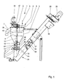
- Fig. 1 shows the device in its entirety.
- the device has a container 1 with a vertical axis 2.
- the container 1 has a wall 3, preferably in a round design, and is arranged vertically aligned with its axis 2.
- the wall 3 of the container 1 is composed of a plurality of cylindrical and / or frustoconical pieces, in particular so that from bottom to top of the cross section is increasingly provided, as shown in FIG. 1.
- the container 1 has in its upper region a charging device 4, for example in the form of a funnel, through which the inorganic material soiled with organic material is introduced into the container 1 according to arrow 5.
- the in the operation of the device adjusting water level 6 is indicated.
- a device 7 for removing organic material and liquid connects to the wall 3 of the container.
- two separate devices may be arranged at different heights, wherein the one device for removing liquid and the other device for the removal of organic material are formed.
- the device for removing organic material is arranged below the device for removing liquid. It connects to a collecting space 8, in which accumulates organic material during operation.
- a supply device 9 for washing water provided, with the aid of washing water according to arrow 10 in the interior of the container. 1 is initiated.
- An inlet port 11 is in continuous communication with a annular conduit 12 in the interior of the container 1, on which the task of washing water he follows.
- a protective collar 13 Above the annular duct 12 is a protective collar 13, the inside of the Wall 3 of the container 1 connects, tapers down funnel-shaped and optionally ends in a cylindrical portion, the lower end below the Ring line 12 is arranged. This is in the gusset between wall 3 and Protective collar 13, a free space 14 created to accommodate the annular Line 12 is used and determined.
- a shaft 15 which via a motor 16 and a Reduction gear 17 is driven in rotation.
- the wave possesses in an area that can start just above the protective collar 13, a screw conveyor 18.
- the Auger 18 may at its lower end via a deflector plate 19 so far be formed closed, so that between the outer diameter of the deflector plate 19 and the inner wall 3 of the container 1, a ring cross-section 20 is formed, from starting up a lifting device 21 on the organic polluted mixture inorganic material and water.
- the lifting device 21 is here designed as a mechanical lifting device. Essential components of this mechanical Lifting device are the shaft 15 and the screw conveyor 18. By the effect the lifting device becomes an upward movement component on the inorganic and organic material exercised.
- the shaft 15 extends with its lower end the protective collar 13 therethrough. It ends below the same and thus forms the Ring cross-section 20 also already in the area of the protective collar 13 before.
- a fluidized layer 22 Approximately between the protective collar 13 to the end of the lifting device 21 and the Auger 18 or slightly beyond forms during operation of the device a fluidized layer 22, so a fluidized bed. Relative to the height or extent of the fluidized layer 22 is outside of the wall 3 of the container 1, a probe 23rd intended.
- the probe 23 serves to detect the density of the fluidized bed. From the measured pressure signals can be a conclusion on the density of the mixture in the fluidized layer 22 and thus take place on the expansion of the fluidized bed.
- These Signals are suitably used to clean the purified inorganic material through the annular cross section in the region of the protective collar 13 passes down and deposits there, with the help of a connected to the lower end of the container 1
- Discharge device 24 carry away obliquely upwards.
- Essential part of the Discharge device 24 for the inorganic material is a screw conveyor with Shaft 25, screw conveyor 26 and housing 27.
- the screw conveyor with the Shaft 25 is clocked via a motor 28 and a downstream transmission 29 driven.
- a chute 30 In the upper part of the housing 27 is a chute 30, with their Help the pumped cleaned inorganic material above the water level 6 is delivered.
- the device is filled with purified inorganic material, ie with sand, whereby the sand settles in the lower region and a sand cone is formed, which ends approximately in the region of the upper end of the protective collar, so that the inner cross section of the protective collar more or less completely filled out.
- the supply device 9 is put into operation for washing water, so that washing water according to arrow 10 passes through the inlet port 11 into the annular conduit 12.
- the annular conduit 12 has upwardly directed outlet openings 31.
- the outlet openings 31 are arranged distributed regularly over the circumference of the annular conduit 12.
- the washing water exits through the outlet openings 31 of the annular lines 12 in the space 14 below the protective collar 13. It can be seen that there is no sand, but rather air and / or water in this free space 14, so that even when the device is at a standstill, the outlet openings can neither be clogged, contaminated nor galvanized.
- the exiting wash water returns according to arrow 32, first its flow direction and then flows under the lower edge of the protective collar 13 as indicated by arrow 33. It takes it cleaned sand with up by flowing through the annulus between protective collar 13 and shaft 15 continues upward, while in the lower area below the protective collar 13 remains a dotted lines indicated by dashed lines sand pile 34 remains.
- a circulating flow is impressed on the fluidized layer 22, which flow is illustrated by the various arrow representations within the fluidized layer 22.
- the grains of sand in the fluidized layer 22 will predominantly move upward in accordance with the arrows 35, while at a larger radius in the region of the wall 3 a direction of movement according to the arrows 36 predominantly occurs downwards ,
- the result is, as shown, an annular roller flow, wherein the flow reversal is illustrated by arrows 37 and 38.
- the flow reversal in the lower region may extend to the annular cross-section at the level of the protective collar 13, while the upper end of the roll flow may also be arranged above the upper end of the screw conveyor 18.
- the shaft 15 of the lifting device 21 can in Area of the collecting space 8, but also in other areas, with stirring arms 39, 40 (Fig. 1), whose task is essentially a solid layer formation of organic material in this area always loosen up and break up, so that the organic material through the device 7 together with the washing water is dissipated.
- stirring arms (not shown), in addition to the effect of the required lifting device 21 the sand grains a more or less horizontal component of movement impress.
- the lifting device 21 is pneumatically formed.
- the shaft 15 is hollow and has a stepped in diameter extension 41. From above, compressed air is introduced through the interior of the shaft 15 and the extension 41 as indicated by arrow 42. Again, the shaft 15 and the extension 41 is driven, so that the compressed air is supplied via a rotary connection. The compressed air exits at the lower end of the extension 41 according to arrow 47 and returns with appropriate washing water supply their flow direction.
- a cylinder wall 43 is rotatably connected, which may have an issued catcher collar 44 at its lower end. The compressed air flows within the cylinder wall 43 according to arrow 45 upwards, so that here also in the operating state on the sand grains an upward movement component according to arrow 35 is issued.
- the cylinder wall 43 is open at the top, so that here according to arrow 37, a reversal of the roll flow within the fluidized layer 22 takes place.
- the cylinder wall 43 may be connected to the shaft 15, so be driven in rotation. It is also possible to hang the cylinder wall 43 stationary on the wall 3. In both cases, an annular or cylindrical superimposed flow of the fluidized layer 22 is impressed here, whereby all those effects are achieved, which also occur with reference to the embodiment of FIG. 2 in a mechanical lifting device 21. Finally, it is also conceivable that mechanical and pneumatic lifting devices 21 can be used in combination with one another.
- the wash water supply is somewhat simplified here.
- On the annular pipe 12 is omitted here, so that the free space 14 below the protective collar 13 for the Distribution of wash water is used.
- the lower edge of the protective collar is here with Provided serrations or recesses 46, on the supplied washing water according to the arrows 33 is guided through the space in the protective collar 13 upwards.
- the Cylinder wall 43 the flow is guided and made uniform, being within the Cylinder wall 43 outweigh the upward flow components, while outside the cylinder wall 43, the downward flow of the recirculation flow takes place.
- the fluidized bed or fluidized air prevails in all two flow cross sections Layer 22 before.
- FIG. 4 shows an embodiment in which the cylinder wall 43 is associated with the screw conveyor 18. It is understood that above the screw conveyor 18, a shaft 15 is provided (not shown), which continues in the lower region of the screw conveyor 18, while a large portion of the height of the screw conveyor 18 is formed wave-less.
- the cylinder wall 43 is connected to the screw conveyor 18 to a co-rotating unit, which is designed to be open at the top and bottom.
- an upward movement component according to the arrows 35, 45 prevails within the cylinder wall 43.
- the annular duct 12 is arranged circumferentially outside the wall 3, while the outlet openings 31 pass through the wall 3.
- the shaft 15 may also be provided in a departure from the diagrammatic representation of FIG. 4, as shown in FIG. 2.
- the fluidized layer 22 is formed by the interaction of the ascending wash water and the lifting device 21 ensured. This results not only the fluidized layer 22, but the impressed recirculation flow.
Landscapes
- Chemical & Material Sciences (AREA)
- Chemical Kinetics & Catalysis (AREA)
- Separation Of Solids By Using Liquids Or Pneumatic Power (AREA)
- Processing Of Solid Wastes (AREA)
- Devices And Processes Conducted In The Presence Of Fluids And Solid Particles (AREA)
- Organic Low-Molecular-Weight Compounds And Preparation Thereof (AREA)
- Cleaning By Liquid Or Steam (AREA)
Priority Applications (1)
| Application Number | Priority Date | Filing Date | Title |
|---|---|---|---|
| PL04021875T PL1516672T3 (pl) | 2003-09-22 | 2004-09-15 | Sposób i urządzenie do oddzielania materiału organicznego od materiału nieorganicznego |
Applications Claiming Priority (2)
| Application Number | Priority Date | Filing Date | Title |
|---|---|---|---|
| DE10343788 | 2003-09-22 | ||
| DE10343788A DE10343788A1 (de) | 2003-09-22 | 2003-09-22 | Vorrichtung zum Abtrennen von organischem Material von anorganischem Material |
Publications (2)
| Publication Number | Publication Date |
|---|---|
| EP1516672A1 true EP1516672A1 (fr) | 2005-03-23 |
| EP1516672B1 EP1516672B1 (fr) | 2011-04-20 |
Family
ID=34177879
Family Applications (1)
| Application Number | Title | Priority Date | Filing Date |
|---|---|---|---|
| EP04021875A Expired - Lifetime EP1516672B1 (fr) | 2003-09-22 | 2004-09-15 | Procédé et dispositif pour la séparation de matière organique de matière inorganique |
Country Status (8)
| Country | Link |
|---|---|
| US (1) | US7318527B2 (fr) |
| EP (1) | EP1516672B1 (fr) |
| JP (1) | JP2005095890A (fr) |
| CN (1) | CN1600439A (fr) |
| AT (1) | ATE506123T1 (fr) |
| DE (2) | DE10343788A1 (fr) |
| ES (1) | ES2364879T3 (fr) |
| PL (1) | PL1516672T3 (fr) |
Families Citing this family (14)
| Publication number | Priority date | Publication date | Assignee | Title |
|---|---|---|---|---|
| EP2001596A4 (fr) * | 2006-03-20 | 2014-02-19 | Parkson Corp | Méthode et appareil de nettoyage de sable |
| US7954642B2 (en) * | 2008-09-26 | 2011-06-07 | U Chicago Argonne, Llc | Process and apparatus for separating solid mixtures |
| CN201389491Y (zh) * | 2009-04-07 | 2010-01-27 | 陈文宏 | 导砂洗砂机 |
| CN101912758B (zh) * | 2010-08-03 | 2013-11-06 | 沈安平 | 一种v型反应釜 |
| CN102039216A (zh) * | 2010-09-01 | 2011-05-04 | 王银河 | 有机物垃圾搅拌除渣机 |
| US8730243B2 (en) | 2011-01-19 | 2014-05-20 | General Electric Company | Systems, methods, and user interfaces for displaying waveform information |
| CN102205262B (zh) * | 2011-05-17 | 2014-02-26 | 中国科学院过程工程研究所 | 液固干扰流化床分选机、其分选方法及应用 |
| WO2013168155A1 (fr) | 2012-05-07 | 2013-11-14 | Aqwise - Wise Water Technologies | Elimination de résidus accumulés sur des supports mis en oeuvre dans un système de traitement de l'eau |
| DE102015112254A1 (de) * | 2015-07-28 | 2017-02-02 | Bta International Gmbh | Hydrodynamische Schwerstoffabtrennung einer Aufschlämmung |
| EA201890533A1 (ru) * | 2015-08-28 | 2018-09-28 | Хантер Просесс Текнолоджис Пти Лимитед | Система, способ и устройство для пенной флотации |
| GB2556038A (en) * | 2016-11-10 | 2018-05-23 | Henry Coulton Richard | Separator apparatus and method |
| CN117123558A (zh) * | 2023-09-15 | 2023-11-28 | 安徽富春色纺有限公司 | 一种砂粒清洗装置及其清洗方法 |
| CN117963574B (zh) * | 2024-03-29 | 2024-07-23 | 巴中碳原子新材料科技有限公司 | 一种具有负压功能的卸料器 |
| EP4628183A1 (fr) | 2024-04-02 | 2025-10-08 | Stjernholm A/S | Installation de séparation de sable-liquide, utilisation de cette installation et procédé d'utilisation de cette installation |
Citations (10)
| Publication number | Priority date | Publication date | Assignee | Title |
|---|---|---|---|---|
| US630309A (en) * | 1897-12-24 | 1899-08-08 | Albert Aeberg | Apparatus for cleaning paper-pulp. |
| US1277145A (en) * | 1917-10-30 | 1918-08-27 | Leroy E Sowers | Separator for separating manganese dioxid from ores containing the same. |
| EP0469360A2 (fr) * | 1990-08-02 | 1992-02-05 | OFFICINE MECCANICHE FERRERO S.p.A. | Procédé et dispositif pour la séparation humide de mélanges hétérogènes contenant des solides de densités différentes |
| US5167375A (en) * | 1988-04-04 | 1992-12-01 | Datta Rabinder S | Apparatus for mineral matter separation |
| DE4415647C2 (de) | 1994-05-04 | 1996-10-02 | Huber Hans Gmbh Maschinen Und | Vorrichtung zum Abtrennen von mit organischem Material verschmutztem anorganischem Material aus einer Flüssigkeit |
| DE29614456U1 (de) * | 1996-08-21 | 1996-11-14 | Feierabend, Andreas, 45326 Essen | Vorrichtung zum Reinigen und Abtrennen von Sand aus einem Sand/Flüssigkeitsgemisch, insbesondere Sand/Wassergemisch |
| EP0713418B1 (fr) | 1993-08-13 | 1998-10-21 | Noggerath Holding GmbH & Co. KG | Procede et dispositif permettant d'extraire du sable contenu dans des eaux usees chargees en sable et en substances organiques |
| DE19805451A1 (de) * | 1998-02-11 | 1999-08-19 | Bormet Maschinenbau Gmbh | Kehrichtwascher |
| DE19844006A1 (de) | 1998-09-25 | 2000-04-06 | Strate Technologie Fuer Abwass | Sandwäsche |
| EP1002563A1 (fr) * | 1998-11-17 | 2000-05-24 | FirstEnergy Ventures | Procédé et dispositif pour separer des particules de décantation rapide de particules de décantation lente |
Family Cites Families (4)
| Publication number | Priority date | Publication date | Assignee | Title |
|---|---|---|---|---|
| US964261A (en) * | 1910-03-14 | 1910-07-12 | Frank G Janney | Ore-classifier. |
| US1035145A (en) * | 1912-04-05 | 1912-08-13 | Lewis L Beeken | Hydraulic classifier. |
| US2519781A (en) * | 1946-09-30 | 1950-08-22 | Alexander B Morris | Apparatus for cleaning and/or grading for size, sand, or other similar substances |
| US4124497A (en) * | 1976-07-02 | 1978-11-07 | Hulegard Trueman L | Apparatus for separating mineral and the like from earth and the like |
-
2003
- 2003-09-22 DE DE10343788A patent/DE10343788A1/de not_active Withdrawn
-
2004
- 2004-09-15 AT AT04021875T patent/ATE506123T1/de active
- 2004-09-15 EP EP04021875A patent/EP1516672B1/fr not_active Expired - Lifetime
- 2004-09-15 PL PL04021875T patent/PL1516672T3/pl unknown
- 2004-09-15 DE DE502004012411T patent/DE502004012411D1/de not_active Expired - Lifetime
- 2004-09-15 ES ES04021875T patent/ES2364879T3/es not_active Expired - Lifetime
- 2004-09-21 JP JP2004273478A patent/JP2005095890A/ja not_active Withdrawn
- 2004-09-21 US US10/946,417 patent/US7318527B2/en not_active Expired - Lifetime
- 2004-09-22 CN CNA2004100824775A patent/CN1600439A/zh active Pending
Patent Citations (11)
| Publication number | Priority date | Publication date | Assignee | Title |
|---|---|---|---|---|
| US630309A (en) * | 1897-12-24 | 1899-08-08 | Albert Aeberg | Apparatus for cleaning paper-pulp. |
| US1277145A (en) * | 1917-10-30 | 1918-08-27 | Leroy E Sowers | Separator for separating manganese dioxid from ores containing the same. |
| US5167375A (en) * | 1988-04-04 | 1992-12-01 | Datta Rabinder S | Apparatus for mineral matter separation |
| EP0469360A2 (fr) * | 1990-08-02 | 1992-02-05 | OFFICINE MECCANICHE FERRERO S.p.A. | Procédé et dispositif pour la séparation humide de mélanges hétérogènes contenant des solides de densités différentes |
| EP0713418B1 (fr) | 1993-08-13 | 1998-10-21 | Noggerath Holding GmbH & Co. KG | Procede et dispositif permettant d'extraire du sable contenu dans des eaux usees chargees en sable et en substances organiques |
| DE4415647C2 (de) | 1994-05-04 | 1996-10-02 | Huber Hans Gmbh Maschinen Und | Vorrichtung zum Abtrennen von mit organischem Material verschmutztem anorganischem Material aus einer Flüssigkeit |
| EP0707520B1 (fr) | 1994-05-04 | 1999-04-21 | Hans Huber GmbH Maschinen- und Anlagenbau | Dispositif permettant de separer d'un liquide un materiau inorganique pollue par un materiau organique |
| DE29614456U1 (de) * | 1996-08-21 | 1996-11-14 | Feierabend, Andreas, 45326 Essen | Vorrichtung zum Reinigen und Abtrennen von Sand aus einem Sand/Flüssigkeitsgemisch, insbesondere Sand/Wassergemisch |
| DE19805451A1 (de) * | 1998-02-11 | 1999-08-19 | Bormet Maschinenbau Gmbh | Kehrichtwascher |
| DE19844006A1 (de) | 1998-09-25 | 2000-04-06 | Strate Technologie Fuer Abwass | Sandwäsche |
| EP1002563A1 (fr) * | 1998-11-17 | 2000-05-24 | FirstEnergy Ventures | Procédé et dispositif pour separer des particules de décantation rapide de particules de décantation lente |
Also Published As
| Publication number | Publication date |
|---|---|
| US7318527B2 (en) | 2008-01-15 |
| EP1516672B1 (fr) | 2011-04-20 |
| DE10343788A1 (de) | 2005-04-28 |
| CN1600439A (zh) | 2005-03-30 |
| PL1516672T3 (pl) | 2011-09-30 |
| ES2364879T3 (es) | 2011-09-15 |
| ATE506123T1 (de) | 2011-05-15 |
| US20050061715A1 (en) | 2005-03-24 |
| DE502004012411D1 (de) | 2011-06-01 |
| JP2005095890A (ja) | 2005-04-14 |
Similar Documents
| Publication | Publication Date | Title |
|---|---|---|
| DE4415647C2 (de) | Vorrichtung zum Abtrennen von mit organischem Material verschmutztem anorganischem Material aus einer Flüssigkeit | |
| EP1516672B1 (fr) | Procédé et dispositif pour la séparation de matière organique de matière inorganique | |
| EP0592508B1 (fr) | Procede et dispositif pour l'amelioration du traitement de matieres solides contenues dans les eaux usees, de sable, de dechets ou similaires | |
| EP2012901A1 (fr) | Procede et dispositif de separation de solides grossiers d'un fluide visqueux | |
| DE2042353C3 (de) | Vorrichtung zum Filtrieren von Flüssigkeiten | |
| DE4212097C2 (fr) | ||
| EP0630674B1 (fr) | Dispositif pour la séparation des râtelures d'un courant liquide pollué dans une ligole, spécialement pour installations d'épuration | |
| EP1210987B1 (fr) | Dispositif pour obtenir des fractions grosses et fines à partir d' un mélange de sable | |
| DE10200599B4 (de) | Vorrichtung zum Abscheiden von organischem und anorganischem Material aus einer Flüssigkeit | |
| EP0927579A2 (fr) | Procédé et dispositif pour extraire des solides d' un mélange solide- liquide | |
| EP1137469B1 (fr) | Dispositif de separation d'eau usee | |
| EP0811428A2 (fr) | Dispositif pour séparer des matières composites en suspension dans un liquide | |
| DE19924164C2 (de) | Verfahren und Vorrichtung zur Separation von aus organischem und anorganischem Material zusammengesetzten Feststoffen aus einer mit Feststoffen vermischten Flüssigkeit und zur Abtrennung des anorganischen Materials aus dem Gemisch von organischen und anorganischem Material | |
| DE2444241C3 (de) | Verfahren und Vorrichtung zum Abtrennen der anorganischen Feststoffe von den organischen aus Abwässern | |
| DE4410969C1 (de) | Vorrichtung zum Trennen von leichtlöslichen Stoffen, Schwebestoffen und schwerlöslichen Stoffen aus einem Feststoff- oder Flüssigkeit-Feststoffgemisch | |
| EP1079933B1 (fr) | Separation de matieres solides composees de matiere organique et de matiere inorganique | |
| WO1995019212A1 (fr) | Dispositif de nettoyage de solides contenus dans des eaux residuaires | |
| EP1134323A2 (fr) | Trappe de sable | |
| DE9209026U1 (de) | Vorrichtung zur Verbesserung der Aufbereitung von Abwasser-Feststoffen, Sand, Müll o.dgl. | |
| WO2021121632A1 (fr) | Lavage de produits en vrac | |
| EP0732458B1 (fr) | Dispositif pour l'élimination des particules solides d'une masse solide/liquide | |
| WO2017174500A1 (fr) | Procédé et installation servant au traitement de cendres provenant d'un incinérateur de déchets | |
| EP4667105A1 (fr) | Dispositif et procédé de lavage d'une masse d'excavation pré-fine | |
| DE20311155U1 (de) | Anlage zum Trennen und Aufbereiten eines Gemischs aus Abwasser und Sand | |
| DE10361786A1 (de) | Vorrichtung zum Trennen von mit organischem Material verschmutzten anorganischem Material aus einer Schmutzflüssigkeit |
Legal Events
| Date | Code | Title | Description |
|---|---|---|---|
| PUAI | Public reference made under article 153(3) epc to a published international application that has entered the european phase |
Free format text: ORIGINAL CODE: 0009012 |
|
| AK | Designated contracting states |
Kind code of ref document: A1 Designated state(s): AT BE BG CH CY CZ DE DK EE ES FI FR GB GR HU IE IT LI LU MC NL PL PT RO SE SI SK TR |
|
| AX | Request for extension of the european patent |
Extension state: AL HR LT LV MK |
|
| 17P | Request for examination filed |
Effective date: 20050222 |
|
| AKX | Designation fees paid |
Designated state(s): AT BE BG CH CY CZ DE DK EE ES FI FR GB GR HU IE IT LI LU MC NL PL PT RO SE SI SK TR |
|
| 17Q | First examination report despatched |
Effective date: 20061227 |
|
| RAP1 | Party data changed (applicant data changed or rights of an application transferred) |
Owner name: HUBER SE |
|
| GRAP | Despatch of communication of intention to grant a patent |
Free format text: ORIGINAL CODE: EPIDOSNIGR1 |
|
| RTI1 | Title (correction) |
Free format text: METHOD AND APPARATUS FOR SEPARATING OF ORGANIC FROM INORGANIC MATERIAL |
|
| GRAS | Grant fee paid |
Free format text: ORIGINAL CODE: EPIDOSNIGR3 |
|
| GRAA | (expected) grant |
Free format text: ORIGINAL CODE: 0009210 |
|
| AK | Designated contracting states |
Kind code of ref document: B1 Designated state(s): AT BE BG CH CY CZ DE DK EE ES FI FR GB GR HU IE IT LI LU MC NL PL PT RO SE SI SK TR |
|
| REG | Reference to a national code |
Ref country code: GB Ref legal event code: FG4D Free format text: NOT ENGLISH |
|
| REG | Reference to a national code |
Ref country code: CH Ref legal event code: EP |
|
| REG | Reference to a national code |
Ref country code: IE Ref legal event code: FG4D Free format text: LANGUAGE OF EP DOCUMENT: GERMAN |
|
| REF | Corresponds to: |
Ref document number: 502004012411 Country of ref document: DE Date of ref document: 20110601 Kind code of ref document: P |
|
| REG | Reference to a national code |
Ref country code: DE Ref legal event code: R096 Ref document number: 502004012411 Country of ref document: DE Effective date: 20110601 |
|
| REG | Reference to a national code |
Ref country code: SE Ref legal event code: TRGR |
|
| REG | Reference to a national code |
Ref country code: NL Ref legal event code: VDEP Effective date: 20110420 |
|
| REG | Reference to a national code |
Ref country code: ES Ref legal event code: FG2A Ref document number: 2364879 Country of ref document: ES Kind code of ref document: T3 Effective date: 20110915 |
|
| REG | Reference to a national code |
Ref country code: PL Ref legal event code: T3 |
|
| PG25 | Lapsed in a contracting state [announced via postgrant information from national office to epo] |
Ref country code: PT Free format text: LAPSE BECAUSE OF FAILURE TO SUBMIT A TRANSLATION OF THE DESCRIPTION OR TO PAY THE FEE WITHIN THE PRESCRIBED TIME-LIMIT Effective date: 20110822 |
|
| REG | Reference to a national code |
Ref country code: IE Ref legal event code: FD4D |
|
| PG25 | Lapsed in a contracting state [announced via postgrant information from national office to epo] |
Ref country code: FI Free format text: LAPSE BECAUSE OF FAILURE TO SUBMIT A TRANSLATION OF THE DESCRIPTION OR TO PAY THE FEE WITHIN THE PRESCRIBED TIME-LIMIT Effective date: 20110420 Ref country code: GR Free format text: LAPSE BECAUSE OF FAILURE TO SUBMIT A TRANSLATION OF THE DESCRIPTION OR TO PAY THE FEE WITHIN THE PRESCRIBED TIME-LIMIT Effective date: 20110721 Ref country code: SI Free format text: LAPSE BECAUSE OF FAILURE TO SUBMIT A TRANSLATION OF THE DESCRIPTION OR TO PAY THE FEE WITHIN THE PRESCRIBED TIME-LIMIT Effective date: 20110420 Ref country code: CY Free format text: LAPSE BECAUSE OF FAILURE TO SUBMIT A TRANSLATION OF THE DESCRIPTION OR TO PAY THE FEE WITHIN THE PRESCRIBED TIME-LIMIT Effective date: 20110420 |
|
| PG25 | Lapsed in a contracting state [announced via postgrant information from national office to epo] |
Ref country code: NL Free format text: LAPSE BECAUSE OF FAILURE TO SUBMIT A TRANSLATION OF THE DESCRIPTION OR TO PAY THE FEE WITHIN THE PRESCRIBED TIME-LIMIT Effective date: 20110420 |
|
| PG25 | Lapsed in a contracting state [announced via postgrant information from national office to epo] |
Ref country code: CZ Free format text: LAPSE BECAUSE OF FAILURE TO SUBMIT A TRANSLATION OF THE DESCRIPTION OR TO PAY THE FEE WITHIN THE PRESCRIBED TIME-LIMIT Effective date: 20110420 Ref country code: IE Free format text: LAPSE BECAUSE OF FAILURE TO SUBMIT A TRANSLATION OF THE DESCRIPTION OR TO PAY THE FEE WITHIN THE PRESCRIBED TIME-LIMIT Effective date: 20110420 Ref country code: EE Free format text: LAPSE BECAUSE OF FAILURE TO SUBMIT A TRANSLATION OF THE DESCRIPTION OR TO PAY THE FEE WITHIN THE PRESCRIBED TIME-LIMIT Effective date: 20110420 |
|
| PLBE | No opposition filed within time limit |
Free format text: ORIGINAL CODE: 0009261 |
|
| STAA | Information on the status of an ep patent application or granted ep patent |
Free format text: STATUS: NO OPPOSITION FILED WITHIN TIME LIMIT |
|
| PG25 | Lapsed in a contracting state [announced via postgrant information from national office to epo] |
Ref country code: RO Free format text: LAPSE BECAUSE OF FAILURE TO SUBMIT A TRANSLATION OF THE DESCRIPTION OR TO PAY THE FEE WITHIN THE PRESCRIBED TIME-LIMIT Effective date: 20110420 Ref country code: DK Free format text: LAPSE BECAUSE OF FAILURE TO SUBMIT A TRANSLATION OF THE DESCRIPTION OR TO PAY THE FEE WITHIN THE PRESCRIBED TIME-LIMIT Effective date: 20110420 Ref country code: SK Free format text: LAPSE BECAUSE OF FAILURE TO SUBMIT A TRANSLATION OF THE DESCRIPTION OR TO PAY THE FEE WITHIN THE PRESCRIBED TIME-LIMIT Effective date: 20110420 |
|
| 26N | No opposition filed |
Effective date: 20120123 |
|
| BERE | Be: lapsed |
Owner name: HUBER SE Effective date: 20110930 |
|
| PG25 | Lapsed in a contracting state [announced via postgrant information from national office to epo] |
Ref country code: MC Free format text: LAPSE BECAUSE OF NON-PAYMENT OF DUE FEES Effective date: 20110930 |
|
| REG | Reference to a national code |
Ref country code: DE Ref legal event code: R097 Ref document number: 502004012411 Country of ref document: DE Effective date: 20120123 |
|
| PG25 | Lapsed in a contracting state [announced via postgrant information from national office to epo] |
Ref country code: IT Free format text: LAPSE BECAUSE OF FAILURE TO SUBMIT A TRANSLATION OF THE DESCRIPTION OR TO PAY THE FEE WITHIN THE PRESCRIBED TIME-LIMIT Effective date: 20110420 |
|
| PG25 | Lapsed in a contracting state [announced via postgrant information from national office to epo] |
Ref country code: BE Free format text: LAPSE BECAUSE OF NON-PAYMENT OF DUE FEES Effective date: 20110930 |
|
| PG25 | Lapsed in a contracting state [announced via postgrant information from national office to epo] |
Ref country code: LU Free format text: LAPSE BECAUSE OF NON-PAYMENT OF DUE FEES Effective date: 20110915 |
|
| PG25 | Lapsed in a contracting state [announced via postgrant information from national office to epo] |
Ref country code: BG Free format text: LAPSE BECAUSE OF FAILURE TO SUBMIT A TRANSLATION OF THE DESCRIPTION OR TO PAY THE FEE WITHIN THE PRESCRIBED TIME-LIMIT Effective date: 20110720 |
|
| PG25 | Lapsed in a contracting state [announced via postgrant information from national office to epo] |
Ref country code: TR Free format text: LAPSE BECAUSE OF FAILURE TO SUBMIT A TRANSLATION OF THE DESCRIPTION OR TO PAY THE FEE WITHIN THE PRESCRIBED TIME-LIMIT Effective date: 20110420 |
|
| PG25 | Lapsed in a contracting state [announced via postgrant information from national office to epo] |
Ref country code: HU Free format text: LAPSE BECAUSE OF FAILURE TO SUBMIT A TRANSLATION OF THE DESCRIPTION OR TO PAY THE FEE WITHIN THE PRESCRIBED TIME-LIMIT Effective date: 20110420 |
|
| PGFP | Annual fee paid to national office [announced via postgrant information from national office to epo] |
Ref country code: ES Payment date: 20150924 Year of fee payment: 12 |
|
| REG | Reference to a national code |
Ref country code: FR Ref legal event code: PLFP Year of fee payment: 13 |
|
| REG | Reference to a national code |
Ref country code: FR Ref legal event code: PLFP Year of fee payment: 14 |
|
| PGFP | Annual fee paid to national office [announced via postgrant information from national office to epo] |
Ref country code: CH Payment date: 20170920 Year of fee payment: 14 |
|
| PGFP | Annual fee paid to national office [announced via postgrant information from national office to epo] |
Ref country code: AT Payment date: 20170921 Year of fee payment: 14 Ref country code: SE Payment date: 20170921 Year of fee payment: 14 |
|
| PG25 | Lapsed in a contracting state [announced via postgrant information from national office to epo] |
Ref country code: ES Free format text: LAPSE BECAUSE OF NON-PAYMENT OF DUE FEES Effective date: 20160916 |
|
| REG | Reference to a national code |
Ref country code: FR Ref legal event code: PLFP Year of fee payment: 15 |
|
| REG | Reference to a national code |
Ref country code: ES Ref legal event code: FD2A Effective date: 20181128 |
|
| REG | Reference to a national code |
Ref country code: SE Ref legal event code: EUG Ref country code: CH Ref legal event code: PL |
|
| REG | Reference to a national code |
Ref country code: AT Ref legal event code: MM01 Ref document number: 506123 Country of ref document: AT Kind code of ref document: T Effective date: 20180915 |
|
| PG25 | Lapsed in a contracting state [announced via postgrant information from national office to epo] |
Ref country code: SE Free format text: LAPSE BECAUSE OF NON-PAYMENT OF DUE FEES Effective date: 20180916 |
|
| PG25 | Lapsed in a contracting state [announced via postgrant information from national office to epo] |
Ref country code: CH Free format text: LAPSE BECAUSE OF NON-PAYMENT OF DUE FEES Effective date: 20180930 Ref country code: LI Free format text: LAPSE BECAUSE OF NON-PAYMENT OF DUE FEES Effective date: 20180930 |
|
| PG25 | Lapsed in a contracting state [announced via postgrant information from national office to epo] |
Ref country code: AT Free format text: LAPSE BECAUSE OF NON-PAYMENT OF DUE FEES Effective date: 20180915 |
|
| PGFP | Annual fee paid to national office [announced via postgrant information from national office to epo] |
Ref country code: GB Payment date: 20220922 Year of fee payment: 19 |
|
| PGFP | Annual fee paid to national office [announced via postgrant information from national office to epo] |
Ref country code: FR Payment date: 20220924 Year of fee payment: 19 |
|
| PGFP | Annual fee paid to national office [announced via postgrant information from national office to epo] |
Ref country code: PL Payment date: 20230828 Year of fee payment: 20 Ref country code: DE Payment date: 20230915 Year of fee payment: 20 |
|
| GBPC | Gb: european patent ceased through non-payment of renewal fee |
Effective date: 20230915 |
|
| PG25 | Lapsed in a contracting state [announced via postgrant information from national office to epo] |
Ref country code: GB Free format text: LAPSE BECAUSE OF NON-PAYMENT OF DUE FEES Effective date: 20230915 |
|
| PG25 | Lapsed in a contracting state [announced via postgrant information from national office to epo] |
Ref country code: GB Free format text: LAPSE BECAUSE OF NON-PAYMENT OF DUE FEES Effective date: 20230915 Ref country code: FR Free format text: LAPSE BECAUSE OF NON-PAYMENT OF DUE FEES Effective date: 20230930 |
|
| REG | Reference to a national code |
Ref country code: DE Ref legal event code: R071 Ref document number: 502004012411 Country of ref document: DE |