EP0707760B1 - Dispositif avec antenne directionelle de radiocommunication sans fil - Google Patents
Dispositif avec antenne directionelle de radiocommunication sans fil Download PDFInfo
- Publication number
- EP0707760B1 EP0707760B1 EP94924418A EP94924418A EP0707760B1 EP 0707760 B1 EP0707760 B1 EP 0707760B1 EP 94924418 A EP94924418 A EP 94924418A EP 94924418 A EP94924418 A EP 94924418A EP 0707760 B1 EP0707760 B1 EP 0707760B1
- Authority
- EP
- European Patent Office
- Prior art keywords
- conductor
- antenna
- housing
- conducting
- information exchange
- Prior art date
- Legal status (The legal status is an assumption and is not a legal conclusion. Google has not performed a legal analysis and makes no representation as to the accuracy of the status listed.)
- Expired - Lifetime
Links
Images




Classifications
-
- H—ELECTRICITY
- H01—ELECTRIC ELEMENTS
- H01Q—ANTENNAS, i.e. RADIO AERIALS
- H01Q1/00—Details of, or arrangements associated with, antennas
- H01Q1/12—Supports; Mounting means
- H01Q1/22—Supports; Mounting means by structural association with other equipment or articles
- H01Q1/24—Supports; Mounting means by structural association with other equipment or articles with receiving set
- H01Q1/241—Supports; Mounting means by structural association with other equipment or articles with receiving set used in mobile communications, e.g. GSM
- H01Q1/242—Supports; Mounting means by structural association with other equipment or articles with receiving set used in mobile communications, e.g. GSM specially adapted for hand-held use
- H01Q1/243—Supports; Mounting means by structural association with other equipment or articles with receiving set used in mobile communications, e.g. GSM specially adapted for hand-held use with built-in antennas
-
- H—ELECTRICITY
- H01—ELECTRIC ELEMENTS
- H01Q—ANTENNAS, i.e. RADIO AERIALS
- H01Q1/00—Details of, or arrangements associated with, antennas
- H01Q1/12—Supports; Mounting means
- H01Q1/22—Supports; Mounting means by structural association with other equipment or articles
- H01Q1/24—Supports; Mounting means by structural association with other equipment or articles with receiving set
- H01Q1/241—Supports; Mounting means by structural association with other equipment or articles with receiving set used in mobile communications, e.g. GSM
- H01Q1/242—Supports; Mounting means by structural association with other equipment or articles with receiving set used in mobile communications, e.g. GSM specially adapted for hand-held use
- H01Q1/245—Supports; Mounting means by structural association with other equipment or articles with receiving set used in mobile communications, e.g. GSM specially adapted for hand-held use with means for shaping the antenna pattern, e.g. in order to protect user against rf exposure
-
- H—ELECTRICITY
- H04—ELECTRIC COMMUNICATION TECHNIQUE
- H04B—TRANSMISSION
- H04B1/00—Details of transmission systems, not covered by a single one of groups H04B3/00 - H04B13/00; Details of transmission systems not characterised by the medium used for transmission
- H04B1/38—Transceivers, i.e. devices in which transmitter and receiver form a structural unit and in which at least one part is used for functions of transmitting and receiving
- H04B1/3827—Portable transceivers
- H04B1/3833—Hand-held transceivers
-
- H—ELECTRICITY
- H04—ELECTRIC COMMUNICATION TECHNIQUE
- H04B—TRANSMISSION
- H04B1/00—Details of transmission systems, not covered by a single one of groups H04B3/00 - H04B13/00; Details of transmission systems not characterised by the medium used for transmission
- H04B1/38—Transceivers, i.e. devices in which transmitter and receiver form a structural unit and in which at least one part is used for functions of transmitting and receiving
- H04B1/3827—Portable transceivers
- H04B1/3833—Hand-held transceivers
- H04B1/3838—Arrangements for reducing RF exposure to the user, e.g. by changing the shape of the transceiver while in use
Definitions
- the basic objective of the invention is to provide a device for cordless radio communication, wherein steps are taken aimed at reducing the influence of the body of a user, or a part of the body, on the electromagnetic energy effectively transmitted and/or received by the antenna means.
- the invention is based on the insight that it is of no practical value to design the antenna means such that during use they generate electromagnetic energy in a direction shielded by the body of the user or a part thereof and/or are sensitive to reception of radio-frequent radiation from this direction.
- the invention involves providing a device for cordless radio communication provided with antenna means having an asymmetrical directional pattern which has an attenuation in the direction of the side from which the means for information exchange are accessible to the user.
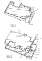
- Fig. 4 shows the shielding 23 with the plate 26 from the open side thereof. It is apparent that the peripheral form of shielding 23 corresponds with the form of the contour 22.
- the former is provided with pins 25 which correspond in location with holes 24 in the contour 22.
- the pins can be joined to the contour by soldering.
- Other connecting techniques are of course also possible, such as for instance the use of pins 25 with retention action in combination with plated-through holes 24.
Landscapes
- Engineering & Computer Science (AREA)
- Computer Networks & Wireless Communication (AREA)
- Signal Processing (AREA)
- Support Of Aerials (AREA)
- Telephone Set Structure (AREA)
- Transceivers (AREA)
- Mobile Radio Communication Systems (AREA)
- Details Of Aerials (AREA)
Claims (11)
- Dispositif (1) de radiocommunication sans cordon pourvu d'un boítier (2), de moyens d'échange d'informations (4-9) logés dans le boítier (2) et accessibles à un utilisateur sur un côté (3) du boítier (2), d'un moyen de traitement de signal (11) couplé aux moyens d'échange d'informations (4-9) et d'un moyen de radiotransmission (12) couplé au moyen de traitement de signal (11) et pourvu d'un moyen d'antenne, dans lequel le moyen d'antenne comprend:caractérisé en ce queune surface de terre électriquement conductrice (16; 26; 29) connectée à un moyen de masse électrique commun (20) du dispositif (1);au moins un élément électriquement conducteur (14; 18; 30; 31; 32; 35) pour recevoir et/ou transmettre des signaux radio, l'élément comprenant au moins un élément (14) s'étendant sensiblement transversalement par rapport à la surface conductrice (16; 26; 29) et étant connecté au moyen de radiotransmission (12),ledit élément conducteur (14) s'étend dans un plan qui est sensiblement parallèle audit côté (3) du boítier (2) à partir duquel les moyens d'échange d'informations (4-9) sont accessibles, et dans lequelladite surface électriquement conductrice (16; 26; 29) s'étend à partir dudit plan (21) uniquement en direction dudit côté (3) du boítier (2) à partir duquel les moyens d'échange d'informations sont accessibles.
- Dispositif (1) selon la revendication 1, dans lequel la surface conductrice (26) est de forme sensiblement plate (27, 28), dont une partie (27) assume une position inclinée par rapport audit côté (3) du boítier (2).
- Dispositif (1) selon la revendication 1 ou 2, dans lequel la surface conductrice (26, 29) fait partie d'un blindage électriquement conducteur entourant totalement ou partiellement au moins le moyen de radiotransmission (12).
- Dispositif (1) selon la revendication 1, dans lequel la surface conductrice (16) est formée par des boítiers et/ou moyens de protection électriquement conducteurs de composants distincts montés dans le dispositif (1) et connectés au moyen de masse électrique (20) de celui-ci.
- Dispositif (1) selon la revendication 1, 2, 3 ou 4, dans lequel l'élément conducteur comprend un premier conducteur électrique (14) ayant une extrémité (15) connectée au moyen de masse électrique (20) du dispositif (1) et une autre extrémité (17) connectée à un deuxième conducteur électrique (18; 30; 31; 32; 35), lequel second conducteur (18; 30; 31; 32; 35) est de forme allongée et s'étend sensiblement transversalement par rapport au premier conducteur (14), dans lequel le premier conducteur (14) est pourvu, dans la région située entre lesdites extrémités (15, 17), d'une borne (19) en vue d'une connexion au moyen de radiotransmission (11) du dispositif (1).
- Dispositif (1) selon la revendication 5, dans lequel le deuxième conducteur (31; 32) a au moins une extrémité (33; 34) formant un angle avec sa direction dans le sens de la longueur.
- Dispositif (1) selon la revendication 5, dans lequel le deuxième conducteur (35) forme un contour totalement ou partiellement fermé.
- Dispositif (1) selon l'une quelconque des revendications précédentes, dans lequel l'élément conducteur (14; 18; 30; 31; 32; 35) fait partie d'une carte à circuit imprimé (21).
- Dispositif (1) selon la revendication 8, dans lequel l'élément conducteur (14; 18; 30; 31; 35) est monté près d'un bord de la carte à circuit imprimé (21).
- Dispositif (1) selon l'une quelconque des revendications précédentes, dans lequel la surface conductrice (26; 29) et l'élément conducteur (14; 18; 30; 31; 32; 35) sont logés de façon fixe dans le boítier (2) renfermant le dispositif (1).
- Dispositif (1) selon l'une quelconque des revendications précédentes, dans lequel les moyens d'échange d'informations (4-9) comprennent des moyens pour capter (4) et reproduire (5) des signaux audio, lesquels moyens (4; 5) sont accessibles à un utilisateur sur ledit côté (3) du boítier (2) à la manière d'un combiné téléphonique (1).
Priority Applications (1)
| Application Number | Priority Date | Filing Date | Title |
|---|---|---|---|
| EP94924418A EP0707760B1 (fr) | 1993-07-09 | 1994-07-11 | Dispositif avec antenne directionelle de radiocommunication sans fil |
Applications Claiming Priority (6)
| Application Number | Priority Date | Filing Date | Title |
|---|---|---|---|
| EP93202040 | 1993-07-09 | ||
| EP93202040 | 1993-07-09 | ||
| NL9302192 | 1993-12-15 | ||
| NL9302192A NL9302192A (nl) | 1993-07-09 | 1993-12-15 | Draadloze telefoon. |
| EP94924418A EP0707760B1 (fr) | 1993-07-09 | 1994-07-11 | Dispositif avec antenne directionelle de radiocommunication sans fil |
| PCT/NL1994/000158 WO1995002284A1 (fr) | 1993-07-09 | 1994-07-11 | Dispositif et antenne de radiocommunication sans fil |
Publications (2)
| Publication Number | Publication Date |
|---|---|
| EP0707760A1 EP0707760A1 (fr) | 1996-04-24 |
| EP0707760B1 true EP0707760B1 (fr) | 1998-11-25 |
Family
ID=26133910
Family Applications (1)
| Application Number | Title | Priority Date | Filing Date |
|---|---|---|---|
| EP94924418A Expired - Lifetime EP0707760B1 (fr) | 1993-07-09 | 1994-07-11 | Dispositif avec antenne directionelle de radiocommunication sans fil |
Country Status (10)
| Country | Link |
|---|---|
| US (1) | US5802458A (fr) |
| EP (1) | EP0707760B1 (fr) |
| JP (1) | JPH09500246A (fr) |
| AU (1) | AU686214B2 (fr) |
| CA (1) | CA2166773C (fr) |
| DE (1) | DE69414853T2 (fr) |
| ES (1) | ES2125475T3 (fr) |
| FI (1) | FI113511B (fr) |
| NL (1) | NL9302192A (fr) |
| WO (1) | WO1995002284A1 (fr) |
Families Citing this family (25)
| Publication number | Priority date | Publication date | Assignee | Title |
|---|---|---|---|---|
| DE19614979C2 (de) * | 1995-04-20 | 2001-05-17 | Fujitsu Ltd | Hochfrequenz-Sende-Empfangs-Vorrichtung zur Datenkommunikation |
| GB2303968B (en) * | 1995-08-03 | 1999-11-10 | Nokia Mobile Phones Ltd | Antenna |
| US5613367A (en) * | 1995-12-28 | 1997-03-25 | General Electric Company | Cryogen recondensing superconducting magnet |
| GB9627091D0 (en) * | 1996-12-31 | 1997-02-19 | Northern Telecom Ltd | An inverted E antenna |
| US6204825B1 (en) * | 1997-04-10 | 2001-03-20 | Intermec Ip Corp. | Hybrid printed circuit board shield and antenna |
| JPH1131909A (ja) * | 1997-05-14 | 1999-02-02 | Murata Mfg Co Ltd | 移動体通信機 |
| GB2327572B (en) * | 1997-07-22 | 1999-06-02 | Matsushita Communication Ind | Telephone with multiple antenna configuration |
| FI114848B (fi) * | 1997-11-25 | 2004-12-31 | Filtronic Lk Oy | Runkorakenne, laite ja menetelmä laitteen valmistamiseksi |
| JP2944641B1 (ja) * | 1998-06-22 | 1999-09-06 | 静岡日本電気株式会社 | 電子機器の保持器具 |
| CN1367944A (zh) * | 2000-06-01 | 2002-09-04 | 三菱电机株式会社 | 便携式无线终端 |
| AU8007601A (en) * | 2000-08-28 | 2002-03-13 | In4Tel Ltd | Apparatus and method for enhancing low-frequency operation of mobile communication antennas |
| US6426881B1 (en) | 2000-10-04 | 2002-07-30 | Arthur A. Kurz | Shielding arrangement for inter-component shielding in electronic devices |
| JP3830773B2 (ja) * | 2001-05-08 | 2006-10-11 | 三菱電機株式会社 | 携帯電話機 |
| DE10142375A1 (de) * | 2001-08-30 | 2003-04-03 | Siemens Ag | Vorrichtung zur Erhöhung des Wirkungsgrades miniaturisierter Antennen bei mobilen bzw. schnurlosen Telefonapparaten und mobile bzw. schnurlose Telefonapparate mit miniaturisierten Antennen |
| US20030103014A1 (en) * | 2001-12-04 | 2003-06-05 | Thomas Birnbaum | Antenna and shield |
| US20030162545A1 (en) * | 2002-02-22 | 2003-08-28 | Samsung Electronics Co., Ltd. | Overlapping coverage sectored/omni antenna architecture for dual standard support with handoff to backward-compatible standard during antenna/RF path/system failure |
| JP2004159288A (ja) * | 2002-09-12 | 2004-06-03 | Seiko Epson Corp | アンテナ装置、プリント配線板、プリント基板、通信アダプタおよび携帯型電子機器 |
| ATE494633T1 (de) * | 2004-04-16 | 2011-01-15 | Nxp Bv | Integrierte schaltung, verfahren zur herstellung der integrierten schaltung und mobiltelefon mit der integrierten schaltung |
| US7183983B2 (en) | 2005-04-26 | 2007-02-27 | Nokia Corporation | Dual-layer antenna and method |
| USD519982S1 (en) * | 2005-05-02 | 2006-05-02 | Motorola, Inc. | Mobile radio |
| KR101093365B1 (ko) * | 2006-09-27 | 2011-12-14 | 엘지전자 주식회사 | MlMO/Diversity 내장형 안테나 장치 |
| ATE522950T1 (de) * | 2009-07-31 | 2011-09-15 | Research In Motion Ltd | Integrierte antenne und elektrostatischer entladungsschutz |
| US8406825B2 (en) | 2009-07-31 | 2013-03-26 | Research In Motion Limited | Integrated antenna and electrostatic discharge protection |
| JP5652453B2 (ja) | 2012-09-28 | 2015-01-14 | 株式会社村田製作所 | 複合モジュールおよびこれを備えた電子機器 |
| KR20160066358A (ko) * | 2014-12-02 | 2016-06-10 | 삼성전기주식회사 | 무선 통신 모듈 |
Family Cites Families (15)
| Publication number | Priority date | Publication date | Assignee | Title |
|---|---|---|---|---|
| US3521169A (en) * | 1967-07-17 | 1970-07-21 | Edwin M Turner | Subminiature integrated antenna |
| US4207574A (en) * | 1978-09-08 | 1980-06-10 | Toia Michael J | Portable dipole antenna with end loading |
| JPS62262502A (ja) * | 1986-05-09 | 1987-11-14 | Yuniden Kk | 無線通信機器用アンテナ |
| JPH0254630A (ja) * | 1988-08-19 | 1990-02-23 | Nippon Telegr & Teleph Corp <Ntt> | 携帯無線機 |
| US5231407A (en) * | 1989-04-18 | 1993-07-27 | Novatel Communications, Ltd. | Duplexing antenna for portable radio transceiver |
| JPH02145844U (fr) * | 1989-05-15 | 1990-12-11 | ||
| JPH04220851A (ja) * | 1990-12-21 | 1992-08-11 | Mitsubishi Electric Corp | コードレス電話装置 |
| JPH0522018A (ja) * | 1991-07-15 | 1993-01-29 | Iwatsu Electric Co Ltd | 逆fアンテナ |
| DE59206473D1 (de) * | 1991-09-06 | 1996-07-11 | Siemens Ag | Kompaktes Funkgerät, insbesondere Handfunkgerät mit einer versenkbaren oder umklappbaren Stabantenne |
| JPH05299929A (ja) * | 1992-04-22 | 1993-11-12 | Sony Corp | アンテナ |
| IT1255602B (it) * | 1992-09-18 | 1995-11-09 | Alcatel Italia | Apparecchio ricetrasmettitore portatile a bassa irradiazione dell'utente, utilizzante una antenna avente diagramma di irradiazione asimmetrico. |
| US5335366A (en) * | 1993-02-01 | 1994-08-02 | Daniels John J | Radiation shielding apparatus for a radio transmitting device |
| US5444866A (en) * | 1993-02-24 | 1995-08-22 | Cykiert; Robert C. | Device for shielding a cellular telephone user from electromagnetic waves |
| US5507012A (en) * | 1993-03-17 | 1996-04-09 | Luxon; Kevin N. | Shield apparatus for absorbing microwave energy for hand held telephones |
| US5373304A (en) * | 1993-05-27 | 1994-12-13 | Nolan; James F. | Cellular phone antenna reflector |
-
1993
- 1993-12-15 NL NL9302192A patent/NL9302192A/nl not_active Application Discontinuation
-
1994
- 1994-07-11 CA CA002166773A patent/CA2166773C/fr not_active Expired - Lifetime
- 1994-07-11 JP JP7503975A patent/JPH09500246A/ja not_active Ceased
- 1994-07-11 AU AU74686/94A patent/AU686214B2/en not_active Expired
- 1994-07-11 DE DE69414853T patent/DE69414853T2/de not_active Expired - Lifetime
- 1994-07-11 US US08/591,559 patent/US5802458A/en not_active Expired - Lifetime
- 1994-07-11 ES ES94924418T patent/ES2125475T3/es not_active Expired - Lifetime
- 1994-07-11 WO PCT/NL1994/000158 patent/WO1995002284A1/fr not_active Ceased
- 1994-07-11 EP EP94924418A patent/EP0707760B1/fr not_active Expired - Lifetime
-
1996
- 1996-01-08 FI FI960081A patent/FI113511B/fi not_active IP Right Cessation
Also Published As
| Publication number | Publication date |
|---|---|
| ES2125475T3 (es) | 1999-03-01 |
| NL9302192A (nl) | 1995-02-01 |
| JPH09500246A (ja) | 1997-01-07 |
| FI113511B (fi) | 2004-04-30 |
| AU7468694A (en) | 1995-02-06 |
| EP0707760A1 (fr) | 1996-04-24 |
| FI960081A0 (fi) | 1996-01-08 |
| CA2166773C (fr) | 2004-09-14 |
| US5802458A (en) | 1998-09-01 |
| AU686214B2 (en) | 1998-02-05 |
| DE69414853T2 (de) | 1999-04-22 |
| DE69414853D1 (de) | 1999-01-07 |
| WO1995002284A1 (fr) | 1995-01-19 |
| CA2166773A1 (fr) | 1995-01-19 |
| FI960081L (fi) | 1996-01-08 |
Similar Documents
| Publication | Publication Date | Title |
|---|---|---|
| US5802458A (en) | Device and antenna for cordless radio communication including radio signal attenuation mechanism | |
| KR100605819B1 (ko) | 기생 방사 소자를 구비한 이중 대역 다이버시티 안테나 | |
| US6031494A (en) | Handy-phone with shielded high and low frequency circuits and planar antenna | |
| US6909911B2 (en) | Wireless terminal | |
| EP1328069B1 (fr) | Dispositif CEM pour un appareil de transfert de données sans fil | |
| KR20010052509A (ko) | 다중 주파수 대역 안테나 | |
| EP1652365A1 (fr) | Ensembles internes antennes et haut-parleurs a panneau plat, et terminaux mobiles contenant lesdits ensembles | |
| US6434369B1 (en) | Antenna device and portable transceiver | |
| US6861995B2 (en) | Slot bracket antenna | |
| JP2001267826A (ja) | 送受信ユニットのチップ型アンテナの取付構造 | |
| US6041220A (en) | Portable radio communication apparatus | |
| JP4379004B2 (ja) | 通信アダプタおよび携帯型電子機器 | |
| JP3272650B2 (ja) | 移動体通信機 | |
| JPH07131241A (ja) | ダイバーシチアンテナ | |
| JP3275473B2 (ja) | 携帯通信機用アンテナの実装構造 | |
| JPH07240962A (ja) | 移動体通信機 | |
| JP2003198694A (ja) | 携帯端末装置 | |
| JP2002353733A (ja) | 無線端末装置 | |
| JP3429598B2 (ja) | 小形無線機 | |
| JP3113460B2 (ja) | 移動体通信装置 | |
| JPH07111411A (ja) | 移動体通信機 | |
| JP4421243B2 (ja) | シャーシとプリント基板から成る組合せ構造体 | |
| JP2003188961A (ja) | 移動通信端末装置 | |
| JPH08265030A (ja) | 小形無線機 | |
| JP2005217294A (ja) | シールドケース及びこのシールドケースを備える高周波機器 |
Legal Events
| Date | Code | Title | Description |
|---|---|---|---|
| PUAI | Public reference made under article 153(3) epc to a published international application that has entered the european phase |
Free format text: ORIGINAL CODE: 0009012 |
|
| 17P | Request for examination filed |
Effective date: 19960209 |
|
| AK | Designated contracting states |
Kind code of ref document: A1 Designated state(s): DE ES FR GB IT NL SE |
|
| RAP1 | Party data changed (applicant data changed or rights of an application transferred) |
Owner name: TELEFONAKTIEBOLAGET LM ERICSSON (PUBL) |
|
| 17Q | First examination report despatched |
Effective date: 19960619 |
|
| GRAG | Despatch of communication of intention to grant |
Free format text: ORIGINAL CODE: EPIDOS AGRA |
|
| GRAG | Despatch of communication of intention to grant |
Free format text: ORIGINAL CODE: EPIDOS AGRA |
|
| GRAH | Despatch of communication of intention to grant a patent |
Free format text: ORIGINAL CODE: EPIDOS IGRA |
|
| GRAH | Despatch of communication of intention to grant a patent |
Free format text: ORIGINAL CODE: EPIDOS IGRA |
|
| GRAA | (expected) grant |
Free format text: ORIGINAL CODE: 0009210 |
|
| AK | Designated contracting states |
Kind code of ref document: B1 Designated state(s): DE ES FR GB IT NL SE |
|
| PG25 | Lapsed in a contracting state [announced via postgrant information from national office to epo] |
Ref country code: SE Free format text: THE PATENT HAS BEEN ANNULLED BY A DECISION OF A NATIONAL AUTHORITY Effective date: 19981125 |
|
| REF | Corresponds to: |
Ref document number: 69414853 Country of ref document: DE Date of ref document: 19990107 |
|
| ITF | It: translation for a ep patent filed | ||
| ET | Fr: translation filed | ||
| REG | Reference to a national code |
Ref country code: ES Ref legal event code: FG2A Ref document number: 2125475 Country of ref document: ES Kind code of ref document: T3 |
|
| PG25 | Lapsed in a contracting state [announced via postgrant information from national office to epo] |
Ref country code: ES Free format text: LAPSE BECAUSE OF NON-PAYMENT OF DUE FEES Effective date: 19990712 |
|
| PLBE | No opposition filed within time limit |
Free format text: ORIGINAL CODE: 0009261 |
|
| STAA | Information on the status of an ep patent application or granted ep patent |
Free format text: STATUS: NO OPPOSITION FILED WITHIN TIME LIMIT |
|
| 26N | No opposition filed | ||
| REG | Reference to a national code |
Ref country code: GB Ref legal event code: IF02 |
|
| REG | Reference to a national code |
Ref country code: ES Ref legal event code: FD2A Effective date: 20020603 |
|
| PGFP | Annual fee paid to national office [announced via postgrant information from national office to epo] |
Ref country code: DE Payment date: 20130729 Year of fee payment: 20 Ref country code: NL Payment date: 20130726 Year of fee payment: 20 |
|
| PGFP | Annual fee paid to national office [announced via postgrant information from national office to epo] |
Ref country code: FR Payment date: 20130717 Year of fee payment: 20 Ref country code: GB Payment date: 20130729 Year of fee payment: 20 |
|
| PGFP | Annual fee paid to national office [announced via postgrant information from national office to epo] |
Ref country code: IT Payment date: 20130724 Year of fee payment: 20 |
|
| REG | Reference to a national code |
Ref country code: DE Ref legal event code: R071 Ref document number: 69414853 Country of ref document: DE |
|
| REG | Reference to a national code |
Ref country code: NL Ref legal event code: V4 Effective date: 20140711 |
|
| REG | Reference to a national code |
Ref country code: GB Ref legal event code: PE20 Expiry date: 20140710 |
|
| PG25 | Lapsed in a contracting state [announced via postgrant information from national office to epo] |
Ref country code: DE Free format text: LAPSE BECAUSE OF EXPIRATION OF PROTECTION Effective date: 20140712 |
|
| PG25 | Lapsed in a contracting state [announced via postgrant information from national office to epo] |
Ref country code: GB Free format text: LAPSE BECAUSE OF EXPIRATION OF PROTECTION Effective date: 20140710 |