EP0707826A1 - Procédé et appareil pour la détermination du glucose contenu dans un milieu biologique - Google Patents
Procédé et appareil pour la détermination du glucose contenu dans un milieu biologique Download PDFInfo
- Publication number
- EP0707826A1 EP0707826A1 EP95116266A EP95116266A EP0707826A1 EP 0707826 A1 EP0707826 A1 EP 0707826A1 EP 95116266 A EP95116266 A EP 95116266A EP 95116266 A EP95116266 A EP 95116266A EP 0707826 A1 EP0707826 A1 EP 0707826A1
- Authority
- EP
- European Patent Office
- Prior art keywords
- light
- detection
- biological matrix
- intensity
- irradiation
- Prior art date
- Legal status (The legal status is an assumption and is not a legal conclusion. Google has not performed a legal analysis and makes no representation as to the accuracy of the status listed.)
- Granted
Links
Images



Classifications
-
- A—HUMAN NECESSITIES
- A61—MEDICAL OR VETERINARY SCIENCE; HYGIENE
- A61B—DIAGNOSIS; SURGERY; IDENTIFICATION
- A61B5/00—Measuring for diagnostic purposes; Identification of persons
- A61B5/145—Measuring characteristics of blood in vivo, e.g. gas concentration or pH-value ; Measuring characteristics of body fluids or tissues, e.g. interstitial fluid or cerebral tissue
- A61B5/1455—Measuring characteristics of blood in vivo, e.g. gas concentration or pH-value ; Measuring characteristics of body fluids or tissues, e.g. interstitial fluid or cerebral tissue using optical sensors, e.g. spectral photometrical oximeters
-
- A—HUMAN NECESSITIES
- A61—MEDICAL OR VETERINARY SCIENCE; HYGIENE
- A61B—DIAGNOSIS; SURGERY; IDENTIFICATION
- A61B5/00—Measuring for diagnostic purposes; Identification of persons
- A61B5/145—Measuring characteristics of blood in vivo, e.g. gas concentration or pH-value ; Measuring characteristics of body fluids or tissues, e.g. interstitial fluid or cerebral tissue
- A61B5/14532—Measuring characteristics of blood in vivo, e.g. gas concentration or pH-value ; Measuring characteristics of body fluids or tissues, e.g. interstitial fluid or cerebral tissue for measuring glucose, e.g. by tissue impedance measurement
-
- A—HUMAN NECESSITIES
- A61—MEDICAL OR VETERINARY SCIENCE; HYGIENE
- A61B—DIAGNOSIS; SURGERY; IDENTIFICATION
- A61B5/00—Measuring for diagnostic purposes; Identification of persons
- A61B5/68—Arrangements of detecting, measuring or recording means, e.g. sensors, in relation to patient
- A61B5/6801—Arrangements of detecting, measuring or recording means, e.g. sensors, in relation to patient specially adapted to be attached to or worn on the body surface
- A61B5/6813—Specially adapted to be attached to a specific body part
- A61B5/6825—Hand
- A61B5/6826—Finger
-
- A—HUMAN NECESSITIES
- A61—MEDICAL OR VETERINARY SCIENCE; HYGIENE
- A61B—DIAGNOSIS; SURGERY; IDENTIFICATION
- A61B5/00—Measuring for diagnostic purposes; Identification of persons
- A61B5/68—Arrangements of detecting, measuring or recording means, e.g. sensors, in relation to patient
- A61B5/6801—Arrangements of detecting, measuring or recording means, e.g. sensors, in relation to patient specially adapted to be attached to or worn on the body surface
- A61B5/683—Means for maintaining contact with the body
- A61B5/6832—Means for maintaining contact with the body using adhesives
- A61B5/6833—Adhesive patches
-
- A—HUMAN NECESSITIES
- A61—MEDICAL OR VETERINARY SCIENCE; HYGIENE
- A61B—DIAGNOSIS; SURGERY; IDENTIFICATION
- A61B5/00—Measuring for diagnostic purposes; Identification of persons
- A61B5/68—Arrangements of detecting, measuring or recording means, e.g. sensors, in relation to patient
- A61B5/6801—Arrangements of detecting, measuring or recording means, e.g. sensors, in relation to patient specially adapted to be attached to or worn on the body surface
- A61B5/683—Means for maintaining contact with the body
- A61B5/6838—Clamps or clips
-
- A—HUMAN NECESSITIES
- A61—MEDICAL OR VETERINARY SCIENCE; HYGIENE
- A61B—DIAGNOSIS; SURGERY; IDENTIFICATION
- A61B2562/00—Details of sensors; Constructional details of sensor housings or probes; Accessories for sensors
- A61B2562/02—Details of sensors specially adapted for in-vivo measurements
- A61B2562/0233—Special features of optical sensors or probes classified in A61B5/00
-
- A—HUMAN NECESSITIES
- A61—MEDICAL OR VETERINARY SCIENCE; HYGIENE
- A61B—DIAGNOSIS; SURGERY; IDENTIFICATION
- A61B2562/00—Details of sensors; Constructional details of sensor housings or probes; Accessories for sensors
- A61B2562/04—Arrangements of multiple sensors of the same type
- A61B2562/046—Arrangements of multiple sensors of the same type in a matrix array
Definitions
- the invention relates to a method and a device for analyzing glucose in a biological matrix.
- biological matrix denotes a body fluid or a tissue of a living organism.
- Biological matrices to which the invention relates are optically heterogeneous, i.e. they contain a large number of scattering centers, at which incident light is scattered.
- the scattering centers are formed by the cell walls and other components contained in the tissue.
- Body fluids especially blood, are also optically heterogeneous biological matrices because they contain particles on which light is scattered in many ways.
- Milk and other liquids to be examined in food chemistry often contain a high concentration from scattering centers, for example in the form of emulsified fat droplets.
- reagents or reagent systems are generally used, the reaction of which with the respective component leads to a physically detectable change, for example a change in the color of the reaction solution, which can be measured as a measured variable.
- Calibration with standard samples of known concentration determines a correlation between the measured variable values measured at different concentrations and the respective concentration.
- the invention relates to a subset of non-invasive analysis methods in which light is radiated through an interface delimiting the biological matrix as primary light into the biological matrix and the intensity of the light emerging from this as secondary light after interaction with the biological matrix is measured. Such a measurement is referred to here as a "detection measurement”.
- a glucose concentration To determine a glucose concentration, several detection measurements are carried out at different wavelengths in the known methods. From the spectral dependence of the intensity of the secondary light determined in the detection measurements, a measurement result is derived which (without the use of reagents) is a measure of the concentration of the analyte in the biological matrix.
- the wavelengths of light that are discussed for such methods are generally between about 300 nm and several thousand nm, that is in the spectral range between the near UV and infrared light.
- the term "light” should not be understood as a restriction to the visible spectral range of light.
- European patent 0 074 428 describes a method and a device for the quantitative determination of glucose by laser light scattering. It is assumed that the glucose molecules scatter a light beam transmitted through the solution and that the glucose concentration can be derived from this. According to this theory, the measurement is geared to the fact that the information about the glucose concentration is obtainable from the solid angle distribution of the transmitted light emerging from an examination cell or an examined body part. In particular, the intensity of the transmitted light is measured in an angular range in which the change as a function of the glucose concentration is as large as possible, and is related to the intensity measured on the central beam which penetrates the sample in a straight direction. For in vivo analysis, only a transmission measurement with laser light on the earlobe is recommended.
- the invention has for its object to provide a method for the analytical determination of glucose in a biological matrix which works with simple means, reagent-free and non-invasive and good analytical accuracy, for example for observing the change in analyte concentration ( follow-up) over a sufficient period of time.
- the object is achieved by a method for determining the concentration of glucose in a biological matrix, comprising at least two detection measurements, in each of which light is irradiated as primary light into the biological matrix through an interface delimiting the biological matrix, along the light in the biological matrix propagates a light path and a light intensity emerging from the biological matrix through a boundary surface delimiting this as secondary light is measured, and an evaluation step in which the glucose concentration is derived from the intensity measurement values of the detection measurements by means of an evaluation algorithm and a calibration, in which at least one detection measurement is a spatially resolved one Measurement of widely scattered light, in which the primary light is irradiated into the biological matrix at a defined irradiation location, is the intensity of the biolog at a defined detection location Ischen matrix emerging secondary light is measured and the detection site is arranged relative to the irradiation site so that multiple scattered light is detected at scattering centers of the biological matrix, the intensity of which is characteristic of the concentration of glucose.
- the invention further relates to a device for determining the concentration of glucose in a biological matrix, in particular for carrying out the method according to the invention, with a light transmission region provided for application to an interface of the biological matrix, and irradiation means for irradiating light into the biological matrix through it Boundary boundary, detection means for measuring the intensity of light emerging from the biological matrix through a boundary boundary and evaluation means for converting the measured intensity into a signal corresponding to the glucose concentration, in which the radiation means are designed for the targeted illumination of a defined radiation location and the detection means for targeted measurement of the secondary light emerging at a defined detection location are formed, the detection location being arranged relative to the irradiation location in such a way that at scattering centers in the biological matrix multiply scattered light is detected, the intensity of which is characteristic of the concentration of glucose.
- a measurement variable characteristic of the glucose concentration can be determined without measuring several wavelengths by taking two detection measurements (with preferably the same measurement wavelength, but with different light paths), at least one of the detection measurements being a spatially resolved measurement of light that is scattered many times over is.
- the wavelength is preferably even selected in a spectral range, in which the absorption of glucose is relatively low.
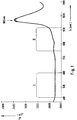
- Figure 1 shows an absorption spectrum of glucose in water.
- the decimal logarithm of the relation of measured intensity and irradiated intensity (lg I / I0) in transmission is plotted for a cuvette thickness of 1 cm and four glucose concentrations, namely 0.1.5 and 10%. It can be seen that the spectra for these four concentrations differ only slightly in a small wavelength range at approximately 980 nm. The maximum signal difference between the measured value with pure water and the 10% glucose solution at this wavelength is less than 2%. The difference is much smaller at other wavelengths.
- the variation of the glucose concentration used in the experiment is much larger than the real physiological glucose concentration. Based on a realistic glucose change in the physiological range of 100 mg / dl, the change at 980 nm corresponds to less than 0.02%.
- the change dI / dC of the measurement signal I as a function of the glucose concentration C is referred to below as "relative signal change" and is expressed quantitatively in% per 100 mg / dl change in the glucose concentration
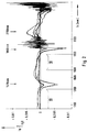
- FIG. 2 shows a similar spectrum in the subsequent wavelength range between approximately 1100 nm and 2500 nm. This is a difference spectrum for glucose concentrations between 0 and 600 mg / dl against pure water. Negative values mean a lower absorption compared to pure water. The maximum usable change in signal intensity is less than 0.3% overall, i.e. less than 0.05% on average per 100 mg / dl change in glucose concentration.
- Figures 1 and 2 show overall that the dependence of the absorption on the glucose concentration is so small over wide spectral ranges that it can practically not be used for measurement in a biological matrix.
- the spectral ranges with a "low" dependence of the absorption on the glucose concentration are the wavelength ranges in which the relative signal swing dI / dC in a transmission measurement on a clear glucose solution is less than 0.01% per 100 mg / dl change in the glucose concentration.
- the wavelengths around 980 nm, 1410 nm, 1890 nm and 2150 nm could be most suitable for the spectroscopic analysis of the glucose.
- the measurement should preferably be approximately monochromatic. "Monochromatic” is to be understood in the practical sense in that the major part of the intensity is emitted and / or detected in a relatively narrow wavelength range.
- the full width at half maximum should be less than 100 nm, preferably less than 50 nm.
- relatively broadband light sources such as light-emitting diodes or other semiconductor light sources can be used without subsequent spectral selection. This significantly reduces the cost of the equipment.
- the wavelength of the light source or the primary light, this statement relates to the wavelength of the intensity maximum.
- the at least two detection measurements are carried out at only one wavelength each.
- the fact that the measurement signal is largely independent of the wavelength makes it possible to select those wavelength ranges for the measurement in which the interference from strongly absorbing substances is as small as possible.
- the measured intensity is approximately independent of the concentration ratio between Hb and HbO2, because these substances have an isosbestic point there. This also applies in a broad isosbestic range between 1200 and 1300 nm.
- the absorption of hemoglobin and water is approximately the same in this range large. This results in a particularly good independence of the measured intensity from the ratio of Hb, HbO2 and H2O.
- a relative signal swing dI / dC is found in wavelength ranges in which the absorption has only a slight dependence on the glucose concentration, which is much larger than is to be expected on the basis of the absorption even in the narrow wavelength ranges , in which the absorption of the pure glucose solution is relatively strongly dependent on the glucose concentration.
- the value of the relative signal swing is dependent on the respective measurement setup, but is generally more than 0.5% per 100 mg / dl for measurements on human skin and is therefore at least ten times as large as the relative signal swing that is due to the change in absorption would be expected.
- the change in the glucose concentration leads to a change in the refractive index of the in the biological matrix contained liquid in which the glucose is dissolved.
- the change in the refractive index leads to a change in the light scattering at the scattering centers contained in the matrix.
- This change is extremely small for each individual spreading process.
- the change in the refractive index per mmol is only about 0.002%. In the context of the invention it was found that this extremely small effect for the analysis of glucose can be practically used if a large number of scattering processes of many photons which have undergone a mutually similar light path in the biological matrix are detected.
- the measuring method is thus designed in such a way that ideally the scattering behavior of the space surrounding the scattering centers, which is dependent on the refractive index, is determined within the biological matrix.
- this mechanism is very sensitive, i.e. the measured signals change strongly with relatively small changes in the glucose concentration.
- the increased sensitivity leads to improved selectivity compared to known in vivo analysis methods for glucose, because the variation of the multiple scattering used according to the invention in the most important biological matrices blood and skin tissue essentially depends only on the glucose concentration.
- MSAGD multiple scattering amplified glucose detection
- the effect on which the MSAGD is based represents a considerable disturbance in spectral analysis analyzes of other constituents of an optically heterogeneous biological matrix. It can therefore be advantageous to carry out at least one spatially resolved measurement of widely scattered light even with such a spectral analytical method for correcting changes in the optical path length caused by changes in the glucose concentration. Such a method is also the subject of the present invention.
- the MSAGD differs fundamentally from previous approaches to non-invasive analysis.
- infrared spectroscopy which is based on the measurement of the wavelength dependence of the absorption, the optical scattering is perceived as disturbing.
- parts of the body are selected where possible, which cause the least possible scattering of the light.
- NIR spectroscopic determinations on the antechamber of the eye which contains a relatively clear and therefore non-scattering liquid (US Pat. No. 4,014,321).
- the MSAGD signal also differs from absorption measurements in that the change in intensity as a function of the concentration dI / dC is largely independent of the wavelength.
- a certain change in the glucose concentration consequently leads to an approximately equal change in the intensity of the secondary light, even if the wavelength of the incident light differs by, for example, 100 nm.
- the change dI / dC in a more absorbing wavelength range is significantly higher than in a low-absorption wavelength range.
- This is used in spectroscopic measurements to use a wavelength with strong absorption as the measurement wavelength and a wavelength with weak absorption as the reference wavelength. This requires a narrow-band (“highly dispersive") measurement (with a half-value width less than 10 nm, often less than 1 nm) in a wide spectral range.
- Inexpensive semiconductor light transmitters in particular light-emitting diodes
- the location-dependent condition is to be understood such that the measurement of the secondary light (in contrast to EP-A-0 074 428) does not relate to a beam direction or an angular range of the light scattered by the measurement object or of the light reflected by the measurement object, but to one defined sub-area (area, district) of an interface delimiting the biological matrix, which is referred to as the detection site.
- the primary light is also irradiated in a defined partial area of an interface of the biological matrix, which is referred to as the irradiation site. Such a measurement is referred to as a "location-dependent detection measurement".
- the terms “irradiation site” and “detection site” are to be understood geometrically (for example in the sense of the English term “site”), namely as the partial area of the interface of a biological matrix on which light rays are decisive for the intensity measurement value in the respective detection measurement , pass through the interface.
- As a collective term for the place of entry and the detection location is therefore also referred to below as the "passage location”.
- the center of the irradiation site or the detection site Insofar as information about distances between passages is given below, these relate to the center of the irradiation site or the detection site. In the case of a circular design, the center is formed by the center point, in the case of an elongated design by the center line.
- the “multiple scattering condition” is to be understood in such a way that the places of passage (ie the irradiation site and the detection site) are arranged relative to one another in such a way that scattered light is detected at scattering centers of the biological matrix, the intensity of which is characteristic of the concentration of glucose. To ensure this, the following must be taken into account.
- the mean free path of photons in the tissue or the body fluids mentioned depends on the wavelength and the respective density and size of the scattering centers. It is typically between 0.01 mm and 0.1 mm. At least about 10, preferably at least about 100, scattering processes should take place on the light path in the biological matrix from the irradiation site to the detection site.
- the light path within the biological matrix is always longer (in many cases even considerably longer) than the direct connection between the radiation site and the detection site.
- the distance between the irradiation site and the detection site should correspond to at least ten times, preferably at least twenty times the mean free path of the photons in the respective biological matrix at the respective wavelength of the primary light.
- the maximum distance between the irradiation site and the detection site is also dependent on the mean free path of the photons. Above a limit to be determined experimentally in the individual case, the intensity of the signal drops in such a way that the signal / noise ratio becomes poor.
- the distance between the irradiation site and the detection site should preferably be less than 30 mm, particularly preferably less than 15 mm. In order to detect light that is widely scattered only at scattering centers of the biological matrix, care must also be taken to carefully shield the primary light from the detector with which the secondary light is measured.
- the multiple scattering means that the light emerging at the detection site is largely diffuse, i.e. its intensity is largely independent of the exit angle at which it is detected. If the primary light is coherent and / or polarized, these properties are largely lost due to the multiple scattering. For this reason, in general (unlike EP-A-0 074 428) the invention does not have to use a laser as the primary light source.
- the degree of polarization still obtained in the secondary light can also be used to test whether the "multiple scattering condition" required for the invention is fulfilled. For example, the degree of polarization of the secondary light should be less than 10% of an incident polarized primary light.
- the irradiation location and the detection location can have very different dimensions and geometrical shapes in the spatially resolved scattered light measurement. It is only essential that the spatially resolved scattered light measurement provides information about the intensity of the secondary light depending on the relative position of the irradiation site and the detection site (not depending on the detection angle). Several such spatially resolved measurements of widely scattered light, in which the respective detection location is at a different distance from the respective irradiation location, thus provide information I (D) about the functional dependence of the intensity I on the distance r.
- the irradiation location and especially the detection location in the case of spatially resolved scattered light measurement can have relatively large dimensions.
- embodiments are preferred in which the passage locations in the direction of the straight lines connecting the respective irradiation and detection locations (shortest connection) have a relatively small dimension of preferably less than 2 mm, particularly preferably less than 1 mm.
- the detection site is preferably located at the same interface as the irradiation site, i.e. it is measured "in reflection". As far as two opposite interfaces of the biological matrix are accessible, however, measurements can also be carried out “in transmission”, the radiation site and the detection location being on opposite interfaces of the biological matrix. In view of the diffuse nature of the light emerging at the detection location, the terms “transmission” and “reflection” must of course not be understood to mean that the secondary light emerges from the matrix with a strongly dominant preferred direction.
- the intensity measurement values of the at least two detection measurements are used to in one Evaluation step of the method using an evaluation algorithm and a calibration to determine the glucose concentration (“to be derived”). At least a first of these detection measurements must be a spatially resolved scattered light measurement. In principle, another method can also be used for a second detection measurement.
- Two or more spatially resolved scattered light measurements can also be carried out, from whose intensity measurements the glucose concentration is derived. It was found that from the dependency I (D) of the intensity I on the measuring distance D, which can be determined with at least two spatially resolved scattered light measurements, a particularly low-interference and therefore precise information about the glucose concentration is obtained.
- the two or more spatially resolved scattered light measurements are carried out at the same wavelength. If several light transmitters are used, it is sufficient if their wavelengths match the usual nominal fluctuations of light-emitting diodes with the same nominal wavelength.
- the term “light path” is of course not to be understood in the sense of a geometrically strictly limited partial volume of the biological matrix (as in classic transmission spectroscopy of a non-scattering liquid in a cuvette) because of the multiple scatter in the biological matrix.
- light path where it can be understood, for example, as the partial volume of the biological matrix in which a certain percentage (e.g. 70%) of the arriving from a certain irradiation location at a certain detection location, in which Matrix of widely scattered light is transported.
- a different light path in two spatially resolved scattered light measurements is realized in that the measuring distances between the irradiation site and the detection site differ sufficiently.
- the difference in intensity of the secondary light caused by the different light paths should make up at least a factor of 3, preferably at least a factor of 5, particularly preferably at least a factor of 10.
- An embodiment is particularly preferred in which at least two spatially resolving scattered light measurements with the same measuring distance between the irradiation site and the detection site are preferably carried out for two different measuring distances are carried out in which at least either the irradiation sites or the detection sites, preferably both the irradiation site and the detection site, differ.
- Such an embodiment does not seem sensible at first, because two measurements on the same biological matrix with the same length of light path should lead to the same result, i.e. no additional information would be obtained by the additional measurement.
- the additional measurement is redundant at the same measuring distance.
- redundant measurements are advantageous because they make it possible to identify and eliminate potential measurement errors due to inhomogeneities in the biological matrix (especially in skin tissue).
- the at least two detection measurements are preferably carried out simultaneously or at a sufficiently short time interval.
- a sufficiently short time interval is to be understood here at which there is no change in the biological matrix which impairs the measuring accuracy between the measurements which are used to derive a concentration value of the glucose.
- switchable irradiation means and / or detection means are provided in order to enable the setting of different pairs of passages without moving parts.
- the blood pulse can either be averaged over a sufficient number of pulse periods or measured synchronously with the pulse.
- the variation in body temperature can be recorded and used for compensation.
- the detection area in which the passage fields are located is actively thermostatted. Since a relatively high energy consumption is associated with such a temperature control, the measuring range is carefully thermally insulated in a device for in-vivo analysis preferred in the context of the invention.
- the invention does not differ significantly from known analysis methods which, as explained above, also require calibration in order to assign the measured variable (for example the color change in colorimetric tests) to the respective concentration.
- the algorithm in the present invention contains a simple predetermined mathematical function in order to determine an intermediate variable from the intensity measurement values I of the detection measurements, which can be referred to as the measurement result R.
- a simple quotient formation between the intensity measurement values of the first and second detection measurements has proven to be very effective.
- the measurement result R can then be linked in a known manner with the concentration C of glucose.
- an optically heterogeneous biological matrix 10 is shown symbolically as a cuboid in FIGS. 4 to 7. It is delimited by an upper interface 11a and a lower interface 11b.
- the biological matrix can be blood, for example, in which case the interfaces run along the inner walls of an optically transparent vessel (cuvette) in which the blood is for analytical in-vitro analysis.
- the biological matrix is a tissue, the interface is formed by the surface of the tissue.
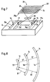
- FIGS. 4 to 8 illustrate different variants of possible arrangements of one or more irradiation locations 12 or one or more detection locations 14 on a biological matrix 10 in a spatially resolved scattered light measurement in the sense of the invention.
- the irradiation locations 12 are each designed as narrow, elongated radiation fields 12a-12f and the detection locations as elongated, narrow detection fields 14a-14i.
- Such an elongated shape of the passage locations 12, 14 has proven to be a practically well usable compromise between the requirements of a good spatial resolution and a sufficient intensity of the irradiated or measured light at a reasonable manufacturing cost.
- the length of a passage field should be at least three times, preferably at least ten times as large as its width.
- the average width of the passage fields is preferably at most 2 mm, particularly preferably at most 1 mm. As far as special features of the elongated shape are not important, similar considerations also apply to point or circular passages.
- the primary light 15 is irradiated into the matrix 10 by an irradiation field 12a and the secondary light 17 is detected, which emerges from two detection fields 14a and 14b running at different measuring distances D1 and D2 to the irradiation field 12a.
- the primary light 15 enters the biological matrix 10 through an irradiation field 12b and the secondary light 17 exits from it through two detection fields 14c and 14d, the detection fields at different lateral measurement distances D1 and D2 from the irradiation field 12b are arranged.
- the detection fields 14c and 14d are located on the interface 11b, that of the interface 11a through which the Primary light 15 is radiated, is opposite.
- the entry field and exit field are preferably arranged in such a way that, in the case of at least two pairs of passage fields, the surface of the exit field is not crossed by any straight line crossing the surface of the radiation field at right angles.
- the detection field should not be arranged exactly opposite the radiation field, but should always be laterally offset from it.
- the biological matrix is a tissue, in particular skin tissue
- an interface delimiting the matrix namely the surface of the skin
- the body parts preferred in the context of the invention namely the fingertip, the trunk, the nail bed, the sclera or the inner upper arm of the person.
- the measurement which is preferred in the context of the present invention in the reflection method is possible, in which the irradiation of the primary light and the detection of the secondary light take place at the same interface of the matrix.
- two opposite interfaces 11a, 11b are also available for the in vivo analysis on skin tissue.
- the primary light is emitted by two radiation fields 12c, 12d in the biological matrix 10 is irradiated and the secondary light 17 emerging from the detection field 14e is detected.
- the radiation fields 12d and 12c are arranged at different measuring distances D1 and D2 from the detection field 14e, so that in this embodiment there is also the possibility of measuring the secondary light emerging from the detection field 14e as a function of the measuring distance from the respective radiation field 12c or 12d in order to derive a measured variable from the two measured values which is a measure of the concentration of the analyte in the biological matrix.
- the secondary light components that result from the primary light of the two different radiation fields must of course be separated from one another. This can expediently be carried out by irradiation separated in time, but the irradiation must take place at a sufficiently narrow time interval in the sense of the definition given above.
- the maximum measuring distance D2 between an irradiation location and a detection location of a spatially resolved scattered light measurement is 30 mm.
- the shorter distance D1 should be at least 0.5 mm, preferably at least 1 mm.
- the detection locations lie in a detection area 16 (shown in dashed lines in the figure) which includes the part of the interface 11a which is at a distance of at least 0.5 mm, preferably at least 1 mm and at most 30 mm from the center of the irradiation location 12 has.
- the corresponding values apply to the irradiation region 18 shown in dashed lines there.
- FIG. 7 shows an embodiment in which a multiplicity of different detection fields 14f can be set on the interface 11a within a detection area 22, which run at different distances from an irradiation field 12e.
- this is achieved in that the detection area 22 is imaged by an optical imaging system symbolized as a lens 23 into an image plane 24 in which there is a two-dimensional arrangement 26 of light-sensitive elements, which are implemented, for example, as CCDs 25 (charge coupled device) .
- CCDs 25 charge coupled device
- the optical imaging corresponds to a specific detection field to a specific partial area of the CCD matrix 25.
- the field 14f is mapped to the row 25f and the field 14g to the row 25g of the CCD matrix 25.
- a specific detection field can consequently be set in a simple manner in that the intensity measurement signals are processed further by those light-sensitive elements to derive the concentration onto which the desired detection field is mapped.
- the terms “radiation field” and “detection field” or “radiation location” and “detection location” are to be understood geometrically. It is not absolutely necessary for any components of the analysis device to touch the interface of the biological matrix, for example the surface of the skin, and to be in contact with the radiation site or the detection site. It is only necessary that the irradiation location and the detection location are defined for each measuring distance, i.e. the primary light is radiated in at a specific and limited irradiation location and the secondary light is detected in such a locally defined manner that it is known from which specific delimited partial area of the interface (detection location) the secondary light has emerged, the intensity of which is detected in each case. Such a measuring process must take place with at least two different light paths between the irradiation site and the detection site in order to derive the measurement parameter characteristic of the analysis from the intensity measurement values measured therefrom.
- Figure 8 illustrates that the narrow, elongated shape of the fields need not necessarily be straight (as in Figures 4 to 7).
- a radiation field 12f in the form of a section of a circular ring is shown in a view of an interface.
- Two detection fields 14h and 14i likewise run in the form of circular ring sections at different distances from the radiation field 12f.
- the circular rings are concentric, so that the detection fields 14h and 14i are evenly spaced from the radiation field 12f.
- a good spatial resolution is achieved if the light is irradiated at a narrowly limited (point-shaped) radiation site and the detection site is one Forms a circle or section of a circle around this irradiation site.
- the detection site is one Forms a circle or section of a circle around this irradiation site.
- the passage fields (measured from center to center) run at a uniform distance D1, D2.
- the radiation site and the detection site should always be separated by a strip 47 (FIG. 8) of essentially uniform width.
- the dimension of the detection field in the direction of the shortest connection to the irradiation field (ie in the direction of the distance arrows D1, D2) should be less than 2 mm, preferably less than 1 mm, on average.
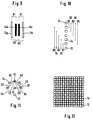
- Figures 9 to 12 show in a schematic representation (with a view of the interface) different arrangements in which redundant measurements are possible, i.e. several spatially resolved scattered light measurements with the same measuring distances and the same measuring wavelength, but different irradiation and / or detection locations.
- two elongated, rectangular detection fields 14k, 14l are arranged at equal distances between two likewise rectangular radiation fields 12g, 12h. All passage areas run parallel to each other. It is clear that a first measuring distance D1 can be set both by combining the radiation field 12g and the detection field 14k and by combining the radiation field 12h and the detection field 14l. A second larger measuring distance D2 results from the combination of the passage fields 12g with 14l or 12h with 14k.
- FIG. 10 shows a corresponding linear arrangement with two outer irradiation locations 12.
- Five detection locations 14 are arranged at regular intervals on the connecting line between the irradiation locations 12.
- all of the passages are point-shaped with a suitably round cross-section.
- the symbolic representation as squares and circles is only intended to facilitate the differentiation of the irradiation locations 12 and the detection locations 14.
- five different measuring distances D1 to D5 can each be set in two ways with different irradiation and detection locations, as shown in the figure.
- three irradiation locations 12 are combined with six detection locations.
- the irradiation locations 12 are arranged on a straight line at equal distances.
- the detection locations are located on a circle around the central irradiation location. In general, they should be distributed mirror-symmetrically around the straight line on which the irradiation locations are arranged. With this arrangement, there is a sixfold redundancy with respect to the central irradiation location 12 because each of the detection locations 14 is positioned at the same distance D1 from the central irradiation location.
- each of these irradiation locations is combined with two detection locations can, which are located in the corresponding distances D2 to D4.
- Such an arrangement enables high redundancy with relatively few components, because each measuring distance can be set with more than two different combinations of irradiation location 12 and detection location 14.
- arrangements with at least three different irradiation sites and at least three different detection sites are particularly preferred, which enable the setting of several different measuring distances, each with at least three different pairs of irradiation site and detection site. At least three times the redundancy has the advantage that it is generally recognizable if one of the stray light measurements from the other two stray light measurements deviates.
- the irradiation locations and the detection locations can be exchanged. For cost reasons, however, it is more advantageous to provide more detection sites than irradiation sites.
- a multiplicity of irradiation locations 12 and detection locations 14 are arranged alternately in a checkerboard fashion such that each irradiation location is surrounded by four detection locations and each detection location is surrounded by four irradiation locations.
- Redundant measurement arrangements make it possible to recognize and eliminate potential measurement errors due to inhomogeneities in the biological matrix. For this purpose, several measurements with the same measuring distances but different irradiation and / or detection locations are carried out and compared with one another. With a homogeneous structure of the examined biological matrix, the same intensity of the detected secondary light would have to be measured (with the same intensity of the incident primary light). Deviations suggest that disturbing structures (for example scars, hair or fibromas) are present in the examined partial area of the skin surface, which falsify the measurement result. This can be corrected in different ways.
- disturbing structures for example scars, hair or fibromas
- the measuring head placed on the skin can be moved to a different position in order to change the examined partial area of the skin surface ("measuring focus") so that the inhomogeneities lie outside the measuring focus.
- measuring focus the examined partial area of the skin surface
- averaging can be considered for a very large number of measurements. Of course, these measures can also be used in combination.
- the course of the measured intensity I is recorded as a function of the measuring distance D between the respective detection site and the irradiation site. If the detection locations are closely adjacent, a practically continuous curve I (D) results, which represents the profile of the detected secondary light as a function of the distance between the respective irradiation location and the respective detection location.
- a suitable regression algorithm known for such purposes can be used to derive the measurement variable characteristic of the analysis (for example PLS).
- the embodiment with a detection area in which a large number of different partial areas can be set as detection locations can of course also be implemented without the optical imaging system 23 shown in FIG. 7.
- suitable means such as, for example, screens, light guides or the like
- each light-sensitive element is made up of a specific Secondary light emerging from the delimited partial region of the interface 11a.
- Such an implementation is for the Embodiments according to FIGS. 10 to 12 are particularly suitable and can be integrated in one structural unit.
- both the irradiation location 12 and the detection location 14 should have a small dimension of at most 2 mm, preferably at most 1 mm, in the direction of the straight lines connecting the two fields.
- the different detection locations and / or irradiation locations by means of which the different measuring distances are realized are preferably spatially separated (not overlapping).
- An embodiment in which a multiplicity of different detection locations can be detected by means of a two-dimensional arrangement of light-sensitive elements opens up a number of additional possibilities, which are explained below.
- the detection locations should be adjustable in close succession.
- At least two, preferably at least four, particularly preferably at least eight different detection sites per cm can preferably be set in at least one dimension, particularly preferably in two dimensions.
- measuring focus On the one hand, it is possible to find a specific measuring position on a skin surface ("measuring focus"). For example, with the help of a pattern recognition process, characteristic structures of the surface can be recognized. Alternatively or additionally, a marking (for example by means of a tattoo that is invisible in normal light but contrasting in NIR light) can be provided by the skin two-dimensional arrangement of light-sensitive elements is recognized and localized.
- a second important possibility is the separation of the change in intensity caused by absorption on the one hand and scattering on the other.
- intensity profiles must be measured with the aid of a two-dimensional arrangement of light-sensitive elements at different wavelengths.
- an arrangement with many irradiation and detection locations arranged close to one another in a matrix-like manner can advantageously be used, alternating light with at least two different wavelengths being irradiated or detected in the matrix.
- the arrangement essentially corresponds to FIG. 12, apart from the use of several wavelengths, but not necessarily a regular checkerboard pattern with a regularly alternating arrangement of the irradiation and detection locations must be used.
- the number of different wavelengths preferably corresponds to the number of essential interference components plus a further wavelength.
- at least four different wavelengths are preferred with regard to the three most important interference components Hb, HbO2 and H2O.
- the influences of the scattering coefficient and the absorption coefficient can be separated from these measurement results by means of known procedures. Taking into account the knowledge of the present invention about the MSAGD effect, it is possible with such a two-dimensional multi-wavelength measurement to largely eliminate the interfering influences of the strongly absorbing substances when determining the glucose concentration by means of the present invention, or vice versa, for example, in a spectral analysis based determination of the concentration of Hb and HbO2 also largely suppress the disturbances that can be attributed to different glucose concentrations.
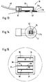
- FIGS. 13 to 15 show a practical embodiment of a measuring head 30 which is suitable for the invention and which is particularly suitable for the in vivo determination of glucose in human tissue.
- the measuring head 30 has a skin contact part 31 which is approximately circular in shape and which is fastened to a measuring head housing 32.
- the skin contact part 31 is placed on the surface of the skin 33 during use and lightly pressed.
- a square light transmission area 34 At its center is a square light transmission area 34, the is shown enlarged in FIG. It contains five rows 35 to 39 of optical fibers 29, which in the example shown consist of thirty-two fibers each with a diameter of 0.25 mm.
- the optical fibers 29 are each arranged in the light transmission region 34 such that their end faces lie flush in a common flat contact surface 42 and are in direct contact with the skin when the skin contact part 31 is placed on the skin 33.
- the row 35 of optical fibers defines an irradiation location.
- the optical fibers 29 of this series are connected by a cable 40 to a central unit, not shown, in which there is a preferably monochromatic light source, for example a light-emitting diode or a laser diode, the light of which is coupled into the optical fibers 29.
- the optical fibers 29 form light irradiation means 27 for specifically illuminating a defined irradiation location on a skin surface.
- part of the series 35 optical fibers is used to control the constancy of the light source.
- sixteen of the thirty-two fibers were used to irradiate the light and the other sixteen fibers to control the light intensity, the latter being combined separately from the former and fed to a photosensitive element.
- Photodiodes for example, which are arranged in the measuring head 30 can be used as the measuring receiver. It is useful for each row 36 to 39 of optical fibers 29, each a possible detection location define a common measuring receiver. The optical fibers of these rows are thus combined to a respective measuring receiver, at which the light emerging from these optical fibers is detected. The rows 36 to 39 of the optical fibers 29 together with the measurement receiver (not shown) each form detection means 28 for targeted measurement of the secondary light emerging at a defined detection location.
- the end faces of the optical fibers of the rows 35 to 39 each terminate flush or slightly protrude from the skin contact surface 42 which delimits the light emission region 34 downwards. This prevents light from reaching the skin surface directly from the irradiation location defined by row 35 to one of the detection sites defined by rows 36 to 39.
- the glass fibers of different rows are optically carefully separated from one another within the measuring head 30, so that no transmission of primary light to the detection means can take place.
- the measuring head 30 is intended in particular for monitoring the blood glucose level of diabetics.
- it is attached to a suitable location, for example on the upper abdominal wall on the skin. This can be done for example with the help of an adhesive tape.
- the contact surface 42 should be pressed on with a sufficiently firm and even pressure.
- the skin contact part 31 has a ring 31a, the diameter of which is substantially larger than that of the light transmission region 34. It consists of an opaque material and closes with its Edge 31b off the skin.
- the primary light can be modulated with a certain frequency and can be selectively detected in a narrow-band manner depending on the frequency (for example with the aid of a lock-in amplifier), in order to reduce the effects of stray light.
- the light transmission region 34 is surrounded by an annular heating surface 41, in which a surface resistance heater is arranged. This can be regulated to a predetermined temperature, for example 37 °, with the aid of an NTC resistor and a PD controller.
- FIG. 16 shows analysis results which were achieved on the one hand with a reference method and on the other hand with a device according to the invention (embodiment according to FIGS. 13 to 15).
- the concentration C is plotted in mmol / l over the time t in minutes.
- the solid line 45 marks the results of an enzymatic analysis of the glucose in the patient's blood used as a reference method, while the rectangular markings are 46 measuring points with the device according to the invention.
- a measuring head according to FIGS. 13 to 15 was used, the light from a light-emitting diode with 1 mW power and a wavelength of 805 nm being radiated into the skin through the optical fiber series 35 and detected through the series 38 and 39.
- R characteristic of the concentration the quotient was formed between the intensity I1 of the light measured on the row 39 and the intensity I2 of the light measured on the row 38.
- FIG. 16 shows an excellent agreement between the conventionally in vitro blood and the values according to the invention in vivo in the skin tissue over a period of five and a half hours.
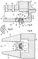
- FIGS. 17 and 18 show a measuring holder 50 for determining the glucose concentration in a finger 51.
- the finger 51 is inserted into a precisely fitting channel 52 which is formed in a holder block 53.
- the mounting block 53 consists of aluminum or another good heat-conducting material, which is set with a heating and thermostating device, not shown, to a defined temperature, which is preferably slightly above the normal body temperature (above 37 ° C.).
- the wall element 54 which laterally delimits the channel 52 can be displaced such that the width of the channel 52 can be adapted to the finger 51 of the respective patient.
- fixing elements 55 are provided which are slidably guided in the direction of the finger 51 and are pressed against the finger 51 with a spring (not shown).
- the mounting block 53, the wall elements 54 and the fixing elements 55 together form the channel 52 stop 56 delimiting in the insertion direction overall fixation means, by means of which the finger 51 is positioned in a position that is as reproducible as possible with respect to the measuring device designated overall by 58.
- light irradiation means 27 are formed by a light-emitting diode (not shown) and by a light guide channel 59, through which primary light is directed to a circular irradiation site of approximately 1 mm in diameter on the underside of the tip of the finger 51.
- a detection area 16 three detection locations 14 are provided which concentrically surround the irradiation site 12 as semicircular detection fields 14k-14m.
- the detection means 28 as can be seen more clearly in FIG.
- An infrared temperature sensor 60 is directed to a temperature measuring location 61 which should be as close as possible to the detection area 16.
- FIG. 20 shows an example of the block diagram of an electronic circuit 65 which is suitable as an evaluation means for a measuring device according to the invention.
- a voltage-current converter 67 is driven by an oscillator 66 and feeds the light-emitting diode 68, which serves as a light source.
- the temperature of the light-emitting diode 68 can optionally be monitored by an NTC 69 in order to improve the constancy of the intensity of the emitted light.
- the output signals of the measuring receivers (photodiodes) 70a-70c are applied to lock-in amplifiers 72a-72c via a preamplifier circuit 71a-71c, to which the signal of the oscillator 66 is also fed as a reference.
- the output signals of the lock-in amplifiers 72a-72c are digitized in an A / D converter unit 73 and fed to a microcomputer central unit 74.
- the microcomputer central unit furthermore receives the signals of the NTC 69 (amplified by a preamplifier 69a) and a temperature sensor 75 (amplified by a preamplifier 75a) for measuring the temperature in the detection area, which preferably (like the IR sensor 60 of the embodiment according to FIG 17) works without contact.
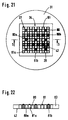
- semiconductor light receivers 80 for example photodiodes
- semiconductor light transmitters 81 for example light emitting diodes
- the semiconductor light transmitter 80 and the semiconductor light receiver 81 are integrated in the same component 83, the arrangement being shown only schematically without structural details.
- the practical implementation can be carried out using an integration technology customary in electronics, for example by monolithic integration in a chip or in hybrid technology. It is essential that both the light transmitters 81 and the light receivers 80 are in direct optical contact with the skin surface and are shielded from the neighboring elements so that they radiate the light into a defined irradiation location or detect it at a defined detection location.
- semiconductor light transmitter 81a and semiconductor light receiver 80a are drawn in white for a first wavelength, while semiconductor light transmitter 81b and semiconductor light receiver 80b are shown hatched for a second wavelength.
- both the setting of different measuring distances D and the setting of different wavelengths (if at all necessary) are carried out without moving parts. This is usually advantageous in terms of cost and reliability. Of course, alternatives with moving parts are also possible within the scope of the invention.
- Different measuring distances D can thus be set in that either the light irradiation means 27 or the detection means 28, for example with the aid of a spindle drive, the course I (D) of the intensity I being determined as a function of the measuring distance D by stepwise adjustment of this drive.
- a grating monochromator can be provided on the primary side or on the secondary side.
Landscapes
- Health & Medical Sciences (AREA)
- Life Sciences & Earth Sciences (AREA)
- Physics & Mathematics (AREA)
- Medical Informatics (AREA)
- Surgery (AREA)
- Biophysics (AREA)
- Pathology (AREA)
- Engineering & Computer Science (AREA)
- Biomedical Technology (AREA)
- Heart & Thoracic Surgery (AREA)
- Veterinary Medicine (AREA)
- Molecular Biology (AREA)
- Public Health (AREA)
- Animal Behavior & Ethology (AREA)
- General Health & Medical Sciences (AREA)
- Optics & Photonics (AREA)
- Spectroscopy & Molecular Physics (AREA)
- Emergency Medicine (AREA)
- Measurement Of The Respiration, Hearing Ability, Form, And Blood Characteristics Of Living Organisms (AREA)
- Investigating Or Analysing Biological Materials (AREA)
- Investigating Or Analysing Materials By Optical Means (AREA)
- Measuring And Recording Apparatus For Diagnosis (AREA)
- Measuring Or Testing Involving Enzymes Or Micro-Organisms (AREA)
Applications Claiming Priority (12)
| Application Number | Priority Date | Filing Date | Title |
|---|---|---|---|
| DK136392 | 1992-11-09 | ||
| DK136392A DK136392A (da) | 1992-11-09 | 1992-11-09 | Fremgangsmåde og apparat til måling af koncentrationen af et opløst stof i en væske |
| DK1363/92 | 1992-11-09 | ||
| DK044693A DK44693A (da) | 1992-11-09 | 1993-04-20 | Fremgangsmåde og apparat til kompenseret måling af koncentration |
| DK446/93 | 1993-04-20 | ||
| DK44693 | 1993-04-20 | ||
| DK045793A DK45793A (da) | 1992-11-09 | 1993-04-21 | Fremgangsmåde og apparat til kompenseret måling af koncentration |
| DK457/93 | 1993-04-21 | ||
| DK45793 | 1993-04-21 | ||
| DE4314835A DE4314835A1 (de) | 1993-05-05 | 1993-05-05 | Verfahren und Vorrichtung zur Analyse von Glucose in einer biologischen Matrix |
| DE4314835 | 1993-05-05 | ||
| EP93924502A EP0659055B1 (fr) | 1992-11-09 | 1993-11-04 | Procede et dispositif d'analyse de glucose dans une matrice biologique |
Related Parent Applications (2)
| Application Number | Title | Priority Date | Filing Date |
|---|---|---|---|
| EP93924502A Division-Into EP0659055B1 (fr) | 1992-11-09 | 1993-11-04 | Procede et dispositif d'analyse de glucose dans une matrice biologique |
| EP93924502.3 Division | 1994-05-26 |
Publications (2)
| Publication Number | Publication Date |
|---|---|
| EP0707826A1 true EP0707826A1 (fr) | 1996-04-24 |
| EP0707826B1 EP0707826B1 (fr) | 1999-06-09 |
Family
ID=27435737
Family Applications (2)
| Application Number | Title | Priority Date | Filing Date |
|---|---|---|---|
| EP93924502A Expired - Lifetime EP0659055B1 (fr) | 1992-11-09 | 1993-11-04 | Procede et dispositif d'analyse de glucose dans une matrice biologique |
| EP95116266A Expired - Lifetime EP0707826B1 (fr) | 1992-11-09 | 1993-11-04 | Procédé et appareil pour la détermination du glucose contenu dans un milieu biologique |
Family Applications Before (1)
| Application Number | Title | Priority Date | Filing Date |
|---|---|---|---|
| EP93924502A Expired - Lifetime EP0659055B1 (fr) | 1992-11-09 | 1993-11-04 | Procede et dispositif d'analyse de glucose dans une matrice biologique |
Country Status (17)
| Country | Link |
|---|---|
| US (2) | US5551422A (fr) |
| EP (2) | EP0659055B1 (fr) |
| JP (1) | JP3396222B2 (fr) |
| KR (1) | KR0170040B1 (fr) |
| AT (1) | ATE136443T1 (fr) |
| AU (1) | AU674555B2 (fr) |
| CA (1) | CA2147639C (fr) |
| DE (3) | DE59309645D1 (fr) |
| DK (1) | DK0659055T3 (fr) |
| ES (2) | ES2133643T3 (fr) |
| FI (1) | FI951673A7 (fr) |
| GR (1) | GR3020063T3 (fr) |
| HK (1) | HK201896A (fr) |
| IL (1) | IL107396A (fr) |
| NO (1) | NO951792D0 (fr) |
| TW (1) | TW305022B (fr) |
| WO (1) | WO1994010901A1 (fr) |
Cited By (3)
| Publication number | Priority date | Publication date | Assignee | Title |
|---|---|---|---|---|
| WO1997027469A1 (fr) * | 1996-01-26 | 1997-07-31 | Boehringer Mannheim Gmbh | Procede et dispositif de determination d'un analyte contenu dans une matrice de diffusion |
| WO2002040971A1 (fr) * | 2000-11-15 | 2002-05-23 | Bang & Olufsen Medicom A/S | Procede et appareil permettant de determiner des parametres optiques de fluide trouble et utilisation associee |
| EP1245192A4 (fr) * | 1999-12-27 | 2005-11-30 | Hitachi Ltd | Dispositif photmetrique biologique |
Families Citing this family (290)
| Publication number | Priority date | Publication date | Assignee | Title |
|---|---|---|---|---|
| US5353799A (en) * | 1991-01-22 | 1994-10-11 | Non Invasive Technology, Inc. | Examination of subjects using photon migration with high directionality techniques |
| US5782755A (en) * | 1993-11-15 | 1998-07-21 | Non-Invasive Technology, Inc. | Monitoring one or more solutes in a biological system using optical techniques |
| US6725072B2 (en) * | 1990-10-06 | 2004-04-20 | Hema Metrics, Inc. | Sensor for transcutaneous measurement of vascular access blood flow |
| US6549795B1 (en) | 1991-05-16 | 2003-04-15 | Non-Invasive Technology, Inc. | Spectrophotometer for tissue examination |
| US6785568B2 (en) * | 1992-05-18 | 2004-08-31 | Non-Invasive Technology Inc. | Transcranial examination of the brain |
| DE4337570A1 (de) * | 1993-11-04 | 1995-05-11 | Boehringer Mannheim Gmbh | Verfahren zur Analyse von Glucose in einer biologischen Matrix |
| US6493565B1 (en) | 1993-11-15 | 2002-12-10 | Non-Invasive Technology, Inc. | Examination of biological tissue by monitoring one or more solutes |
| US5492118A (en) * | 1993-12-16 | 1996-02-20 | Board Of Trustees Of The University Of Illinois | Determining material concentrations in tissues |
| DE4417639A1 (de) * | 1994-05-19 | 1995-11-23 | Boehringer Mannheim Gmbh | Verfahren zur Bestimmung eines Analyten in einer biologischen Probe |
| US6153109A (en) | 1994-09-16 | 2000-11-28 | Transonic Systmes, Inc. | Method and apparatus to measure blood flow rate in hemodialysis shunts |
| US6514419B2 (en) | 1994-09-16 | 2003-02-04 | Transonic Systems, Inc. | Method to measure blood flow and recirculation in hemodialysis shunts |
| US5803909A (en) | 1994-10-06 | 1998-09-08 | Hitachi, Ltd. | Optical system for measuring metabolism in a body and imaging method |
| US6957094B2 (en) * | 1994-12-02 | 2005-10-18 | Non-Invasive Technology, Inc. | Examination of scattering properties of biological tissue |
| DE4446721C2 (de) * | 1994-12-24 | 2002-02-28 | Roche Diagnostics Gmbh | System und Verfahren zur Bestimmung von Eigenschaften von Gewebeteilen |
| JP2807650B2 (ja) * | 1994-12-24 | 1998-10-08 | ベーリンガー・マンハイム・ゲゼルシャフト・ミット・ベシュレンクテル・ハフツング | 組織の特性決定のための装置 |
| US6618614B1 (en) | 1995-01-03 | 2003-09-09 | Non-Invasive Technology, Inc. | Optical examination device, system and method |
| US20050043596A1 (en) * | 1996-07-12 | 2005-02-24 | Non-Invasive Technology, Inc., A Delaware Corporation | Optical examination device, system and method |
| JP3725156B2 (ja) * | 1995-01-03 | 2005-12-07 | ノン−インヴェイシヴ テクノロジイ,インク. | 生物組織の生体内検査用の光学カプラ |
| US5657754A (en) * | 1995-07-10 | 1997-08-19 | Rosencwaig; Allan | Apparatus for non-invasive analyses of biological compounds |
| GB9515648D0 (en) * | 1995-07-31 | 1995-09-27 | Johnson & Johnson Medical | Apparatus for non-invasive measurement within a human or animal body |
| US6240306B1 (en) * | 1995-08-09 | 2001-05-29 | Rio Grande Medical Technologies, Inc. | Method and apparatus for non-invasive blood analyte measurement with fluid compartment equilibration |
| WO1997018755A1 (fr) * | 1995-11-17 | 1997-05-29 | Hitachi, Ltd. | Instrument servant a des mesures optiques sur des corps vivants |
| US6240309B1 (en) | 1995-10-06 | 2001-05-29 | Hitachi, Ltd. | Optical measurement instrument for living body |
| DE19543020A1 (de) | 1995-11-18 | 1997-05-22 | Boehringer Mannheim Gmbh | Verfahren und Vorrichtung zur Bestimmung von analytischen Daten über das Innere einer streuenden Matrix |
| DE19544501A1 (de) | 1995-11-29 | 1997-06-05 | Boehringer Mannheim Gmbh | Vorrichtung für Lichtreflexionsmessungen |
| US6405069B1 (en) | 1996-01-31 | 2002-06-11 | Board Of Regents, The University Of Texas System | Time-resolved optoacoustic method and system for noninvasive monitoring of glucose |
| ATE209017T1 (de) * | 1996-02-05 | 2001-12-15 | Diasense Inc | Vorrichtung zur nicht-invasiven bestimmung von glukose |
| US6544193B2 (en) * | 1996-09-04 | 2003-04-08 | Marcio Marc Abreu | Noninvasive measurement of chemical substances |
| US5800349A (en) * | 1996-10-15 | 1998-09-01 | Nonin Medical, Inc. | Offset pulse oximeter sensor |
| JP4212007B2 (ja) * | 1996-11-26 | 2009-01-21 | パナソニック電工株式会社 | 血液成分濃度の分析装置 |
| US6122042A (en) * | 1997-02-07 | 2000-09-19 | Wunderman; Irwin | Devices and methods for optically identifying characteristics of material objects |
| US5910109A (en) * | 1997-02-20 | 1999-06-08 | Emerging Technology Systems, Llc | Non-invasive glucose measuring device and method for measuring blood glucose |
| US6161028A (en) * | 1999-03-10 | 2000-12-12 | Optiscan Biomedical Corporation | Method for determining analyte concentration using periodic temperature modulation and phase detection |
| TW352335B (en) * | 1997-03-25 | 1999-02-11 | Matsushita Electric Works Ltd | Method of determining a glucose concentration in a target by using near-infrared spectroscopy |
| DE19721902A1 (de) | 1997-05-26 | 1998-12-03 | Boehringer Mannheim Gmbh | Verfahren und Vorrichtung zur in-vivo-Detektion der Richtung von Langer-Linien in der Haut |
| JP3758823B2 (ja) * | 1997-08-06 | 2006-03-22 | 倉敷紡績株式会社 | 生体の位置決め装置 |
| WO1999000053A1 (fr) * | 1997-06-27 | 1999-01-07 | Toa Medical Electronics Co., Ltd. | Dispositif permettant d'examiner un organisme vivant et automate permettant d'analyser le sang d'une maniere non invasive au moyen dudit dispositif |
| US6343223B1 (en) * | 1997-07-30 | 2002-01-29 | Mallinckrodt Inc. | Oximeter sensor with offset emitters and detector and heating device |
| US6115621A (en) * | 1997-07-30 | 2000-09-05 | Nellcor Puritan Bennett Incorporated | Oximetry sensor with offset emitters and detector |
| JP3758824B2 (ja) * | 1997-08-06 | 2006-03-22 | 倉敷紡績株式会社 | 生体の圧力一定化装置 |
| US7039446B2 (en) * | 2001-01-26 | 2006-05-02 | Sensys Medical, Inc. | Indirect measurement of tissue analytes through tissue properties |
| US6036924A (en) | 1997-12-04 | 2000-03-14 | Hewlett-Packard Company | Cassette of lancet cartridges for sampling blood |
| US6163154A (en) * | 1997-12-23 | 2000-12-19 | Magnetic Diagnostics, Inc. | Small scale NMR spectroscopic apparatus and method |
| EP1051106B1 (fr) * | 1998-01-27 | 2004-09-15 | Lightouch Medical, Inc. | Procede et dispositif pour la modulation tissulaire |
| US6804543B2 (en) * | 1998-02-05 | 2004-10-12 | Hema Metrics, Inc. | Sensor for transcutaneous measurement of vascular access blood flow |
| WO1999040841A1 (fr) * | 1998-02-11 | 1999-08-19 | Non-Invasive Technology, Inc. | Visualisation et caracterisation du tissu cerebral |
| DE69934482T2 (de) * | 1998-02-11 | 2007-09-27 | Non-Invasive Technology, Inc. | Nachweis, abbildung und kennzeichnung von brustumoren |
| WO1999040842A1 (fr) * | 1998-02-13 | 1999-08-19 | Non-Invasive Technology, Inc. | Examen transabdominal, surveillance et imagerie tissulaires |
| US20070167704A1 (en) * | 1998-02-13 | 2007-07-19 | Britton Chance | Transabdominal examination, monitoring and imaging of tissue |
| US6391005B1 (en) | 1998-03-30 | 2002-05-21 | Agilent Technologies, Inc. | Apparatus and method for penetration with shaft having a sensor for sensing penetration depth |
| US20020091324A1 (en) * | 1998-04-06 | 2002-07-11 | Nikiforos Kollias | Non-invasive tissue glucose level monitoring |
| US6505059B1 (en) | 1998-04-06 | 2003-01-07 | The General Hospital Corporation | Non-invasive tissue glucose level monitoring |
| US6728560B2 (en) | 1998-04-06 | 2004-04-27 | The General Hospital Corporation | Non-invasive tissue glucose level monitoring |
| US7899518B2 (en) | 1998-04-06 | 2011-03-01 | Masimo Laboratories, Inc. | Non-invasive tissue glucose level monitoring |
| US6721582B2 (en) | 1999-04-06 | 2004-04-13 | Argose, Inc. | Non-invasive tissue glucose level monitoring |
| ATE269663T1 (de) | 1998-04-24 | 2004-07-15 | Lightouch Medical Inc | Gerät und verfahren zur thermischen modulation von gewebe |
| US6526298B1 (en) | 1998-05-18 | 2003-02-25 | Abbott Laboratories | Method for the non-invasive determination of analytes in a selected volume of tissue |
| US6662031B1 (en) | 1998-05-18 | 2003-12-09 | Abbott Laboratoies | Method and device for the noninvasive determination of hemoglobin and hematocrit |
| US7043287B1 (en) | 1998-05-18 | 2006-05-09 | Abbott Laboratories | Method for modulating light penetration depth in tissue and diagnostic applications using same |
| US6241663B1 (en) * | 1998-05-18 | 2001-06-05 | Abbott Laboratories | Method for improving non-invasive determination of the concentration of analytes in a biological sample |
| US6662030B2 (en) | 1998-05-18 | 2003-12-09 | Abbott Laboratories | Non-invasive sensor having controllable temperature feature |
| IL124787A0 (en) * | 1998-06-07 | 1999-01-26 | Itamar Medical C M 1997 Ltd | Pressure applicator devices particularly useful for non-invasive detection of medical conditions |
| WO2000001295A1 (fr) | 1998-07-07 | 2000-01-13 | Lightouch Medical, Inc. | Processus de modulation tissulaire destine a l'analyse spectroscopique quantitative non invasive in vivo des tissus |
| US6678541B1 (en) * | 1998-10-28 | 2004-01-13 | The Governmemt Of The United States Of America | Optical fiber probe and methods for measuring optical properties |
| JP2000155090A (ja) * | 1998-11-20 | 2000-06-06 | Fuji Photo Film Co Ltd | 血管の画像化装置 |
| US6353226B1 (en) | 1998-11-23 | 2002-03-05 | Abbott Laboratories | Non-invasive sensor capable of determining optical parameters in a sample having multiple layers |
| US6615061B1 (en) | 1998-11-23 | 2003-09-02 | Abbott Laboratories | Optical sensor having a selectable sampling distance for determination of analytes |
| US6584340B1 (en) * | 1998-12-24 | 2003-06-24 | Matsushita Electric Industrial Co., Ltd. | Living body information measuring apparatus living body information measuring method body fat measuring apparatus body fat measuring method and program recording medium |
| JP3763687B2 (ja) * | 1998-12-25 | 2006-04-05 | 三井金属鉱業株式会社 | 血糖値測定装置 |
| US6305804B1 (en) | 1999-03-25 | 2001-10-23 | Fovioptics, Inc. | Non-invasive measurement of blood component using retinal imaging |
| US7299080B2 (en) * | 1999-10-08 | 2007-11-20 | Sensys Medical, Inc. | Compact apparatus for noninvasive measurement of glucose through near-infrared spectroscopy |
| US6424416B1 (en) | 1999-10-25 | 2002-07-23 | Textron Systems Corporation | Integrated optics probe for spectral analysis |
| US6836325B2 (en) | 1999-07-16 | 2004-12-28 | Textron Systems Corporation | Optical probes and methods for spectral analysis |
| US7840257B2 (en) | 2003-01-04 | 2010-11-23 | Non Invasive Technology, Inc. | Examination of biological tissue using non-contact optical probes |
| US7904139B2 (en) | 1999-08-26 | 2011-03-08 | Non-Invasive Technology Inc. | Optical examination of biological tissue using non-contact irradiation and detection |
| US6411373B1 (en) | 1999-10-08 | 2002-06-25 | Instrumentation Metrics, Inc. | Fiber optic illumination and detection patterns, shapes, and locations for use in spectroscopic analysis |
| US6868739B1 (en) | 1999-10-19 | 2005-03-22 | Transonic Systems, Inc. | Method and apparatus to measure blood flow by an introduced volume change |
| US6361960B1 (en) | 1999-11-09 | 2002-03-26 | Environmentally Sensitive Solutions, Inc. | Method and test kit for measuring concentration of a cleaning agent in a wash liquor |
| US6418805B1 (en) | 1999-11-18 | 2002-07-16 | Textron Systems Corporation | Constituent sensing system |
| CN1209074C (zh) * | 2000-02-03 | 2005-07-06 | 浜松光子学株式会社 | 非侵袭性生物体光计测装置 |
| CA2400305A1 (fr) | 2000-02-18 | 2001-08-23 | Argose,Inc. | Generation de cartes d'excitation-emission spatialement moyennees dans des tissus heterogenes |
| DE60137599D1 (de) | 2000-03-10 | 2009-03-19 | Textron Systems Corp | Optische sonden und verfahren zur spektralanalyse |
| US7509153B2 (en) * | 2000-09-26 | 2009-03-24 | Sensys Medical, Inc. | Method and apparatus for control of skin perfusion for indirect glucose measurement |
| IL136673A0 (en) | 2000-06-11 | 2001-06-14 | Orsense Ltd | A method and device for measuring the concentration of glucose or other substance in blood |
| US7050842B2 (en) | 2000-07-11 | 2006-05-23 | Lightouch Medical, Inc. | Method of tissue modulation for noninvasive measurement of an analyte |
| US6477393B1 (en) | 2000-07-19 | 2002-11-05 | Trw Inc. | Non-invasive blood glucose measurement techniques |
| US6587703B2 (en) | 2000-09-18 | 2003-07-01 | Photonify Technologies, Inc. | System and method for measuring absolute oxygen saturation |
| US6516209B2 (en) | 2000-08-04 | 2003-02-04 | Photonify Technologies, Inc. | Self-calibrating optical imaging system |
| US6597931B1 (en) | 2000-09-18 | 2003-07-22 | Photonify Technologies, Inc. | System and method for absolute oxygen saturation |
| WO2002012854A2 (fr) * | 2000-08-04 | 2002-02-14 | Photonify Technologies, Inc. | Systemes et procedes permettant d'obtenir des informations concernant des chromophores presents dans des milieux physiologiques |
| US6549861B1 (en) | 2000-08-10 | 2003-04-15 | Euro-Celtique, S.A. | Automated system and method for spectroscopic analysis |
| WO2002015782A1 (fr) * | 2000-08-18 | 2002-02-28 | Masimo Corporation | Hematometre pour doigt a application laterale |
| US6675030B2 (en) | 2000-08-21 | 2004-01-06 | Euro-Celtique, S.A. | Near infrared blood glucose monitoring system |
| IL138683A0 (en) * | 2000-09-25 | 2001-10-31 | Vital Medical Ltd | Apparatus and method for monitoring tissue vitality parameters |
| US8641644B2 (en) | 2000-11-21 | 2014-02-04 | Sanofi-Aventis Deutschland Gmbh | Blood testing apparatus having a rotatable cartridge with multiple lancing elements and testing means |
| DE10057832C1 (de) | 2000-11-21 | 2002-02-21 | Hartmann Paul Ag | Blutanalysegerät |
| US6746407B2 (en) * | 2000-12-29 | 2004-06-08 | Hema Metrics, Inc. | Method of measuring transcutaneous access blood flow |
| CA2441078A1 (fr) * | 2001-01-26 | 2002-08-22 | Sensys Medical, Inc. | Mesure non invasive du glucose en fonction des proprietes optiques du tissu |
| DE10203720B4 (de) | 2001-02-02 | 2012-11-22 | Nippon Telegraph And Telephone Corp. | Blutflußmesser und Sensorteil des Blutflußmessers |
| DE10110599A1 (de) | 2001-03-06 | 2002-09-12 | Roche Diagnostics Gmbh | Verfahren zur Bestimmung eines Lichttransportparameters in einer biologischen Matrix |
| US6952603B2 (en) | 2001-03-16 | 2005-10-04 | Roche Diagnostics Operations, Inc. | Subcutaneous analyte sensor |
| US7167734B2 (en) | 2001-04-13 | 2007-01-23 | Abbott Laboratories | Method for optical measurements of tissue to determine disease state or concentration of an analyte |
| ATE485766T1 (de) | 2001-06-12 | 2010-11-15 | Pelikan Technologies Inc | Elektrisches betätigungselement für eine lanzette |
| CA2448681C (fr) | 2001-06-12 | 2014-09-09 | Pelikan Technologies, Inc. | Systeme integre de prelevement et d'analyse d'echantillons sanguins avec module de prelevement a utilisation multiple |
| US8337419B2 (en) | 2002-04-19 | 2012-12-25 | Sanofi-Aventis Deutschland Gmbh | Tissue penetration device |
| US7981056B2 (en) | 2002-04-19 | 2011-07-19 | Pelikan Technologies, Inc. | Methods and apparatus for lancet actuation |
| AU2002312521A1 (en) | 2001-06-12 | 2002-12-23 | Pelikan Technologies, Inc. | Blood sampling apparatus and method |
| US9795747B2 (en) | 2010-06-02 | 2017-10-24 | Sanofi-Aventis Deutschland Gmbh | Methods and apparatus for lancet actuation |
| US7041068B2 (en) | 2001-06-12 | 2006-05-09 | Pelikan Technologies, Inc. | Sampling module device and method |
| ATE497731T1 (de) | 2001-06-12 | 2011-02-15 | Pelikan Technologies Inc | Gerät zur erhöhung der erfolgsrate im hinblick auf die durch einen fingerstich erhaltene blutausbeute |
| US9226699B2 (en) | 2002-04-19 | 2016-01-05 | Sanofi-Aventis Deutschland Gmbh | Body fluid sampling module with a continuous compression tissue interface surface |
| ES2336081T3 (es) | 2001-06-12 | 2010-04-08 | Pelikan Technologies Inc. | Dispositivo de puncion de auto-optimizacion con medios de adaptacion a variaciones temporales en las propiedades cutaneas. |
| AU2002348683A1 (en) | 2001-06-12 | 2002-12-23 | Pelikan Technologies, Inc. | Method and apparatus for lancet launching device integrated onto a blood-sampling cartridge |
| US9427532B2 (en) | 2001-06-12 | 2016-08-30 | Sanofi-Aventis Deutschland Gmbh | Tissue penetration device |
| US6650915B2 (en) * | 2001-09-13 | 2003-11-18 | Fovioptics, Inc. | Non-invasive measurement of blood analytes using photodynamics |
| US7344894B2 (en) | 2001-10-16 | 2008-03-18 | Agilent Technologies, Inc. | Thermal regulation of fluidic samples within a diagnostic cartridge |
| US20050010091A1 (en) * | 2003-06-10 | 2005-01-13 | Woods Joe W. | Non-invasive measurement of blood glucose using retinal imaging |
| US6989891B2 (en) * | 2001-11-08 | 2006-01-24 | Optiscan Biomedical Corporation | Device and method for in vitro determination of analyte concentrations within body fluids |
| DE10163972B4 (de) * | 2001-12-22 | 2005-10-27 | Roche Diagnostics Gmbh | Verfahren und Vorrichtung zur Bestimmung eines Lichttransportparameters und eines Analyten in einer biologischen Matrix |
| DE20213607U1 (de) | 2002-02-21 | 2003-07-03 | Paul Hartmann AG, 89522 Heidenheim | Blutanalysegerät zur Bestimmung eines Analyten |
| IL148795A0 (en) * | 2002-03-20 | 2002-09-12 | Vital Medical Ltd | Apparatus and method for monitoring tissue vitality parameters for the diagnosis of body metabolic emergency state |
| US20060161055A1 (en) * | 2002-03-20 | 2006-07-20 | Critisense, Ltd. | Probe design |
| US7374544B2 (en) | 2002-04-19 | 2008-05-20 | Pelikan Technologies, Inc. | Method and apparatus for penetrating tissue |
| US7175642B2 (en) | 2002-04-19 | 2007-02-13 | Pelikan Technologies, Inc. | Methods and apparatus for lancet actuation |
| US7717863B2 (en) | 2002-04-19 | 2010-05-18 | Pelikan Technologies, Inc. | Method and apparatus for penetrating tissue |
| US7901362B2 (en) | 2002-04-19 | 2011-03-08 | Pelikan Technologies, Inc. | Method and apparatus for penetrating tissue |
| US7491178B2 (en) | 2002-04-19 | 2009-02-17 | Pelikan Technologies, Inc. | Method and apparatus for penetrating tissue |
| US7909778B2 (en) | 2002-04-19 | 2011-03-22 | Pelikan Technologies, Inc. | Method and apparatus for penetrating tissue |
| US8784335B2 (en) | 2002-04-19 | 2014-07-22 | Sanofi-Aventis Deutschland Gmbh | Body fluid sampling device with a capacitive sensor |
| US9795334B2 (en) | 2002-04-19 | 2017-10-24 | Sanofi-Aventis Deutschland Gmbh | Method and apparatus for penetrating tissue |
| US8702624B2 (en) | 2006-09-29 | 2014-04-22 | Sanofi-Aventis Deutschland Gmbh | Analyte measurement device with a single shot actuator |
| US9314194B2 (en) | 2002-04-19 | 2016-04-19 | Sanofi-Aventis Deutschland Gmbh | Tissue penetration device |
| US7232451B2 (en) | 2002-04-19 | 2007-06-19 | Pelikan Technologies, Inc. | Method and apparatus for penetrating tissue |
| US8579831B2 (en) | 2002-04-19 | 2013-11-12 | Sanofi-Aventis Deutschland Gmbh | Method and apparatus for penetrating tissue |
| US7291117B2 (en) | 2002-04-19 | 2007-11-06 | Pelikan Technologies, Inc. | Method and apparatus for penetrating tissue |
| US7648468B2 (en) | 2002-04-19 | 2010-01-19 | Pelikon Technologies, Inc. | Method and apparatus for penetrating tissue |
| US7563232B2 (en) | 2002-04-19 | 2009-07-21 | Pelikan Technologies, Inc. | Method and apparatus for penetrating tissue |
| US7582099B2 (en) | 2002-04-19 | 2009-09-01 | Pelikan Technologies, Inc | Method and apparatus for penetrating tissue |
| US7976476B2 (en) | 2002-04-19 | 2011-07-12 | Pelikan Technologies, Inc. | Device and method for variable speed lancet |
| US7892183B2 (en) | 2002-04-19 | 2011-02-22 | Pelikan Technologies, Inc. | Method and apparatus for body fluid sampling and analyte sensing |
| US7141058B2 (en) | 2002-04-19 | 2006-11-28 | Pelikan Technologies, Inc. | Method and apparatus for a body fluid sampling device using illumination |
| US7410468B2 (en) | 2002-04-19 | 2008-08-12 | Pelikan Technologies, Inc. | Method and apparatus for penetrating tissue |
| US7674232B2 (en) | 2002-04-19 | 2010-03-09 | Pelikan Technologies, Inc. | Method and apparatus for penetrating tissue |
| US9248267B2 (en) | 2002-04-19 | 2016-02-02 | Sanofi-Aventis Deustchland Gmbh | Tissue penetration device |
| US7481776B2 (en) | 2002-04-19 | 2009-01-27 | Pelikan Technologies, Inc. | Method and apparatus for penetrating tissue |
| US7524293B2 (en) | 2002-04-19 | 2009-04-28 | Pelikan Technologies, Inc. | Method and apparatus for penetrating tissue |
| US7547287B2 (en) | 2002-04-19 | 2009-06-16 | Pelikan Technologies, Inc. | Method and apparatus for penetrating tissue |
| US7371247B2 (en) | 2002-04-19 | 2008-05-13 | Pelikan Technologies, Inc | Method and apparatus for penetrating tissue |
| US8267870B2 (en) | 2002-04-19 | 2012-09-18 | Sanofi-Aventis Deutschland Gmbh | Method and apparatus for body fluid sampling with hybrid actuation |
| US7331931B2 (en) | 2002-04-19 | 2008-02-19 | Pelikan Technologies, Inc. | Method and apparatus for penetrating tissue |
| US7297122B2 (en) | 2002-04-19 | 2007-11-20 | Pelikan Technologies, Inc. | Method and apparatus for penetrating tissue |
| US8221334B2 (en) | 2002-04-19 | 2012-07-17 | Sanofi-Aventis Deutschland Gmbh | Method and apparatus for penetrating tissue |
| US7226461B2 (en) | 2002-04-19 | 2007-06-05 | Pelikan Technologies, Inc. | Method and apparatus for a multi-use body fluid sampling device with sterility barrier release |
| US7229458B2 (en) | 2002-04-19 | 2007-06-12 | Pelikan Technologies, Inc. | Method and apparatus for penetrating tissue |
| US6895264B2 (en) * | 2002-08-26 | 2005-05-17 | Fovioptics Inc. | Non-invasive psychophysical measurement of glucose using photodynamics |
| CN100483106C (zh) * | 2002-09-29 | 2009-04-29 | 天津市先石光学技术有限公司 | 可分离介质表层与深层信息的光学检测方法 |
| US20040092829A1 (en) * | 2002-11-07 | 2004-05-13 | Simon Furnish | Spectroscope with modified field-of-view |
| US8574895B2 (en) | 2002-12-30 | 2013-11-05 | Sanofi-Aventis Deutschland Gmbh | Method and apparatus using optical techniques to measure analyte levels |
| US7123363B2 (en) * | 2003-01-03 | 2006-10-17 | Rose-Hulman Institute Of Technology | Speckle pattern analysis method and system |
| US20050033127A1 (en) * | 2003-01-30 | 2005-02-10 | Euro-Celtique, S.A. | Wireless blood glucose monitoring system |
| JP3566276B1 (ja) * | 2003-05-07 | 2004-09-15 | 株式会社日立製作所 | 血糖値測定装置 |
| CH696516A5 (fr) * | 2003-05-21 | 2007-07-31 | Asulab Sa | Instrument portable de mesure d'une grandeur physiologique comprenant un dispositif pour l'illumination de la surface d'un tissu organique. |
| US7181219B2 (en) | 2003-05-22 | 2007-02-20 | Lucent Technologies Inc. | Wireless handover using anchor termination |
| US7426410B2 (en) * | 2003-06-06 | 2008-09-16 | Infraredx, Inc. | Spectroscopy of deeply-scattered light |
| EP1633235B1 (fr) | 2003-06-06 | 2014-05-21 | Sanofi-Aventis Deutschland GmbH | Appareil d'echantillonnage de fluides anatomiques et d'examen de l'analysat |
| WO2004107971A2 (fr) | 2003-06-09 | 2004-12-16 | Glucon Inc. | Glucometre portable |
| WO2006001797A1 (fr) | 2004-06-14 | 2006-01-05 | Pelikan Technologies, Inc. | Element penetrant peu douloureux |
| US7604592B2 (en) | 2003-06-13 | 2009-10-20 | Pelikan Technologies, Inc. | Method and apparatus for a point of care device |
| JP3566277B1 (ja) * | 2003-06-23 | 2004-09-15 | 株式会社日立製作所 | 血糖値測定装置 |
| WO2005007215A2 (fr) * | 2003-07-09 | 2005-01-27 | Glucolight Corporation | Procede et appareil d'oxymetrie de tissu |
| JP3566278B1 (ja) | 2003-07-11 | 2004-09-15 | 株式会社日立製作所 | 血糖値測定装置 |
| US20050043597A1 (en) * | 2003-07-31 | 2005-02-24 | Skymoon Research And Development, Llc | Optical vivo probe of analyte concentration within the sterile matrix under the human nail |
| KR100624412B1 (ko) * | 2003-09-16 | 2006-09-18 | 삼성전자주식회사 | 혈중성분 측정장치 및 이를 이용한 혈중성분측정방법 |
| US7328052B2 (en) * | 2003-09-19 | 2008-02-05 | Nir Diagnostics Inc. | Near infrared risk assessment of diseases |
| JP3590047B1 (ja) * | 2003-09-24 | 2004-11-17 | 株式会社日立製作所 | 光学測定装置及びそれを用いた血糖値測定装置 |
| EP1671096A4 (fr) | 2003-09-29 | 2009-09-16 | Pelikan Technologies Inc | Procede et appareil permettant d'obtenir un dispositif de capture d'echantillons ameliore |
| EP1522254A1 (fr) * | 2003-10-08 | 2005-04-13 | Hitachi, Ltd. | Appareil de mesure du taux de glycémie |
| US9351680B2 (en) | 2003-10-14 | 2016-05-31 | Sanofi-Aventis Deutschland Gmbh | Method and apparatus for a variable user interface |
| US20080082117A1 (en) * | 2003-11-12 | 2008-04-03 | Facet Technologies, Llc | Lancing device |
| WO2005046477A2 (fr) * | 2003-11-12 | 2005-05-26 | Facet Technologies, Llc | Porte-lancettes et cartouche a lancettes multiples |
| US8221332B2 (en) * | 2003-11-12 | 2012-07-17 | Facet Technologies, Llc | Multi-lancet cartridge and lancing device |
| JP3590049B1 (ja) * | 2003-12-03 | 2004-11-17 | 株式会社日立製作所 | 血糖値測定装置 |
| JP3859158B2 (ja) * | 2003-12-16 | 2006-12-20 | セイコーエプソン株式会社 | マイクロレンズ用凹部付き基板、マイクロレンズ基板、透過型スクリーン、およびリア型プロジェクタ |
| US7822454B1 (en) | 2005-01-03 | 2010-10-26 | Pelikan Technologies, Inc. | Fluid sampling device with improved analyte detecting member configuration |
| EP1706026B1 (fr) | 2003-12-31 | 2017-03-01 | Sanofi-Aventis Deutschland GmbH | Procédé et appareil permettant d'améliorer le flux fluidique et le prélèvement d'échantillons |
| US7510849B2 (en) * | 2004-01-29 | 2009-03-31 | Glucolight Corporation | OCT based method for diagnosis and therapy |
| JP3557424B1 (ja) * | 2004-02-17 | 2004-08-25 | 株式会社日立製作所 | 血糖値測定装置 |
| JP3557425B1 (ja) * | 2004-02-17 | 2004-08-25 | 株式会社日立製作所 | 血糖値測定装置 |
| JP3590053B1 (ja) * | 2004-02-24 | 2004-11-17 | 株式会社日立製作所 | 血糖値測定装置 |
| US20050187438A1 (en) * | 2004-02-24 | 2005-08-25 | Skymoon Research & Development, Llc | Anti-stokes raman in vivo probe of analyte concentrations through the human nail |
| JP3590054B1 (ja) * | 2004-02-26 | 2004-11-17 | 株式会社日立製作所 | 血糖値測定装置 |
| CN100337589C (zh) * | 2004-02-27 | 2007-09-19 | 株式会社日立制作所 | 血糖值测定装置 |
| US7333186B2 (en) * | 2004-03-17 | 2008-02-19 | Matsushita Electric Industrial Co., Ltd. | Method and device for measuring biological information |
| US8219168B2 (en) * | 2004-04-13 | 2012-07-10 | Abbott Diabetes Care Inc. | Article and method for applying a coupling agent for a non-invasive optical probe |
| JP4944770B2 (ja) | 2004-04-16 | 2012-06-06 | ファセット・テクノロジーズ・エルエルシー | 穿刺装置用のキャップ変位機構及びマルチランセットカートリッジ |
| JP3868963B2 (ja) * | 2004-05-10 | 2007-01-17 | 株式会社日立製作所 | 血糖値測定装置 |
| WO2006011062A2 (fr) | 2004-05-20 | 2006-02-02 | Albatros Technologies Gmbh & Co. Kg | Hydrogel imprimable pour biocapteurs |
| WO2005120365A1 (fr) | 2004-06-03 | 2005-12-22 | Pelikan Technologies, Inc. | Procede et appareil pour la fabrication d'un dispositif d'echantillonnage de liquides |
| US7623988B2 (en) * | 2004-06-23 | 2009-11-24 | Cybiocare Inc. | Method and apparatus for the monitoring of clinical states |
| US7837633B2 (en) | 2004-06-30 | 2010-11-23 | Facet Technologies, Llc | Lancing device and multi-lancet cartridge |
| US7215983B2 (en) * | 2004-06-30 | 2007-05-08 | Hitachi, Ltd. | Blood sugar level measuring apparatus |
| US7251517B2 (en) * | 2004-06-30 | 2007-07-31 | Hitachi, Ltd. | Blood sugar level measuring apparatus |
| KR100596462B1 (ko) * | 2004-07-09 | 2006-07-03 | 한국바이오시스템(주) | 수질계측기용 항온장치 |
| US8036727B2 (en) * | 2004-08-11 | 2011-10-11 | Glt Acquisition Corp. | Methods for noninvasively measuring analyte levels in a subject |
| US7254429B2 (en) | 2004-08-11 | 2007-08-07 | Glucolight Corporation | Method and apparatus for monitoring glucose levels in a biological tissue |
| US7190026B2 (en) * | 2004-08-23 | 2007-03-13 | Enpirion, Inc. | Integrated circuit employable with a power converter |
| JP3884036B2 (ja) * | 2004-08-25 | 2007-02-21 | 株式会社日立製作所 | 血糖値測定装置 |
| JP2006094992A (ja) * | 2004-09-29 | 2006-04-13 | Hitachi Ltd | 血糖値測定装置及び血糖値測定方法 |
| WO2006040841A1 (fr) * | 2004-10-15 | 2006-04-20 | Nagasaki Prefectural Government | Instrument de mesure non invasive de la glycemie |
| JP2006115947A (ja) * | 2004-10-19 | 2006-05-11 | Hitachi Ltd | 血糖値測定装置 |
| JP2006115948A (ja) * | 2004-10-19 | 2006-05-11 | Hitachi Ltd | 血糖値測定装置 |
| US7248907B2 (en) * | 2004-10-23 | 2007-07-24 | Hogan Josh N | Correlation of concurrent non-invasively acquired signals |
| US8652831B2 (en) | 2004-12-30 | 2014-02-18 | Sanofi-Aventis Deutschland Gmbh | Method and apparatus for analyte measurement test time |
| US20060173436A1 (en) * | 2005-01-14 | 2006-08-03 | Kimberly-Clark Worldwide, Inc. | Disposable absorbent article having a waist opening with a scalloped edge |
| US8055321B2 (en) | 2005-03-14 | 2011-11-08 | Peter Bernreuter | Tissue oximetry apparatus and method |
| US7865223B1 (en) * | 2005-03-14 | 2011-01-04 | Peter Bernreuter | In vivo blood spectrometry |
| WO2006097933A2 (fr) | 2005-03-17 | 2006-09-21 | Glucon Inc. | Procede et appareil de surveillance de la glycemie |
| CA2604653A1 (fr) | 2005-04-13 | 2006-10-19 | Glucolight Corporation | Methode de diminution et d'etalonnage de donnees d'une reference croisee d'un glucometre sanguin base sur une tomographie de coherence optique et applications associees |
| EP1901645A2 (fr) * | 2005-06-02 | 2008-03-26 | Glucolight Corporation | Procedes de mesure non invasive de niveaux d'analyte chez un patient |
| EP2260756A1 (fr) | 2005-08-09 | 2010-12-15 | Flore, Ingo | Dispositif de mesure médical |
| US7657293B2 (en) * | 2005-09-08 | 2010-02-02 | Vioptix Inc. | Method for monitoring viability of tissue flaps |
| US7355688B2 (en) * | 2005-09-08 | 2008-04-08 | Vioptix, Inc. | Optical probe for optical imaging system |
| US20070093698A1 (en) * | 2005-10-20 | 2007-04-26 | Glucon Inc. | Apparatus and methods for attaching a device to a body |
| US20070093717A1 (en) * | 2005-10-20 | 2007-04-26 | Glucon Inc. | Wearable glucometer configurations |
| CN100342825C (zh) * | 2005-11-28 | 2007-10-17 | 何宗彦 | 无创快速血糖检测方法及其检测仪 |
| DE602006019133D1 (de) | 2005-11-30 | 2011-02-03 | Toshiba Medical Sys Corp | Verfahren zur nicht-invasiven glucosemessung |
| US20070179365A1 (en) * | 2006-01-31 | 2007-08-02 | Glucon Inc. | Method for monitoring body fluids |
| JP2009527333A (ja) | 2006-02-22 | 2009-07-30 | ヴィヴァム ネクサス エルエルシー | 検体測定装置及び方法 |
| JP2009539459A (ja) * | 2006-06-07 | 2009-11-19 | コーニンクレッカ フィリップス エレクトロニクス エヌ ヴィ | 専用特殊照明分光法 |
| KR101451448B1 (ko) * | 2006-11-23 | 2014-10-23 | 플로레, 잉고 | 의료 측정 기구 |
| WO2009075907A2 (fr) * | 2007-07-05 | 2009-06-18 | Facet Technologies, Llc | Cartouche multilancette et autopiqueur |
| WO2009032074A1 (fr) * | 2007-08-28 | 2009-03-12 | Woolsthorpe, Llc | Appareil et système de capteur physiologique intégré |
| WO2009033625A1 (fr) * | 2007-09-07 | 2009-03-19 | Flore, Ingo | Dispositif de mesure médical pour mesure d'impédance bioélectrique |
| PL2040072T3 (pl) * | 2007-09-22 | 2013-06-28 | Hoffmann La Roche | System analityczny do określania koncentracji analitu w płynie ustrojowym |
| US8116838B2 (en) * | 2007-11-27 | 2012-02-14 | Carnegie Mellon University | Medical device for diagnosing pressure ulcers |
| US8768423B2 (en) | 2008-03-04 | 2014-07-01 | Glt Acquisition Corp. | Multispot monitoring for use in optical coherence tomography |
| WO2009126900A1 (fr) | 2008-04-11 | 2009-10-15 | Pelikan Technologies, Inc. | Procédé et appareil pour dispositif de détection d’analyte |
| WO2009136338A1 (fr) * | 2008-05-08 | 2009-11-12 | Koninklijke Philips Electronics N.V. | Sonde adaptable ayant des éléments d'éclairage et de détection |
| CN101292875B (zh) * | 2008-06-06 | 2010-07-14 | 天津市先石光学技术有限公司 | 利用基准波长测量成分浓度的方法 |
| US20100004518A1 (en) | 2008-07-03 | 2010-01-07 | Masimo Laboratories, Inc. | Heat sink for noninvasive medical sensor |
| US8630691B2 (en) | 2008-08-04 | 2014-01-14 | Cercacor Laboratories, Inc. | Multi-stream sensor front ends for noninvasive measurement of blood constituents |
| US20100049007A1 (en) * | 2008-08-20 | 2010-02-25 | Sterling Bernhard B | Integrated physiological sensor apparatus and system |
| WO2010056973A1 (fr) | 2008-11-14 | 2010-05-20 | Nonin Medical, Inc. | Sélection du chemin de capteur optique |
| US9375169B2 (en) | 2009-01-30 | 2016-06-28 | Sanofi-Aventis Deutschland Gmbh | Cam drive for managing disposable penetrating member actions with a single motor and motor and control system |
| EP2221608B1 (fr) * | 2009-02-18 | 2015-08-12 | F. Hoffmann-La Roche AG | Procédé de test destiné à examiner un liquide corporel |
| DE102009011381A1 (de) | 2009-03-05 | 2010-09-09 | Flore, Ingo, Dr. | Diagnostische Messvorrichtung |
| US8731638B2 (en) | 2009-07-20 | 2014-05-20 | Optiscan Biomedical Corporation | Adjustable connector and dead space reduction |
| US8688183B2 (en) | 2009-09-03 | 2014-04-01 | Ceracor Laboratories, Inc. | Emitter driver for noninvasive patient monitor |
| US20120088989A1 (en) * | 2009-12-21 | 2012-04-12 | Roche Diagnostic Operations, Inc. | Management Method And System For Implementation, Execution, Data Collection, and Data Analysis of A Structured Collection Procedure Which Runs On A Collection Device |
| US8965476B2 (en) | 2010-04-16 | 2015-02-24 | Sanofi-Aventis Deutschland Gmbh | Tissue penetration device |
| US8235897B2 (en) | 2010-04-27 | 2012-08-07 | A.D. Integrity Applications Ltd. | Device for non-invasively measuring glucose |
| US7884933B1 (en) * | 2010-05-05 | 2011-02-08 | Revolutionary Business Concepts, Inc. | Apparatus and method for determining analyte concentrations |
| US10010272B2 (en) | 2010-05-27 | 2018-07-03 | Profusa, Inc. | Tissue-integrating electronic apparatus |
| WO2012048150A1 (fr) | 2010-10-06 | 2012-04-12 | Profusa, Inc. | Capteurs d'intégration de tissu |
| FI20115483A0 (fi) * | 2011-05-19 | 2011-05-19 | Wallac Oy | Mittauslaite |
| US10111594B2 (en) | 2011-09-30 | 2018-10-30 | The Trustees Of Columbia University In The City Of New York | Compact optical imaging devices, systems, and methods |
| US9216000B2 (en) * | 2012-05-03 | 2015-12-22 | Vioptix, Inc. | Light wavelength selection for avoidance of surgical dyes |
| US20150018642A1 (en) | 2013-07-12 | 2015-01-15 | Sandeep Gulati | Tissue pathlength resolved noninvasive analyzer apparatus and method of use thereof |
| KR102337101B1 (ko) * | 2012-08-10 | 2021-12-07 | 바이압틱스 인코포레이티드 | 무선, 핸드헬드, 조직 옥시메트리 장치 |
| WO2014158988A1 (fr) | 2013-03-14 | 2014-10-02 | Profusa, Inc. | Procédé et dispositif pour corriger des signaux optiques |
| US10219729B2 (en) * | 2013-06-06 | 2019-03-05 | Profusa, Inc. | Apparatus and methods for detecting optical signals from implanted sensors |
| JP5676688B2 (ja) | 2013-06-11 | 2015-02-25 | Necソリューションイノベータ株式会社 | 光学ユニット及び光学分析装置 |
| DE102013010611A1 (de) * | 2013-06-25 | 2015-01-08 | Sms Swiss Medical Sensor Ag | Messvorrichtung und Messverfahren zum Messen von Rohdaten zur Bestimmung eines Blutparameters, insbesondere zur nichtinvasiven Bestimmung der D-Glucose-Konzentration |
| EP3175783B1 (fr) | 2014-01-07 | 2022-01-19 | Opsolution GmbH | Dispositif et procédé de détermination d'une concentration dans un échantillon |
| CN105979871B (zh) | 2014-01-10 | 2020-03-03 | 格鲁科威斯塔公司 | 测量物质浓度的非侵入式系统和方法、计算机可读介质 |
| KR101512076B1 (ko) * | 2014-04-29 | 2015-04-14 | 길영준 | 다중 생체신호를 이용한 혈당 측정 방법 및 혈당 측정 장치 |
| WO2016054079A1 (fr) | 2014-09-29 | 2016-04-07 | Zyomed Corp. | Systèmes et procédés pour la détection et la mesure du glucose sanguin du sang et d'autres analytes à l'aide du calcul de collision |
| US9554738B1 (en) | 2016-03-30 | 2017-01-31 | Zyomed Corp. | Spectroscopic tomography systems and methods for noninvasive detection and measurement of analytes using collision computing |
| DE102016109694B4 (de) | 2016-05-25 | 2025-07-17 | OSRAM Opto Semiconductors Gesellschaft mit beschränkter Haftung | Sensorvorrichtung |
| ES1158709Y (es) * | 2016-05-30 | 2016-09-12 | Univ Miguel Hernández | Dispositivo sensor intercambiable |
| US11490836B2 (en) * | 2016-06-28 | 2022-11-08 | Alan Abul-Haj | Sample depth resolved noninvasive glucose concentration determination analyzer apparatus and method of use thereof |
| JP2018099409A (ja) * | 2016-12-21 | 2018-06-28 | セイコーエプソン株式会社 | 測定装置および測定方法 |
| WO2018119400A1 (fr) | 2016-12-22 | 2018-06-28 | Profusa, Inc. | Système et capteur luminescent à canal unique et procédé de détermination de valeur d'analyte |
| EP3624679B1 (fr) | 2017-05-19 | 2023-09-13 | GlucoVista Inc. | Appareils et procédés de surveillance de concentration de glucose nir |
| KR20190031843A (ko) * | 2017-09-18 | 2019-03-27 | 삼성전자주식회사 | 생체 신호 검출 장치, 생체 정보 처리 장치 및 방법 |
| EP3697294B1 (fr) | 2017-10-16 | 2023-12-06 | Massachusetts Institute Of Technology | Système et procédé de mesures hématologiques non invasives |
| US11051727B2 (en) | 2018-01-09 | 2021-07-06 | Medtronic Monitoring, Inc. | System and method for non-invasive monitoring of advanced glycation end-products (AGE) |
| US11154224B2 (en) | 2018-01-09 | 2021-10-26 | Medtronic Monitoring, Inc. | System and method for non-invasive monitoring of hematocrit concentration |
| US11039768B2 (en) | 2018-01-09 | 2021-06-22 | Medtronic Monitoring, Inc. | System and method for non-invasive monitoring of hemoglobin |
| PL3823525T4 (pl) | 2018-07-16 | 2025-06-23 | Bbi Medical Innovations, Llc | Pomiar perfuzji i natleniania |
| DE102018124537A1 (de) * | 2018-10-04 | 2020-04-09 | Nirlus Engineering Ag | Verfahren und Vorrichtung zur nichtinvasiven optischen Messung von Eigenschaften von lebendem Gewebe |
| US11929171B2 (en) * | 2018-10-18 | 2024-03-12 | The Board Of Trustees Of The Leland Stanford Junior University | Methods for evaluation and treatment of glycemic dysregulation and atherosclerotic cardiovascular disease and applications thereof |
| ES2774983B2 (es) | 2019-01-22 | 2021-06-10 | Univ Sevilla | Dispositivo portable y metodo para la estimacion no invasiva del nivel de glucosa en sangre |
| EP4529839A3 (fr) | 2019-07-24 | 2025-04-16 | Massachusetts Institute of Technology | Inserts de doigt pour dispositif d'imagerie de pliage d'ongles |
| JP6675629B1 (ja) * | 2019-10-16 | 2020-04-01 | 株式会社アイセル | 指先毛細血管血流観察顕微鏡 |
| CA3167154A1 (fr) | 2020-01-10 | 2021-07-15 | Vioptix, Inc. | Embout de sonde pour dispositif medical |
| US10823662B1 (en) * | 2020-02-18 | 2020-11-03 | Horiba Instruments, Incorporated | Special purpose cuvette assembly and method for optical microscopy of nanoparticle colloids |
| WO2021242983A1 (fr) | 2020-05-28 | 2021-12-02 | Leuko Labs, Inc. | Procédé de détection de globules blancs et/ou de sous-types de globules blancs à partir de vidéos capillaires non invasives |
| WO2024028469A1 (fr) * | 2022-08-04 | 2024-02-08 | ams Sensors Germany GmbH | Procédé de détermination de concentration d'une substance et dispositif de détection |
| US12607613B2 (en) * | 2023-09-27 | 2026-04-21 | Halliburton Energy Services, Inc. | Gas chromatography calibration technique using linear ratios |
Citations (7)
| Publication number | Priority date | Publication date | Assignee | Title |
|---|---|---|---|---|
| GB2068537A (en) * | 1980-02-04 | 1981-08-12 | Energy Conversion Devices Inc | Examining biological materials |
| GB2228314A (en) * | 1989-02-16 | 1990-08-22 | Hamamatsu Photonics Kk | Optical examination apparatus |
| JPH03173535A (ja) * | 1989-12-01 | 1991-07-26 | Matsushita Electric Ind Co Ltd | グルコース無侵襲計測方法 |
| US5057695A (en) * | 1988-12-19 | 1991-10-15 | Otsuka Electronics Co., Ltd. | Method of and apparatus for measuring the inside information of substance with the use of light scattering |
| US5086229A (en) * | 1989-01-19 | 1992-02-04 | Futrex, Inc. | Non-invasive measurement of blood glucose |
| EP0527703A1 (fr) * | 1991-08-12 | 1993-02-17 | AVL Medical Instruments AG | Dispositif permettant de déterminer la concentration d'au moins un composé gazeux en particulier la teneur en oxygène du sang |
| WO1993011701A1 (fr) * | 1991-12-12 | 1993-06-24 | Vivascan Corporation | Mesure non invasive de la teneur en hematocryte et hemoglobine par analyse optique differentielle______________________ |
Family Cites Families (39)
| Publication number | Priority date | Publication date | Assignee | Title |
|---|---|---|---|---|
| US3873204A (en) * | 1970-01-14 | 1975-03-25 | Bio Physics Systems Inc | Optical extinction photoanalysis apparatus for small particles |
| US4014321A (en) * | 1974-11-25 | 1977-03-29 | March Wayne F | Non-invasive glucose sensor system |
| US4295470A (en) * | 1976-10-18 | 1981-10-20 | Oximetrix, Inc. | Optical catheters and method for making same |
| CA1089252A (fr) * | 1976-10-18 | 1980-11-11 | John M. Sperinde | Catheter optique ne necessitant pas une calibration individuelle |
| US4281645A (en) * | 1977-06-28 | 1981-08-04 | Duke University, Inc. | Method and apparatus for monitoring metabolism in body organs |
| US4200110A (en) * | 1977-11-28 | 1980-04-29 | United States Of America | Fiber optic pH probe |
| DE2757196C3 (de) * | 1977-12-22 | 1981-11-26 | Vladimir Dr.-Ing. 5100 Aachen Blazek | Photometrische Anordnung |
| DE2823769C2 (de) * | 1978-05-31 | 1985-08-22 | Albert Prof. Dr. 3550 Marburg Huch | Meßkopf mit thermischer Stabilisierung |
| US4416285A (en) * | 1978-11-29 | 1983-11-22 | Oximetrix, Inc. | Improved optical catheter and method for making same |
| US4455376A (en) * | 1979-09-17 | 1984-06-19 | R. J. Harvey Instrument Corp. | Photometric methods for counting the particulate components of blood |
| DE3005923A1 (de) * | 1980-02-16 | 1981-09-03 | Compur-Electronic GmbH, 8000 München | Photometrisches verfahren und photometrische vorrichtung zur bestimmung von reaktionsablaeufen |
| ATE26485T1 (de) * | 1981-09-15 | 1987-04-15 | Mueller Arno | Verfahren und vorrichtung zur quantitativen bestimmung geloester substanzen in ein- und mehrkomponentensystemen durch laserlichtstreuung. |
| ATE51134T1 (de) * | 1982-09-02 | 1990-04-15 | Nellcor Inc | Geeichte optische oxymetrie-sonde. |
| ATE42673T1 (de) * | 1984-05-04 | 1989-05-15 | Kurashiki Boseki Kk | Spektrophotometrisches geraet zur unblutigen bestimmung von glukose in lebendem gewebe. |
| US4687336A (en) * | 1985-03-05 | 1987-08-18 | Abbott Laboratories | Measurement of optical density via nephenometry |
| US4704029A (en) * | 1985-12-26 | 1987-11-03 | Research Corporation | Blood glucose monitor |
| US4824242A (en) * | 1986-09-26 | 1989-04-25 | Sensormedics Corporation | Non-invasive oximeter and method |
| JPS63252239A (ja) * | 1987-04-09 | 1988-10-19 | Sumitomo Electric Ind Ltd | 反射型オキシメ−タ |
| US4810090A (en) * | 1987-08-24 | 1989-03-07 | Cobe Laboratories, Inc. | Method and apparatus for monitoring blood components |
| US4805623A (en) * | 1987-09-04 | 1989-02-21 | Vander Corporation | Spectrophotometric method for quantitatively determining the concentration of a dilute component in a light- or other radiation-scattering environment |
| JPH0827235B2 (ja) * | 1987-11-17 | 1996-03-21 | 倉敷紡績株式会社 | 糖類濃度の分光学的測定法 |
| US4882492A (en) * | 1988-01-19 | 1989-11-21 | Biotronics Associates, Inc. | Non-invasive near infrared measurement of blood analyte concentrations |
| DE3825352A1 (de) * | 1988-07-26 | 1990-02-01 | Kessler Manfred | Verfahren und vorrichtung zur bestimmung von lokalen farbstoff-konzentrationen und von streuparametern in tierischen und menschlichen geweben |
| US5028787A (en) * | 1989-01-19 | 1991-07-02 | Futrex, Inc. | Non-invasive measurement of blood glucose |
| US5204532A (en) * | 1989-01-19 | 1993-04-20 | Futrex, Inc. | Method for providing general calibration for near infrared instruments for measurement of blood glucose |
| GB2227832A (en) * | 1989-02-06 | 1990-08-08 | Hamamatsu Photonics Kk | Optical examination apparatus |
| US5183042A (en) * | 1989-05-23 | 1993-02-02 | Vivascan Corporation | Electromagnetic method and apparatus to measure constituents of human or animal tissue |
| US5178142A (en) * | 1989-05-23 | 1993-01-12 | Vivascan Corporation | Electromagnetic method and apparatus to measure constituents of human or animal tissue |
| CA2028261C (fr) * | 1989-10-28 | 1995-01-17 | Won Suck Yang | Methode et appareil non effractifs pour mesurer le taux de glycemie |
| DE69029152T2 (de) * | 1990-02-15 | 1997-03-06 | Hewlett Packard Gmbh | Verfahren zur nichtinvasiven Messung der Sauerstoffsättigung |
| US5115133A (en) * | 1990-04-19 | 1992-05-19 | Inomet, Inc. | Testing of body fluid constituents through measuring light reflected from tympanic membrane |
| GB2244128A (en) * | 1990-05-17 | 1991-11-20 | Abbey Biosystems Ltd | Non-invasive medical sensor |
| US5158082A (en) * | 1990-08-23 | 1992-10-27 | Spacelabs, Inc. | Apparatus for heating tissue with a photoplethysmograph sensor |
| US5127408A (en) * | 1990-09-14 | 1992-07-07 | Duke University | Apparatus for intravascularly measuring oxidative metabolism in body organs and tissues |
| DE4031320A1 (de) * | 1990-10-04 | 1992-04-09 | Dieter Dipl Ing Knapp | Verfahren und vorrichtung zur optischen untersuchung von koerperteilen oder fluessigkeiten |
| JP2539707B2 (ja) * | 1991-03-27 | 1996-10-02 | 大塚電子株式会社 | 吸光スペクトルの補正方法およびその方法を用いた光拡散物質の分光測定装置 |
| GB9106672D0 (en) * | 1991-03-28 | 1991-05-15 | Abbey Biosystems Ltd | Method and apparatus for glucose concentration monitoring |
| US5337745A (en) * | 1992-03-10 | 1994-08-16 | Benaron David A | Device and method for in vivo qualitative or quantative measurement of blood chromophore concentration using blood pulse spectrophotometry |
| DE9308617U1 (de) * | 1993-06-09 | 1993-09-02 | Fa. Carl Zeiss, 7920 Heidenheim | Vorrichtung zur nicht-invasiven Bestimmung der Sauerstoff-Konzentration |
-
1993
- 1993-10-25 IL IL10739693A patent/IL107396A/xx not_active IP Right Cessation
- 1993-10-26 TW TW082108974A patent/TW305022B/zh not_active IP Right Cessation
- 1993-11-04 JP JP51157994A patent/JP3396222B2/ja not_active Expired - Lifetime
- 1993-11-04 KR KR1019950701280A patent/KR0170040B1/ko not_active Expired - Fee Related
- 1993-11-04 EP EP93924502A patent/EP0659055B1/fr not_active Expired - Lifetime
- 1993-11-04 DK DK93924502.3T patent/DK0659055T3/da active
- 1993-11-04 DE DE59309645T patent/DE59309645D1/de not_active Expired - Lifetime
- 1993-11-04 CA CA002147639A patent/CA2147639C/fr not_active Expired - Lifetime
- 1993-11-04 AT AT93924502T patent/ATE136443T1/de active
- 1993-11-04 AU AU54168/94A patent/AU674555B2/en not_active Ceased
- 1993-11-04 EP EP95116266A patent/EP0707826B1/fr not_active Expired - Lifetime
- 1993-11-04 WO PCT/DE1993/001058 patent/WO1994010901A1/fr not_active Ceased
- 1993-11-04 DE DE4393335T patent/DE4393335D2/de not_active Expired - Lifetime
- 1993-11-04 DE DE59302208T patent/DE59302208D1/de not_active Expired - Lifetime
- 1993-11-04 ES ES95116266T patent/ES2133643T3/es not_active Expired - Lifetime
- 1993-11-04 ES ES93924502T patent/ES2086969T3/es not_active Expired - Lifetime
-
1994
- 1994-07-06 US US08/271,072 patent/US5551422A/en not_active Expired - Lifetime
-
1995
- 1995-04-07 FI FI951673A patent/FI951673A7/fi unknown
- 1995-05-08 NO NO951792A patent/NO951792D0/no not_active Application Discontinuation
-
1996
- 1996-05-27 GR GR960401427T patent/GR3020063T3/el unknown
- 1996-07-10 US US08/677,923 patent/US5676143A/en not_active Expired - Lifetime
- 1996-11-07 HK HK201896A patent/HK201896A/xx not_active IP Right Cessation
Patent Citations (7)
| Publication number | Priority date | Publication date | Assignee | Title |
|---|---|---|---|---|
| GB2068537A (en) * | 1980-02-04 | 1981-08-12 | Energy Conversion Devices Inc | Examining biological materials |
| US5057695A (en) * | 1988-12-19 | 1991-10-15 | Otsuka Electronics Co., Ltd. | Method of and apparatus for measuring the inside information of substance with the use of light scattering |
| US5086229A (en) * | 1989-01-19 | 1992-02-04 | Futrex, Inc. | Non-invasive measurement of blood glucose |
| GB2228314A (en) * | 1989-02-16 | 1990-08-22 | Hamamatsu Photonics Kk | Optical examination apparatus |
| JPH03173535A (ja) * | 1989-12-01 | 1991-07-26 | Matsushita Electric Ind Co Ltd | グルコース無侵襲計測方法 |
| EP0527703A1 (fr) * | 1991-08-12 | 1993-02-17 | AVL Medical Instruments AG | Dispositif permettant de déterminer la concentration d'au moins un composé gazeux en particulier la teneur en oxygène du sang |
| WO1993011701A1 (fr) * | 1991-12-12 | 1993-06-24 | Vivascan Corporation | Mesure non invasive de la teneur en hematocryte et hemoglobine par analyse optique differentielle______________________ |
Non-Patent Citations (1)
| Title |
|---|
| PATENT ABSTRACTS OF JAPAN vol. 15, no. 421 (C - 0878) 25 October 1991 (1991-10-25) * |
Cited By (3)
| Publication number | Priority date | Publication date | Assignee | Title |
|---|---|---|---|---|
| WO1997027469A1 (fr) * | 1996-01-26 | 1997-07-31 | Boehringer Mannheim Gmbh | Procede et dispositif de determination d'un analyte contenu dans une matrice de diffusion |
| EP1245192A4 (fr) * | 1999-12-27 | 2005-11-30 | Hitachi Ltd | Dispositif photmetrique biologique |
| WO2002040971A1 (fr) * | 2000-11-15 | 2002-05-23 | Bang & Olufsen Medicom A/S | Procede et appareil permettant de determiner des parametres optiques de fluide trouble et utilisation associee |
Also Published As
| Publication number | Publication date |
|---|---|
| WO1994010901A1 (fr) | 1994-05-26 |
| DK0659055T3 (da) | 1996-07-29 |
| ATE136443T1 (de) | 1996-04-15 |
| ES2086969T3 (es) | 1996-07-01 |
| TW305022B (fr) | 1997-05-11 |
| AU674555B2 (en) | 1997-01-02 |
| EP0659055A1 (fr) | 1995-06-28 |
| NO951792L (no) | 1995-05-08 |
| JPH08502912A (ja) | 1996-04-02 |
| AU5416894A (en) | 1994-06-08 |
| EP0659055B1 (fr) | 1996-04-10 |
| DE4393335D2 (de) | 1994-07-21 |
| NO951792D0 (no) | 1995-05-08 |
| FI951673A0 (fi) | 1995-04-07 |
| JP3396222B2 (ja) | 2003-04-14 |
| ES2133643T3 (es) | 1999-09-16 |
| FI951673A7 (fi) | 1995-04-07 |
| EP0707826B1 (fr) | 1999-06-09 |
| GR3020063T3 (en) | 1996-08-31 |
| IL107396A (en) | 1997-02-18 |
| CA2147639C (fr) | 2002-04-02 |
| KR0170040B1 (ko) | 1999-03-20 |
| IL107396A0 (en) | 1994-01-25 |
| DE59309645D1 (de) | 1999-07-15 |
| DE59302208D1 (de) | 1996-05-15 |
| US5551422A (en) | 1996-09-03 |
| US5676143A (en) | 1997-10-14 |
| HK201896A (en) | 1996-11-15 |
| CA2147639A1 (fr) | 1994-05-26 |
Similar Documents
| Publication | Publication Date | Title |
|---|---|---|
| EP0659055B1 (fr) | Procede et dispositif d'analyse de glucose dans une matrice biologique | |
| EP0726729B1 (fr) | Procede et dispositif permettant de determiner la concentration de glucose dans une matrice biologique | |
| DE69032535T2 (de) | Verfahren und Vorrichtung zur Bestimmung der Ähnlichkeit eines biologischen Analyts, ausgehend von einem aus bekannten biologischen Fluiden hergestellten Modell | |
| EP3359949B1 (fr) | Dispositif et procédé pour analyser une substance | |
| EP0758211B1 (fr) | Procede et dispositif d'analyse de glucose dans un echantillon biologique | |
| DE69032126T2 (de) | Nicht-invasive messung der glukose im blut | |
| EP0876596B1 (fr) | Procede et dispositif de determination d'un analyte contenu dans une matrice de diffusion | |
| DE19840452B4 (de) | Verfahren und Vorrichtung zur nicht-invasiven Messung von Konzentrationen von Blutkomponenten | |
| DE69721732T2 (de) | Vorrichtung zur multispektralen analyse bei der nichtinvasiven nir-spektroskopie | |
| DE69723548T2 (de) | Verfahren und vorrichtung zur multispektralen analyse bei der nichtinvasiven infrarot-spektroskopie | |
| EP2046190B1 (fr) | Mesure de la concentration en glucose dans le sang pulsatif | |
| DE69737363T2 (de) | Überwachung von gewebe-bestandteilen mittels infrarot-strahlung | |
| DE69837425T2 (de) | Verfahren und Vorrichtung zur nichtinvasiven photoakustischen Messung von Blutglukose | |
| EP2584956B1 (fr) | Dispositif et procédé de reconnaissance et de surveillance de valeurs sanguines physiologiques | |
| DE69429426T2 (de) | Spektrophotometrische untersuchung von gewebeproben kleiner abmessungen | |
| DE69423503T2 (de) | Nicht-spektralfotometrische messung der konzentration von analyten sowie der optischen eigenschaften von objekten | |
| DE69219767T2 (de) | Verfahren und vorrichtung zur überwachung der glukosekonzentration | |
| DE19952215C2 (de) | Testelement-Analysesystem | |
| EP0760091B1 (fr) | Procede et dispositif pour la determination d'un analyte dans un echantillon biologique | |
| DE69333010T2 (de) | Nicht-invasives verfahren und instrument zur messung des blutzuckerspiegels | |
| WO2001028414A2 (fr) | Dispositif pour determiner $m(f)i$m(g)in vivo$m(f)/i$m(g) de maniere non invasive la concentration de composants dans le sang ou dans des tissus organiques et pour etablir d'autres grandeurs pertinentes sur le plan medical | |
| DE4314835A1 (de) | Verfahren und Vorrichtung zur Analyse von Glucose in einer biologischen Matrix | |
| DE69122506T2 (de) | Nichtinvasiver medizinischer sensor | |
| WO1995013739A1 (fr) | Procede et dispositif de determination percutanee non invasive de la concentration de substances presentes dans des liquides ou des tissus du corps humain | |
| DE19934038A1 (de) | Gerät und Verfahren für eine spektralfotometrische Diagnostik von gesunden und erkrankten Hautgeweben |
Legal Events
| Date | Code | Title | Description |
|---|---|---|---|
| PUAI | Public reference made under article 153(3) epc to a published international application that has entered the european phase |
Free format text: ORIGINAL CODE: 0009012 |
|
| 17P | Request for examination filed |
Effective date: 19951016 |
|
| AC | Divisional application: reference to earlier application |
Ref document number: 659055 Country of ref document: EP |
|
| AK | Designated contracting states |
Kind code of ref document: A1 Designated state(s): DE ES FR GB IT |
|
| 17Q | First examination report despatched |
Effective date: 19970408 |
|
| GRAG | Despatch of communication of intention to grant |
Free format text: ORIGINAL CODE: EPIDOS AGRA |
|
| GRAG | Despatch of communication of intention to grant |
Free format text: ORIGINAL CODE: EPIDOS AGRA |
|
| GRAG | Despatch of communication of intention to grant |
Free format text: ORIGINAL CODE: EPIDOS AGRA |
|
| GRAH | Despatch of communication of intention to grant a patent |
Free format text: ORIGINAL CODE: EPIDOS IGRA |
|
| GRAH | Despatch of communication of intention to grant a patent |
Free format text: ORIGINAL CODE: EPIDOS IGRA |
|
| RAP3 | Party data changed (applicant data changed or rights of an application transferred) |
Owner name: ROCHE DIAGNOSTICS GMBH |
|
| GRAA | (expected) grant |
Free format text: ORIGINAL CODE: 0009210 |
|
| AC | Divisional application: reference to earlier application |
Ref document number: 659055 Country of ref document: EP |
|
| AK | Designated contracting states |
Kind code of ref document: B1 Designated state(s): DE ES FR GB IT |
|
| REF | Corresponds to: |
Ref document number: 59309645 Country of ref document: DE Date of ref document: 19990715 |
|
| ET | Fr: translation filed | ||
| GBT | Gb: translation of ep patent filed (gb section 77(6)(a)/1977) |
Effective date: 19990702 |
|
| ITF | It: translation for a ep patent filed | ||
| REG | Reference to a national code |
Ref country code: ES Ref legal event code: FG2A Ref document number: 2133643 Country of ref document: ES Kind code of ref document: T3 |
|
| PLBE | No opposition filed within time limit |
Free format text: ORIGINAL CODE: 0009261 |
|
| STAA | Information on the status of an ep patent application or granted ep patent |
Free format text: STATUS: NO OPPOSITION FILED WITHIN TIME LIMIT |
|
| 26N | No opposition filed | ||
| REG | Reference to a national code |
Ref country code: GB Ref legal event code: IF02 |
|
| PGFP | Annual fee paid to national office [announced via postgrant information from national office to epo] |
Ref country code: DE Payment date: 20121130 Year of fee payment: 20 Ref country code: FR Payment date: 20121113 Year of fee payment: 20 |
|
| PGFP | Annual fee paid to national office [announced via postgrant information from national office to epo] |
Ref country code: GB Payment date: 20121025 Year of fee payment: 20 Ref country code: IT Payment date: 20121119 Year of fee payment: 20 Ref country code: ES Payment date: 20121116 Year of fee payment: 20 |
|
| REG | Reference to a national code |
Ref country code: DE Ref legal event code: R071 Ref document number: 59309645 Country of ref document: DE |
|
| REG | Reference to a national code |
Ref country code: GB Ref legal event code: PE20 Expiry date: 20131103 |
|
| PG25 | Lapsed in a contracting state [announced via postgrant information from national office to epo] |
Ref country code: DE Free format text: LAPSE BECAUSE OF EXPIRATION OF PROTECTION Effective date: 20131105 Ref country code: GB Free format text: LAPSE BECAUSE OF EXPIRATION OF PROTECTION Effective date: 20131103 |
|
| REG | Reference to a national code |
Ref country code: ES Ref legal event code: FD2A Effective date: 20140925 |
|
| PG25 | Lapsed in a contracting state [announced via postgrant information from national office to epo] |
Ref country code: ES Free format text: LAPSE BECAUSE OF EXPIRATION OF PROTECTION Effective date: 20131105 |