EP0707904A1 - Dispositif pour enrouler des matières à laminer en forme de feuillard - Google Patents
Dispositif pour enrouler des matières à laminer en forme de feuillard Download PDFInfo
- Publication number
- EP0707904A1 EP0707904A1 EP95250123A EP95250123A EP0707904A1 EP 0707904 A1 EP0707904 A1 EP 0707904A1 EP 95250123 A EP95250123 A EP 95250123A EP 95250123 A EP95250123 A EP 95250123A EP 0707904 A1 EP0707904 A1 EP 0707904A1
- Authority
- EP
- European Patent Office
- Prior art keywords
- chain
- toothed
- winding
- deflection wheels
- strip
- Prior art date
- Legal status (The legal status is an assumption and is not a legal conclusion. Google has not performed a legal analysis and makes no representation as to the accuracy of the status listed.)
- Granted
Links
Images

Classifications
-
- B—PERFORMING OPERATIONS; TRANSPORTING
- B65—CONVEYING; PACKING; STORING; HANDLING THIN OR FILAMENTARY MATERIAL
- B65H—HANDLING THIN OR FILAMENTARY MATERIAL, e.g. SHEETS, WEBS, CABLES
- B65H19/00—Changing the web roll
- B65H19/22—Changing the web roll in winding mechanisms or in connection with winding operations
- B65H19/28—Attaching the leading end of the web to the replacement web-roll core or spindle
-
- B—PERFORMING OPERATIONS; TRANSPORTING
- B21—MECHANICAL METAL-WORKING WITHOUT ESSENTIALLY REMOVING MATERIAL; PUNCHING METAL
- B21C—MANUFACTURE OF METAL SHEETS, WIRE, RODS, TUBES, PROFILES OR LIKE SEMI-MANUFACTURED PRODUCTS OTHERWISE THAN BY ROLLING; AUXILIARY OPERATIONS USED IN CONNECTION WITH METAL-WORKING WITHOUT ESSENTIALLY REMOVING MATERIAL
- B21C47/00—Winding-up, coiling or winding-off metal wire, metal band or other flexible metal material characterised by features relevant to metal processing only
- B21C47/02—Winding-up or coiling
- B21C47/04—Winding-up or coiling on or in reels or drums, without using a moving guide
- B21C47/06—Winding-up or coiling on or in reels or drums, without using a moving guide with loaded rollers, bolts, or equivalent means holding the material on the reel or drum
- B21C47/066—Winding-up or coiling on or in reels or drums, without using a moving guide with loaded rollers, bolts, or equivalent means holding the material on the reel or drum with belt wrappers only
Definitions
- the invention relates to a device for winding strip-shaped rolling stock onto the mandrel of a reel, in which the first windings are held by means of a toothed chain which partially wraps around the windings and is endlessly guided over deflection wheels, the deflection wheels being provided with circumferential toothing corresponding to the toothed chain and at least one Part of the deflection wheels is driven.
- Belt winders are known for the winding of cold strip, in which a belt running endlessly around deflection rollers partially wraps around the winding mandrel and thus the windings resting on it.
- the belt has no drive and is carried by the mandrel by frictional contact.
- Belts and pulleys are arranged on swivel-away frame parts which can be swiveled in for winding and swung away after the unwinding process.
- metal cord belts are preferably used, these are rubber or rubber belts with a particularly abrasion-resistant surface, which are reinforced on the inside with highly elastic steel cables.
- Such belts can be used up to temperatures of 200 degrees C and for low winding speeds of approx. 1.5 m / sec.
- a belt winder for a cold strip reel which, in the manner of a caterpillar chain, has pressure bodies rotatably mounted on at least one toothed chain and extending transversely to the toothed chain.
- the pressure hulls are covered with an elastic material.
- the well-known belt sling is unsuitable for hot strip because the pressure pieces cannot withstand high temperatures and do not allow scale to be removed.
- the known device is therefore only suitable for cold strip.
- wire link strips made of round or flat wire, which are made of chrome-nickel steels. These link belts wear out very quickly due to the high mechanical load on the deflections, especially at high speeds, with winding speeds of approximately 0.5 m / sec. represent the upper limit.
- the temperature load of such wire link belts should not exceed 400 degrees Celsius.
- wire link belts used in hot coiler systems are their contamination by the scale that is produced. This requires extensive maintenance of the link belts if the service life specified above is to be achieved.
- the wire link belts are also sensitive when belts with different widths have to be rolled; because they are not suitable for absorbing lateral forces.
- the belt width should preferably be larger than the belt width, which, however, requires frequent changing of the belts when rolling belts of different widths.
- the jerky acceleration on contact with the mandrel is also disadvantageous for the service life of the wire link belts.
- the toothed chain consists of a loosened tab linkage with a plurality of chain parts which are arranged next to one another and are kept at a distance by spacers, which one form a common strand, the chain links being smooth on the side facing the band to be wound and toothed on the side facing the deflection wheels.
- Such a tooth chain for example made of heat-treated chain steel, is highly heat-resistant and wear-resistant.
- the smooth side of the toothed chain protects the belt surface, whereby a speed synchronous with the incoming belt or the mandrel can be set by the drive of the deflection wheels. This reliably prevents relative movements between the tooth chain and the belt surface that could lead to wear.
- the back of the tooth chain i.e. the side facing the band to be wound is almost rigid, but can be bent well over the large mandrel diameter of the coiler mandrel. In the opposite direction, the toothed chain is easy to turn, so that it can be guided over the toothed deflection wheels.
- the proposed tooth chain is for speeds up to 6 m / sec.
- Cyclic oil spray lubrication can be used to lubricate the chain links and at the same time cool the chain links.
- Such a linkage assembly consisting of a plurality of chain parts arranged side by side can be used for different strip widths, so that an exchange when winding different strip widths is not necessary.
- the tooth chain according to the invention significantly increases the life of the winding device, namely to approximately 2 years.
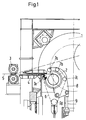
- 1 denotes the carousel reel, which has two reel mandrels 2 offset by 180 degrees, of which only one is shown.
- the belt 5 inserted by the driving roller set 3 through the threading device 4 is transported into the region of the reel mandrel 2 and is passed there between the reel mandrel and the toothed chain 6 partially wrapping around the reel mandrel 2.
- the toothed chain 6 is guided around toothed deflection wheels 7a to 7d, of which the deflection wheel 7e is driven.
- the deflection wheels 7a to 7c are arranged on a common lever 8 which can be pivoted away by pressure medium 9.
- the deflection wheel 7e remains stationary.
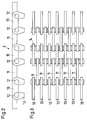
- the toothed chain 6 is shown in detail in the side view, it recognizably consists of the chain links 10, which is connected via links 11, which are bolted to the chain links 10 at 12.
- the chain links 10 are smooth on one side of the toothed chain 6 and with the tabs 11 designed flush, while on the opposite side the chain links 10 are toothed at 13. With these toothings 13, the toothed chain engages in the corresponding circumferentially toothed deflection wheels 7a to 7e, as will be described later.
- FIG. 3 shows a top view of a link plate assembly of a toothed chain according to the invention, the link plates 11 being recognizably arranged centrally between two chain links 10 and being kept at a distance by spacers 14 on the bolt 12.
- FIG. 4 shows a section through the toothed chain 6 according to the invention in the area of the deflection wheels 7e. These are held on the common shaft 15 at 16 so that they cannot rotate and are driven by the bevel gear 17 by a bevel gear 18 which is connected to a geared motor 19.
- the deflection wheels 7e are provided with a circumferential groove 20 and are also toothed at 21 on their circumference. While the teeth 13 of the chain 6 engage in the toothing 21, the tabs 11 are guided in the groove 20 of each deflection wheel 10e, so that a lateral displacement of the toothed chain 6 is prevented.
- the entrainment takes place via the teeth 21 of the deflection wheels 10e and the teeth 13 of the chain 6 at a speed which corresponds to the running-in speed of the band or the winding-up speed of the mandrel.
- the tape is shown at 5 in FIG. 4; the toothed chain can be seen to consist of 4 adjacent chain units lying on the belt 5, each chain unit being designed according to FIG. 3.
Landscapes
- Engineering & Computer Science (AREA)
- Mechanical Engineering (AREA)
- Devices For Conveying Motion By Means Of Endless Flexible Members (AREA)
- Storage Of Web-Like Or Filamentary Materials (AREA)
Applications Claiming Priority (2)
| Application Number | Priority Date | Filing Date | Title |
|---|---|---|---|
| DE4419377A DE4419377C2 (de) | 1994-05-27 | 1994-05-27 | Vorrichtung zum Anwickeln von bandförmigem Walzgut |
| DE4419377 | 1994-05-27 |
Publications (2)
| Publication Number | Publication Date |
|---|---|
| EP0707904A1 true EP0707904A1 (fr) | 1996-04-24 |
| EP0707904B1 EP0707904B1 (fr) | 1998-03-18 |
Family
ID=6519675
Family Applications (1)
| Application Number | Title | Priority Date | Filing Date |
|---|---|---|---|
| EP95250123A Expired - Lifetime EP0707904B1 (fr) | 1994-05-27 | 1995-05-23 | Dispositif pour enrouler des matières à laminer en forme de feuillard |
Country Status (2)
| Country | Link |
|---|---|
| EP (1) | EP0707904B1 (fr) |
| DE (2) | DE4419377C2 (fr) |
Cited By (4)
| Publication number | Priority date | Publication date | Assignee | Title |
|---|---|---|---|---|
| EP0897765A1 (fr) * | 1997-07-21 | 1999-02-24 | Kvaerner Technology & Research Limited | Enroulement et cisaillage de bandes métalliques |
| WO1999008815A1 (fr) * | 1997-08-15 | 1999-02-25 | Sms Schloemann-Siemag Aktiengesellschaft | Enrouleuse rotorique |
| DE102010025077A1 (de) | 2010-06-25 | 2011-12-29 | Sms Siemag Ag | Vorrichtung zum Aufwickeln eines Metallbandes |
| EP4670863A1 (fr) | 2024-06-26 | 2025-12-31 | SMS Group GmbH | Dispositif et procédé d'enroulement d'un produit laminé en forme de bande sur un mandrin ou un manchon d'un dispositif enrouleur |
Families Citing this family (2)
| Publication number | Priority date | Publication date | Assignee | Title |
|---|---|---|---|---|
| US6082659A (en) * | 1997-07-15 | 2000-07-04 | Kaiser Aluminum & Chemical Corp. | High speed transfer of strip in a continuous strip processing application |
| EP1384533B1 (fr) * | 1997-11-27 | 2007-07-18 | Mitsubishi Heavy Industries, Ltd. | Système à enrouler une bande |
Citations (3)
| Publication number | Priority date | Publication date | Assignee | Title |
|---|---|---|---|---|
| DE1248602B (de) | 1964-02-18 | 1967-08-31 | Spidem Ste Nle | Riemenumschlinger fuer einen Bandhaspel |
| DE1294320B (de) * | 1966-12-28 | 1969-05-08 | Masch U Werkzeugbau Gmbh | Riemenumschlinger |
| US4664329A (en) * | 1985-05-02 | 1987-05-12 | Essex Group, Inc. | Wire coiler |
-
1994
- 1994-05-27 DE DE4419377A patent/DE4419377C2/de not_active Expired - Fee Related
-
1995
- 1995-05-23 DE DE59501638T patent/DE59501638D1/de not_active Expired - Fee Related
- 1995-05-23 EP EP95250123A patent/EP0707904B1/fr not_active Expired - Lifetime
Patent Citations (3)
| Publication number | Priority date | Publication date | Assignee | Title |
|---|---|---|---|---|
| DE1248602B (de) | 1964-02-18 | 1967-08-31 | Spidem Ste Nle | Riemenumschlinger fuer einen Bandhaspel |
| DE1294320B (de) * | 1966-12-28 | 1969-05-08 | Masch U Werkzeugbau Gmbh | Riemenumschlinger |
| US4664329A (en) * | 1985-05-02 | 1987-05-12 | Essex Group, Inc. | Wire coiler |
Cited By (5)
| Publication number | Priority date | Publication date | Assignee | Title |
|---|---|---|---|---|
| EP0897765A1 (fr) * | 1997-07-21 | 1999-02-24 | Kvaerner Technology & Research Limited | Enroulement et cisaillage de bandes métalliques |
| WO1999008815A1 (fr) * | 1997-08-15 | 1999-02-25 | Sms Schloemann-Siemag Aktiengesellschaft | Enrouleuse rotorique |
| US6364242B1 (en) | 1997-08-15 | 2002-04-02 | Sms Schloemann-Siemag Aktiengesellschaft | Rotor winder |
| DE102010025077A1 (de) | 2010-06-25 | 2011-12-29 | Sms Siemag Ag | Vorrichtung zum Aufwickeln eines Metallbandes |
| EP4670863A1 (fr) | 2024-06-26 | 2025-12-31 | SMS Group GmbH | Dispositif et procédé d'enroulement d'un produit laminé en forme de bande sur un mandrin ou un manchon d'un dispositif enrouleur |
Also Published As
| Publication number | Publication date |
|---|---|
| EP0707904B1 (fr) | 1998-03-18 |
| DE59501638D1 (de) | 1998-04-23 |
| DE4419377A1 (de) | 1995-11-30 |
| DE4419377C2 (de) | 1996-04-25 |
Similar Documents
| Publication | Publication Date | Title |
|---|---|---|
| EP0540893B1 (fr) | Toronneuse pour câbles, notamment de grand diamètre à sens de câblage alterné | |
| DE2041686C3 (de) | Fordermagazin | |
| EP1003617B1 (fr) | Enrouleuse rotorique | |
| DE4419377C2 (de) | Vorrichtung zum Anwickeln von bandförmigem Walzgut | |
| EP0773074A1 (fr) | Accumulateur de bandes horizontal | |
| DE1237050B (de) | Kontinuierlich arbeitender Mehrtrommelhaspel fuer steifes Metallband | |
| DE2943770C2 (de) | Verfahren und Vorrichtung zur Herstellung eines Reifenwulstes aus Draht | |
| DE2220025A1 (de) | Band-Spreizvorrichtung | |
| EP0477498B1 (fr) | Dispositif d'enroulement de produits imprimés | |
| EP0088347B1 (fr) | Dispositif à chaînes de tirage et de freinage pour la stabilisation des tensions de bandes métalliques | |
| EP0275864B1 (fr) | Dispositif pour le traitement thermique d'un fil métallique en défilement continu | |
| DE2729646C2 (de) | Vorrichtung zum Aufwickeln von parallel angelieferten Bändern, insbesondere fotografischen Papierbändern | |
| DE3909403A1 (de) | Bandspeicher fuer einen kontinuierlichen betrieb von walzstrassen | |
| DE2111160B2 (de) | Vorrichtung zum foerdern von metallisierten baendern in einer folienmaterial bearbeitenden plattenpresse | |
| EP0881009A2 (fr) | Dispositif d'enroulement de bandes laminées minces et dispositif d'enroulement à la fin d'une installation de laminage en continu | |
| CH657084A5 (de) | Rollabdeckung einer fuehrungsbahn fuer einen schlitten an einer werkzeugmaschine. | |
| DE2524763B2 (de) | Metallband fuer einen gewickelten bund und vorrichtung zur herstellung des metallbandes | |
| DE19540748C2 (de) | Blechlängsteilanlage mit Haupt- und Vorbremse | |
| DE3717295C2 (fr) | ||
| WO1999048629A1 (fr) | Bobineuse pour une bande metallique mince | |
| DE527389C (de) | Bandwalzwerk | |
| DE19836159A1 (de) | Rotorhaspel | |
| DE679431C (de) | Wickelvorrichtung fuer bandartiges Walzgut | |
| DE1760496A1 (de) | Schneidvorrichtung mit Traeger fuer einen flexiblen Arbeitstisch | |
| DE3441434A1 (de) | Ziehdrahthaspelanordnung mit, einen doppeltrommelblock bildender obertrommel und untertrommel |
Legal Events
| Date | Code | Title | Description |
|---|---|---|---|
| PUAI | Public reference made under article 153(3) epc to a published international application that has entered the european phase |
Free format text: ORIGINAL CODE: 0009012 |
|
| AK | Designated contracting states |
Kind code of ref document: A1 Designated state(s): DE FR GB IT |
|
| 17P | Request for examination filed |
Effective date: 19960528 |
|
| GRAG | Despatch of communication of intention to grant |
Free format text: ORIGINAL CODE: EPIDOS AGRA |
|
| GRAG | Despatch of communication of intention to grant |
Free format text: ORIGINAL CODE: EPIDOS AGRA |
|
| GRAH | Despatch of communication of intention to grant a patent |
Free format text: ORIGINAL CODE: EPIDOS IGRA |
|
| 17Q | First examination report despatched |
Effective date: 19970818 |
|
| GRAH | Despatch of communication of intention to grant a patent |
Free format text: ORIGINAL CODE: EPIDOS IGRA |
|
| GRAA | (expected) grant |
Free format text: ORIGINAL CODE: 0009210 |
|
| AK | Designated contracting states |
Kind code of ref document: B1 Designated state(s): DE FR GB IT |
|
| ET | Fr: translation filed | ||
| PGFP | Annual fee paid to national office [announced via postgrant information from national office to epo] |
Ref country code: FR Payment date: 19980417 Year of fee payment: 4 |
|
| REF | Corresponds to: |
Ref document number: 59501638 Country of ref document: DE Date of ref document: 19980423 |
|
| ITF | It: translation for a ep patent filed | ||
| PGFP | Annual fee paid to national office [announced via postgrant information from national office to epo] |
Ref country code: DE Payment date: 19980622 Year of fee payment: 4 |
|
| GBT | Gb: translation of ep patent filed (gb section 77(6)(a)/1977) |
Effective date: 19980602 |
|
| PLBE | No opposition filed within time limit |
Free format text: ORIGINAL CODE: 0009261 |
|
| STAA | Information on the status of an ep patent application or granted ep patent |
Free format text: STATUS: NO OPPOSITION FILED WITHIN TIME LIMIT |
|
| 26N | No opposition filed | ||
| PG25 | Lapsed in a contracting state [announced via postgrant information from national office to epo] |
Ref country code: GB Free format text: LAPSE BECAUSE OF NON-PAYMENT OF DUE FEES Effective date: 19990523 |
|
| GBPC | Gb: european patent ceased through non-payment of renewal fee |
Effective date: 19990523 |
|
| PG25 | Lapsed in a contracting state [announced via postgrant information from national office to epo] |
Ref country code: FR Free format text: LAPSE BECAUSE OF NON-PAYMENT OF DUE FEES Effective date: 20000131 |
|
| PG25 | Lapsed in a contracting state [announced via postgrant information from national office to epo] |
Ref country code: DE Free format text: LAPSE BECAUSE OF NON-PAYMENT OF DUE FEES Effective date: 20000301 |
|
| REG | Reference to a national code |
Ref country code: FR Ref legal event code: ST |
|
| PG25 | Lapsed in a contracting state [announced via postgrant information from national office to epo] |
Ref country code: IT Free format text: LAPSE BECAUSE OF NON-PAYMENT OF DUE FEES;WARNING: LAPSES OF ITALIAN PATENTS WITH EFFECTIVE DATE BEFORE 2007 MAY HAVE OCCURRED AT ANY TIME BEFORE 2007. THE CORRECT EFFECTIVE DATE MAY BE DIFFERENT FROM THE ONE RECORDED. Effective date: 20050523 |