EP0707904B1 - Dispositif pour enrouler des matières à laminer en forme de feuillard - Google Patents
Dispositif pour enrouler des matières à laminer en forme de feuillard Download PDFInfo
- Publication number
- EP0707904B1 EP0707904B1 EP95250123A EP95250123A EP0707904B1 EP 0707904 B1 EP0707904 B1 EP 0707904B1 EP 95250123 A EP95250123 A EP 95250123A EP 95250123 A EP95250123 A EP 95250123A EP 0707904 B1 EP0707904 B1 EP 0707904B1
- Authority
- EP
- European Patent Office
- Prior art keywords
- chain
- toothed
- winding
- strip
- deflecting wheels
- Prior art date
- Legal status (The legal status is an assumption and is not a legal conclusion. Google has not performed a legal analysis and makes no representation as to the accuracy of the status listed.)
- Expired - Lifetime
Links
Images


Classifications
-
- B—PERFORMING OPERATIONS; TRANSPORTING
- B65—CONVEYING; PACKING; STORING; HANDLING THIN OR FILAMENTARY MATERIAL
- B65H—HANDLING THIN OR FILAMENTARY MATERIAL, e.g. SHEETS, WEBS, CABLES
- B65H19/00—Changing the web roll
- B65H19/22—Changing the web roll in winding mechanisms or in connection with winding operations
- B65H19/28—Attaching the leading end of the web to the replacement web-roll core or spindle
-
- B—PERFORMING OPERATIONS; TRANSPORTING
- B21—MECHANICAL METAL-WORKING WITHOUT ESSENTIALLY REMOVING MATERIAL; PUNCHING METAL
- B21C—MANUFACTURE OF METAL SHEETS, WIRE, RODS, TUBES, PROFILES OR LIKE SEMI-MANUFACTURED PRODUCTS OTHERWISE THAN BY ROLLING; AUXILIARY OPERATIONS USED IN CONNECTION WITH METAL-WORKING WITHOUT ESSENTIALLY REMOVING MATERIAL
- B21C47/00—Winding-up, coiling or winding-off metal wire, metal band or other flexible metal material characterised by features relevant to metal processing only
- B21C47/02—Winding-up or coiling
- B21C47/04—Winding-up or coiling on or in reels or drums, without using a moving guide
- B21C47/06—Winding-up or coiling on or in reels or drums, without using a moving guide with loaded rollers, bolts, or equivalent means holding the material on the reel or drum
- B21C47/066—Winding-up or coiling on or in reels or drums, without using a moving guide with loaded rollers, bolts, or equivalent means holding the material on the reel or drum with belt wrappers only
Definitions
- the invention relates to a device for winding strip-shaped rolling stock on the mandrel of a reel, in which the first turns by means of one of the turns looping tooth chain, endlessly guided over deflection wheels are held, the deflection wheels with one of the toothed chain corresponding peripheral teeth are provided and at least part of the deflection wheels is driven.
- Strip casting process wins the winding of hot strips, for example, for temporary storage, more and more meaning.
- a carousel reel is preferred used because these reelers with great Operational safety can be operated; because leading the beginning of the strip to the winding mandrel is largely trouble-free reachable.
- winding the strip-shaped rolling stock onto the Reel mandrels pay special attention to the winding of the the first two to three turns, which are non-slip on the Thorn should rest.
- Belt winders are known for winding cold strip which an endless belt around the pulleys Haspeldorn and thus the turns on it partially wraps around.
- the belt has no drive and is through Frictional contact carried by the mandrel.
- Belts and pulleys are arranged on swing-away frame parts, which can be rolled up swung in and swung away after unwinding can.
- metal cord belts are preferred used, these are rubber or rubber belts with particularly abrasion-resistant surface, the inside with highly elastic steel cables are reinforced.
- Such straps are operational up to temperatures of 200 degrees C and for low Winding speeds of approx. 1.5 m / sec.
- a sling known for a cold strip reel which is in the manner of a caterpillar track pressure body rotatably mounted on at least one toothed chain has, which extend transversely to the tooth chain.
- the Pressure hulls are covered with an elastic material.
- the well-known belt sling is unsuitable for hot strip because the pressure pieces are not temperature resistant and a discharge from tinder.
- the well-known facility is therefore only suitable for cold strip.
- wire link strips made of round or flat wire, made of chrome-nickel steel are made. These link bands wear out because of the high mechanical load on the deflections, in particular at high speeds very quickly, whereby Winding speeds of approx. 0.5 m / sec. the upper limit represent.
- the temperature load of such wire link belts should not exceed 400 degrees C.
- All of the winding devices described above are only for relatively low winding speeds and limited Suitable temperature ranges and have, especially for do not enforce the rough operation in hot strip rolling mills can.
- the service life of the known pressing devices is extremely low and is given as 1 to 2 weeks.
- Wire link belts are their pollution by the accumulating Tinder. This requires extensive maintenance of the link belts, if the service life specified above is to be achieved. Also the wire link belts are sensitive when using belts different widths must be rolled; because they are not suitable for absorbing lateral forces. Preferably should when using these wire link belts, the bandwidth is larger than the belt width, which is a frequent change of belts required when rolling strips of different widths makes. Also the jerky acceleration on contact with the mandrel for the life of the wire link belts disadvantageous.
- the invention proposes that the tooth chain with a loosened tab link with several arranged side by side and by spacers spaced chain parts that one form a common strand, with the chain links on the the side facing to be wound smooth and on the the side facing the deflection wheels are toothed.
- Such a tooth chain for example made of heat-treated Chain steel, is highly heat-resistant and wear-resistant.
- the smooth side of the tooth chain protects the belt surface, whereby by driving the idler wheels one with the incoming one Band or the mandrel synchronous speed is adjustable. As a result, relative movements between the tooth chain and the belt surface, which could lead to wear avoided.
- the back of the tooth chain i.e. the one to be wrapped up
- the side facing the belt is almost rigid, but can be moved over the large mandrel diameter of the coiler mandrel can be bent well. In the opposite direction, the tooth chain is easy to turn, so that it can be guided over the toothed deflection wheels.
- the proposed tooth chain is for speeds up to 6 m / sec.
- the tooth chain according to the invention increases the life of the Winding device essential, and that for about 2 years.
- 1 denotes the carousel reel, the two Has reel mandrels 2 offset by 180 degrees, of which only one is shown.
- the from the driving roller set 3 through the Threading device 4 inserted band 5 is in the area of the coiler mandrel 2 transported and there between the coiler mandrel and the tooth chain partially wrapping around the reel mandrel 2 6 headed.
- the toothed chain 6 is around toothed deflection wheels 7a to 7d, of which the deflection wheel 7e is driven.
- the deflection wheels 7a to 7c are on a common lever 8 arranged, the pressure medium-operated 9 is pivoted away.
- the Deflection wheel 7e remains stationary.
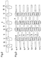
- the tooth chain 6 is cut out in the Side view shown, it consists recognizably of the Chain links 10, the plates 11, the chain links 10 are bolted at 12, is connected.
- the chain links 10 are smooth on one side of the tooth chain 6 and with the tabs 11 designed flush while on the opposite Page the chain links 10 are toothed at 13. With these Toothings 13 engage the toothed chain in the corresponding circumferentially toothed deflection wheels 7a to 7e, as later is described.
- FIG. 3 shows a top view of a flap bandage Tooth chain according to the invention, with the tabs being recognizable in each case 11 are arranged centrally between two chain links 10 and held at a distance by spacers 14 on the bolt 12 are.
- Figure 4 shows a section through the tooth chain according to the invention 6 in the area of the deflection wheels 7e. These are on the common shaft 15 held at 16 and torsion via the spur gear 17 from a bevel gear 18, which is connected to a geared motor 19, driven.
- the deflection wheels 7e are provided with a circumferential groove 20 and also toothed at 21 at its circumference. While the teeth 13 of the chain 6 engage in the toothing 21, the Tabs 11 in the groove 20 of each guide wheel 10e, so that a lateral offset of the tooth chain 6 is prevented.
- the entrainment takes place via the teeth 21 of the deflection wheels 10e and the teeth 13 of the chain 6 at a speed that the infeed speed of the belt or Winding speed of the mandrel corresponds.
- the tape is shown in Figure 4 at 5; the tooth chain is recognizable out of 4 adjacent to band 5 Chain units, each chain unit according to Figure 3 is executed.
Landscapes
- Engineering & Computer Science (AREA)
- Mechanical Engineering (AREA)
- Devices For Conveying Motion By Means Of Endless Flexible Members (AREA)
- Storage Of Web-Like Or Filamentary Materials (AREA)
Claims (2)
- Dispositif pour enrouler de la matière laminée sous forme de feuillard sur le mandrin (2) d'un treuil, dans lequel les premières spires sont maintenues au moyen d'une chaíne dentée (6) entourant partiellement les spires et guidée sans fin par l'intermédiaire de roues de renvoi, les roues de renvoi (7a-e) étant munies d'une denture périphérique correspondant à la chaíne dentée et au moins une partie des roues de renvoi étant entraínée, caractérisé en ce que la chaíne dentée (6) est constituée d'un assemblage de maillons détendu comportant plusieurs unités de chaíne agencées l'une à côté de l'autre et maintenues à distance par des disques d'écartement (14), lesquelles forment un brin commun, dont les maillons (10) sont réalisés, sur le côté en regard du feuillard (5) à enrouler, de façon lisse et, sur le côté en regard des roues de renvoi, de façon dentée (13).
- Dispositif selon la revendication 1,
caractérisé en ce que, pour le guidage latéral de la chaíne dentée, des maillons individuels (11) s'engagent dans des gorges périphériques (20) des roues de renvoi (7a-e) dentées à la périphérie.
Applications Claiming Priority (2)
| Application Number | Priority Date | Filing Date | Title |
|---|---|---|---|
| DE4419377A DE4419377C2 (de) | 1994-05-27 | 1994-05-27 | Vorrichtung zum Anwickeln von bandförmigem Walzgut |
| DE4419377 | 1994-05-27 |
Publications (2)
| Publication Number | Publication Date |
|---|---|
| EP0707904A1 EP0707904A1 (fr) | 1996-04-24 |
| EP0707904B1 true EP0707904B1 (fr) | 1998-03-18 |
Family
ID=6519675
Family Applications (1)
| Application Number | Title | Priority Date | Filing Date |
|---|---|---|---|
| EP95250123A Expired - Lifetime EP0707904B1 (fr) | 1994-05-27 | 1995-05-23 | Dispositif pour enrouler des matières à laminer en forme de feuillard |
Country Status (2)
| Country | Link |
|---|---|
| EP (1) | EP0707904B1 (fr) |
| DE (2) | DE4419377C2 (fr) |
Families Citing this family (6)
| Publication number | Priority date | Publication date | Assignee | Title |
|---|---|---|---|---|
| US6082659A (en) * | 1997-07-15 | 2000-07-04 | Kaiser Aluminum & Chemical Corp. | High speed transfer of strip in a continuous strip processing application |
| GB9715358D0 (en) * | 1997-07-21 | 1997-09-24 | Kvaerner Clecim Cont Casting | Method of shearing and guiding metal strip and apparatus therefor |
| DE29825030U1 (de) | 1997-08-15 | 2004-06-17 | Sms Demag Ag | Rotorhaspel |
| EP1384533B1 (fr) * | 1997-11-27 | 2007-07-18 | Mitsubishi Heavy Industries, Ltd. | Système à enrouler une bande |
| DE102010025077A1 (de) | 2010-06-25 | 2011-12-29 | Sms Siemag Ag | Vorrichtung zum Aufwickeln eines Metallbandes |
| DE102024205962A1 (de) | 2024-06-26 | 2026-02-19 | Sms Group Gmbh | Vorrichtung und Verfahren zum Anwickeln von bandförmigem Walzgut auf einem Dorn oder einer Hülse einer Haspeleinrichtung |
Family Cites Families (3)
| Publication number | Priority date | Publication date | Assignee | Title |
|---|---|---|---|---|
| FR1394178A (fr) * | 1964-02-18 | 1965-04-02 | Spidem Ste Nle | Perfectionnements aux dispositifs amorceurs d'enroulement |
| DE1294320B (de) * | 1966-12-28 | 1969-05-08 | Masch U Werkzeugbau Gmbh | Riemenumschlinger |
| US4664329A (en) * | 1985-05-02 | 1987-05-12 | Essex Group, Inc. | Wire coiler |
-
1994
- 1994-05-27 DE DE4419377A patent/DE4419377C2/de not_active Expired - Fee Related
-
1995
- 1995-05-23 DE DE59501638T patent/DE59501638D1/de not_active Expired - Fee Related
- 1995-05-23 EP EP95250123A patent/EP0707904B1/fr not_active Expired - Lifetime
Also Published As
| Publication number | Publication date |
|---|---|
| DE59501638D1 (de) | 1998-04-23 |
| DE4419377A1 (de) | 1995-11-30 |
| DE4419377C2 (de) | 1996-04-25 |
| EP0707904A1 (fr) | 1996-04-24 |
Similar Documents
| Publication | Publication Date | Title |
|---|---|---|
| DE2018849C3 (de) | Rechenkühlbett mit nachgeschaltetem Abführrollgang | |
| EP0540893B1 (fr) | Toronneuse pour câbles, notamment de grand diamètre à sens de câblage alterné | |
| DE69817205T2 (de) | Vorrichtung zum aufwickeln von metallband | |
| EP0773074B1 (fr) | Accumulateur de bandes horizontal | |
| DE2041686C3 (de) | Fordermagazin | |
| DE4240654A1 (de) | Abzugsvorrichtung für langgestrecktes Gut | |
| DE4419377C2 (de) | Vorrichtung zum Anwickeln von bandförmigem Walzgut | |
| DE29825030U1 (de) | Rotorhaspel | |
| DE2133336A1 (de) | Verfahren zum gleichzeitigen Ziehen einer Anzahl von Draehten und Vorrichtung zur Ausfuehrung des Verfahrens | |
| EP0275864B1 (fr) | Dispositif pour le traitement thermique d'un fil métallique en défilement continu | |
| DE2729646C2 (de) | Vorrichtung zum Aufwickeln von parallel angelieferten Bändern, insbesondere fotografischen Papierbändern | |
| EP2718215B1 (fr) | Mécanisme de traction pour le transport de filaments | |
| EP0388708B1 (fr) | Accumulateur de bandes pour l'opération continue de lignes de laminage | |
| CH668761A5 (de) | Einrichtung zum aufwickeln eines kontinuierlich anfallenden schuppenstromes von biegsamen flaechengebilden zu einem wickel. | |
| DE3151618C2 (de) | Bandabdeckung einer Führungsbahn für einen Schlitten an einer Werkzeugmaschine | |
| DE2315306A1 (de) | Leitvorrichtung fuer ununterbrochen gegossene metallbaender | |
| DE2707044C2 (de) | Paraffiniereinrichtung | |
| DE2332888A1 (de) | Stranggiessanlage | |
| EP0881009A2 (fr) | Dispositif d'enroulement de bandes laminées minces et dispositif d'enroulement à la fin d'une installation de laminage en continu | |
| DE2917027A1 (de) | Verfahren und einrichtung zum foerdern von aufeinanderfolgenden heissen wicklungen | |
| WO1985005577A1 (fr) | Procede et dispositif pour laminer une bande de metal | |
| DE1221413B (de) | Seilwinde mit zwei Treibscheiben und einer Speichertrommel | |
| DE527389C (de) | Bandwalzwerk | |
| DE1760496A1 (de) | Schneidvorrichtung mit Traeger fuer einen flexiblen Arbeitstisch | |
| DE19836159A1 (de) | Rotorhaspel |
Legal Events
| Date | Code | Title | Description |
|---|---|---|---|
| PUAI | Public reference made under article 153(3) epc to a published international application that has entered the european phase |
Free format text: ORIGINAL CODE: 0009012 |
|
| AK | Designated contracting states |
Kind code of ref document: A1 Designated state(s): DE FR GB IT |
|
| 17P | Request for examination filed |
Effective date: 19960528 |
|
| GRAG | Despatch of communication of intention to grant |
Free format text: ORIGINAL CODE: EPIDOS AGRA |
|
| GRAG | Despatch of communication of intention to grant |
Free format text: ORIGINAL CODE: EPIDOS AGRA |
|
| GRAH | Despatch of communication of intention to grant a patent |
Free format text: ORIGINAL CODE: EPIDOS IGRA |
|
| 17Q | First examination report despatched |
Effective date: 19970818 |
|
| GRAH | Despatch of communication of intention to grant a patent |
Free format text: ORIGINAL CODE: EPIDOS IGRA |
|
| GRAA | (expected) grant |
Free format text: ORIGINAL CODE: 0009210 |
|
| AK | Designated contracting states |
Kind code of ref document: B1 Designated state(s): DE FR GB IT |
|
| ET | Fr: translation filed | ||
| PGFP | Annual fee paid to national office [announced via postgrant information from national office to epo] |
Ref country code: FR Payment date: 19980417 Year of fee payment: 4 |
|
| REF | Corresponds to: |
Ref document number: 59501638 Country of ref document: DE Date of ref document: 19980423 |
|
| ITF | It: translation for a ep patent filed | ||
| PGFP | Annual fee paid to national office [announced via postgrant information from national office to epo] |
Ref country code: DE Payment date: 19980622 Year of fee payment: 4 |
|
| GBT | Gb: translation of ep patent filed (gb section 77(6)(a)/1977) |
Effective date: 19980602 |
|
| PLBE | No opposition filed within time limit |
Free format text: ORIGINAL CODE: 0009261 |
|
| STAA | Information on the status of an ep patent application or granted ep patent |
Free format text: STATUS: NO OPPOSITION FILED WITHIN TIME LIMIT |
|
| 26N | No opposition filed | ||
| PG25 | Lapsed in a contracting state [announced via postgrant information from national office to epo] |
Ref country code: GB Free format text: LAPSE BECAUSE OF NON-PAYMENT OF DUE FEES Effective date: 19990523 |
|
| GBPC | Gb: european patent ceased through non-payment of renewal fee |
Effective date: 19990523 |
|
| PG25 | Lapsed in a contracting state [announced via postgrant information from national office to epo] |
Ref country code: FR Free format text: LAPSE BECAUSE OF NON-PAYMENT OF DUE FEES Effective date: 20000131 |
|
| PG25 | Lapsed in a contracting state [announced via postgrant information from national office to epo] |
Ref country code: DE Free format text: LAPSE BECAUSE OF NON-PAYMENT OF DUE FEES Effective date: 20000301 |
|
| REG | Reference to a national code |
Ref country code: FR Ref legal event code: ST |
|
| PG25 | Lapsed in a contracting state [announced via postgrant information from national office to epo] |
Ref country code: IT Free format text: LAPSE BECAUSE OF NON-PAYMENT OF DUE FEES;WARNING: LAPSES OF ITALIAN PATENTS WITH EFFECTIVE DATE BEFORE 2007 MAY HAVE OCCURRED AT ANY TIME BEFORE 2007. THE CORRECT EFFECTIVE DATE MAY BE DIFFERENT FROM THE ONE RECORDED. Effective date: 20050523 |