EP0708022B1 - Vorrichtung zum verschliessen von verpackungsbehältern - Google Patents
Vorrichtung zum verschliessen von verpackungsbehältern Download PDFInfo
- Publication number
- EP0708022B1 EP0708022B1 EP94921098A EP94921098A EP0708022B1 EP 0708022 B1 EP0708022 B1 EP 0708022B1 EP 94921098 A EP94921098 A EP 94921098A EP 94921098 A EP94921098 A EP 94921098A EP 0708022 B1 EP0708022 B1 EP 0708022B1
- Authority
- EP
- European Patent Office
- Prior art keywords
- horn
- ultrasonic vibration
- sealing
- fin portion
- tip
- Prior art date
- Legal status (The legal status is an assumption and is not a legal conclusion. Google has not performed a legal analysis and makes no representation as to the accuracy of the status listed.)
- Expired - Lifetime
Links
Images


Classifications
-
- B—PERFORMING OPERATIONS; TRANSPORTING
- B29—WORKING OF PLASTICS; WORKING OF SUBSTANCES IN A PLASTIC STATE IN GENERAL
- B29C—SHAPING OR JOINING OF PLASTICS; SHAPING OF MATERIAL IN A PLASTIC STATE, NOT OTHERWISE PROVIDED FOR; AFTER-TREATMENT OF THE SHAPED PRODUCTS, e.g. REPAIRING
- B29C66/00—General aspects of processes or apparatus for joining preformed parts
- B29C66/80—General aspects of machine operations or constructions and parts thereof
-
- B—PERFORMING OPERATIONS; TRANSPORTING
- B65—CONVEYING; PACKING; STORING; HANDLING THIN OR FILAMENTARY MATERIAL
- B65B—MACHINES, APPARATUS OR DEVICES FOR, OR METHODS OF, PACKAGING ARTICLES OR MATERIALS; UNPACKING
- B65B7/00—Closing containers or receptacles after filling
- B65B7/16—Closing semi-rigid or rigid containers or receptacles not deformed by, or not taking-up shape of, contents, e.g. boxes or cartons
-
- B—PERFORMING OPERATIONS; TRANSPORTING
- B29—WORKING OF PLASTICS; WORKING OF SUBSTANCES IN A PLASTIC STATE IN GENERAL
- B29C—SHAPING OR JOINING OF PLASTICS; SHAPING OF MATERIAL IN A PLASTIC STATE, NOT OTHERWISE PROVIDED FOR; AFTER-TREATMENT OF THE SHAPED PRODUCTS, e.g. REPAIRING
- B29C65/00—Joining or sealing of preformed parts, e.g. welding of plastics materials; Apparatus therefor
- B29C65/02—Joining or sealing of preformed parts, e.g. welding of plastics materials; Apparatus therefor by heating, with or without pressure
- B29C65/08—Joining or sealing of preformed parts, e.g. welding of plastics materials; Apparatus therefor by heating, with or without pressure using ultrasonic vibrations
-
- B—PERFORMING OPERATIONS; TRANSPORTING
- B29—WORKING OF PLASTICS; WORKING OF SUBSTANCES IN A PLASTIC STATE IN GENERAL
- B29C—SHAPING OR JOINING OF PLASTICS; SHAPING OF MATERIAL IN A PLASTIC STATE, NOT OTHERWISE PROVIDED FOR; AFTER-TREATMENT OF THE SHAPED PRODUCTS, e.g. REPAIRING
- B29C66/00—General aspects of processes or apparatus for joining preformed parts
- B29C66/004—Preventing sticking together, e.g. of some areas of the parts to be joined
-
- B—PERFORMING OPERATIONS; TRANSPORTING
- B29—WORKING OF PLASTICS; WORKING OF SUBSTANCES IN A PLASTIC STATE IN GENERAL
- B29C—SHAPING OR JOINING OF PLASTICS; SHAPING OF MATERIAL IN A PLASTIC STATE, NOT OTHERWISE PROVIDED FOR; AFTER-TREATMENT OF THE SHAPED PRODUCTS, e.g. REPAIRING
- B29C66/00—General aspects of processes or apparatus for joining preformed parts
- B29C66/01—General aspects dealing with the joint area or with the area to be joined
- B29C66/05—Particular design of joint configurations
- B29C66/10—Particular design of joint configurations particular design of the joint cross-sections
- B29C66/11—Joint cross-sections comprising a single joint-segment, i.e. one of the parts to be joined comprising a single joint-segment in the joint cross-section
- B29C66/112—Single lapped joints
- B29C66/1122—Single lap to lap joints, i.e. overlap joints
-
- B—PERFORMING OPERATIONS; TRANSPORTING
- B29—WORKING OF PLASTICS; WORKING OF SUBSTANCES IN A PLASTIC STATE IN GENERAL
- B29C—SHAPING OR JOINING OF PLASTICS; SHAPING OF MATERIAL IN A PLASTIC STATE, NOT OTHERWISE PROVIDED FOR; AFTER-TREATMENT OF THE SHAPED PRODUCTS, e.g. REPAIRING
- B29C66/00—General aspects of processes or apparatus for joining preformed parts
- B29C66/40—General aspects of joining substantially flat articles, e.g. plates, sheets or web-like materials; Making flat seams in tubular or hollow articles; Joining single elements to substantially flat surfaces
- B29C66/41—Joining substantially flat articles ; Making flat seams in tubular or hollow articles
- B29C66/43—Joining a relatively small portion of the surface of said articles
- B29C66/431—Joining the articles to themselves
- B29C66/4312—Joining the articles to themselves for making flat seams in tubular or hollow articles, e.g. transversal seams
- B29C66/43121—Closing the ends of tubular or hollow single articles, e.g. closing the ends of bags
- B29C66/43122—Closing the top of gable top containers
-
- B—PERFORMING OPERATIONS; TRANSPORTING
- B29—WORKING OF PLASTICS; WORKING OF SUBSTANCES IN A PLASTIC STATE IN GENERAL
- B29C—SHAPING OR JOINING OF PLASTICS; SHAPING OF MATERIAL IN A PLASTIC STATE, NOT OTHERWISE PROVIDED FOR; AFTER-TREATMENT OF THE SHAPED PRODUCTS, e.g. REPAIRING
- B29C66/00—General aspects of processes or apparatus for joining preformed parts
- B29C66/70—General aspects of processes or apparatus for joining preformed parts characterised by the composition, physical properties or the structure of the material of the parts to be joined; Joining with non-plastics material
- B29C66/72—General aspects of processes or apparatus for joining preformed parts characterised by the composition, physical properties or the structure of the material of the parts to be joined; Joining with non-plastics material characterised by the structure of the material of the parts to be joined
- B29C66/723—General aspects of processes or apparatus for joining preformed parts characterised by the composition, physical properties or the structure of the material of the parts to be joined; Joining with non-plastics material characterised by the structure of the material of the parts to be joined being multi-layered
- B29C66/7232—General aspects of processes or apparatus for joining preformed parts characterised by the composition, physical properties or the structure of the material of the parts to be joined; Joining with non-plastics material characterised by the structure of the material of the parts to be joined being multi-layered comprising a non-plastics layer
- B29C66/72327—General aspects of processes or apparatus for joining preformed parts characterised by the composition, physical properties or the structure of the material of the parts to be joined; Joining with non-plastics material characterised by the structure of the material of the parts to be joined being multi-layered comprising a non-plastics layer consisting of natural products or their composites, not provided for in B29C66/72321 - B29C66/72324
- B29C66/72328—Paper
-
- B—PERFORMING OPERATIONS; TRANSPORTING
- B29—WORKING OF PLASTICS; WORKING OF SUBSTANCES IN A PLASTIC STATE IN GENERAL
- B29C—SHAPING OR JOINING OF PLASTICS; SHAPING OF MATERIAL IN A PLASTIC STATE, NOT OTHERWISE PROVIDED FOR; AFTER-TREATMENT OF THE SHAPED PRODUCTS, e.g. REPAIRING
- B29C66/00—General aspects of processes or apparatus for joining preformed parts
- B29C66/70—General aspects of processes or apparatus for joining preformed parts characterised by the composition, physical properties or the structure of the material of the parts to be joined; Joining with non-plastics material
- B29C66/73—General aspects of processes or apparatus for joining preformed parts characterised by the composition, physical properties or the structure of the material of the parts to be joined; Joining with non-plastics material characterised by the intensive physical properties of the material of the parts to be joined, by the optical properties of the material of the parts to be joined, by the extensive physical properties of the parts to be joined, by the state of the material of the parts to be joined or by the material of the parts to be joined being a thermoplastic or a thermoset
- B29C66/739—General aspects of processes or apparatus for joining preformed parts characterised by the composition, physical properties or the structure of the material of the parts to be joined; Joining with non-plastics material characterised by the intensive physical properties of the material of the parts to be joined, by the optical properties of the material of the parts to be joined, by the extensive physical properties of the parts to be joined, by the state of the material of the parts to be joined or by the material of the parts to be joined being a thermoplastic or a thermoset characterised by the material of the parts to be joined being a thermoplastic or a thermoset
- B29C66/7394—General aspects of processes or apparatus for joining preformed parts characterised by the composition, physical properties or the structure of the material of the parts to be joined; Joining with non-plastics material characterised by the intensive physical properties of the material of the parts to be joined, by the optical properties of the material of the parts to be joined, by the extensive physical properties of the parts to be joined, by the state of the material of the parts to be joined or by the material of the parts to be joined being a thermoplastic or a thermoset characterised by the material of the parts to be joined being a thermoplastic or a thermoset characterised by the material of at least one of the parts being a thermoset
-
- B—PERFORMING OPERATIONS; TRANSPORTING
- B29—WORKING OF PLASTICS; WORKING OF SUBSTANCES IN A PLASTIC STATE IN GENERAL
- B29C—SHAPING OR JOINING OF PLASTICS; SHAPING OF MATERIAL IN A PLASTIC STATE, NOT OTHERWISE PROVIDED FOR; AFTER-TREATMENT OF THE SHAPED PRODUCTS, e.g. REPAIRING
- B29C66/00—General aspects of processes or apparatus for joining preformed parts
- B29C66/80—General aspects of machine operations or constructions and parts thereof
- B29C66/81—General aspects of the pressing elements, i.e. the elements applying pressure on the parts to be joined in the area to be joined, e.g. the welding jaws or clamps
- B29C66/814—General aspects of the pressing elements, i.e. the elements applying pressure on the parts to be joined in the area to be joined, e.g. the welding jaws or clamps characterised by the design of the pressing elements, e.g. of the welding jaws or clamps
- B29C66/8141—General aspects of the pressing elements, i.e. the elements applying pressure on the parts to be joined in the area to be joined, e.g. the welding jaws or clamps characterised by the design of the pressing elements, e.g. of the welding jaws or clamps characterised by the surface geometry of the part of the pressing elements, e.g. welding jaws or clamps, coming into contact with the parts to be joined
- B29C66/81427—General aspects of the pressing elements, i.e. the elements applying pressure on the parts to be joined in the area to be joined, e.g. the welding jaws or clamps characterised by the design of the pressing elements, e.g. of the welding jaws or clamps characterised by the surface geometry of the part of the pressing elements, e.g. welding jaws or clamps, coming into contact with the parts to be joined comprising a single ridge, e.g. for making a weakening line; comprising a single tooth
-
- B—PERFORMING OPERATIONS; TRANSPORTING
- B29—WORKING OF PLASTICS; WORKING OF SUBSTANCES IN A PLASTIC STATE IN GENERAL
- B29C—SHAPING OR JOINING OF PLASTICS; SHAPING OF MATERIAL IN A PLASTIC STATE, NOT OTHERWISE PROVIDED FOR; AFTER-TREATMENT OF THE SHAPED PRODUCTS, e.g. REPAIRING
- B29C66/00—General aspects of processes or apparatus for joining preformed parts
- B29C66/80—General aspects of machine operations or constructions and parts thereof
- B29C66/82—Pressure application arrangements, e.g. transmission or actuating mechanisms for joining tools or clamps
- B29C66/824—Actuating mechanisms
- B29C66/8242—Pneumatic or hydraulic drives
-
- B—PERFORMING OPERATIONS; TRANSPORTING
- B29—WORKING OF PLASTICS; WORKING OF SUBSTANCES IN A PLASTIC STATE IN GENERAL
- B29C—SHAPING OR JOINING OF PLASTICS; SHAPING OF MATERIAL IN A PLASTIC STATE, NOT OTHERWISE PROVIDED FOR; AFTER-TREATMENT OF THE SHAPED PRODUCTS, e.g. REPAIRING
- B29C66/00—General aspects of processes or apparatus for joining preformed parts
- B29C66/80—General aspects of machine operations or constructions and parts thereof
- B29C66/83—General aspects of machine operations or constructions and parts thereof characterised by the movement of the joining or pressing tools
- B29C66/832—Reciprocating joining or pressing tools
- B29C66/8322—Joining or pressing tools reciprocating along one axis
-
- B—PERFORMING OPERATIONS; TRANSPORTING
- B65—CONVEYING; PACKING; STORING; HANDLING THIN OR FILAMENTARY MATERIAL
- B65B—MACHINES, APPARATUS OR DEVICES FOR, OR METHODS OF, PACKAGING ARTICLES OR MATERIALS; UNPACKING
- B65B51/00—Devices for, or methods of, sealing or securing package folds or closures; Devices for gathering or twisting wrappers, or necks of bags
- B65B51/10—Applying or generating heat or pressure or combinations thereof
- B65B51/22—Applying or generating heat or pressure or combinations thereof by friction or ultrasonic or high-frequency electrical means
- B65B51/225—Applying or generating heat or pressure or combinations thereof by friction or ultrasonic or high-frequency electrical means by ultrasonic welding
-
- B—PERFORMING OPERATIONS; TRANSPORTING
- B29—WORKING OF PLASTICS; WORKING OF SUBSTANCES IN A PLASTIC STATE IN GENERAL
- B29C—SHAPING OR JOINING OF PLASTICS; SHAPING OF MATERIAL IN A PLASTIC STATE, NOT OTHERWISE PROVIDED FOR; AFTER-TREATMENT OF THE SHAPED PRODUCTS, e.g. REPAIRING
- B29C66/00—General aspects of processes or apparatus for joining preformed parts
- B29C66/80—General aspects of machine operations or constructions and parts thereof
- B29C66/81—General aspects of the pressing elements, i.e. the elements applying pressure on the parts to be joined in the area to be joined, e.g. the welding jaws or clamps
- B29C66/814—General aspects of the pressing elements, i.e. the elements applying pressure on the parts to be joined in the area to be joined, e.g. the welding jaws or clamps characterised by the design of the pressing elements, e.g. of the welding jaws or clamps
- B29C66/8141—General aspects of the pressing elements, i.e. the elements applying pressure on the parts to be joined in the area to be joined, e.g. the welding jaws or clamps characterised by the design of the pressing elements, e.g. of the welding jaws or clamps characterised by the surface geometry of the part of the pressing elements, e.g. welding jaws or clamps, coming into contact with the parts to be joined
- B29C66/81411—General aspects of the pressing elements, i.e. the elements applying pressure on the parts to be joined in the area to be joined, e.g. the welding jaws or clamps characterised by the design of the pressing elements, e.g. of the welding jaws or clamps characterised by the surface geometry of the part of the pressing elements, e.g. welding jaws or clamps, coming into contact with the parts to be joined characterised by its cross-section, e.g. transversal or longitudinal, being non-flat
- B29C66/81421—General aspects of the pressing elements, i.e. the elements applying pressure on the parts to be joined in the area to be joined, e.g. the welding jaws or clamps characterised by the design of the pressing elements, e.g. of the welding jaws or clamps characterised by the surface geometry of the part of the pressing elements, e.g. welding jaws or clamps, coming into contact with the parts to be joined characterised by its cross-section, e.g. transversal or longitudinal, being non-flat being convex or concave
- B29C66/81422—General aspects of the pressing elements, i.e. the elements applying pressure on the parts to be joined in the area to be joined, e.g. the welding jaws or clamps characterised by the design of the pressing elements, e.g. of the welding jaws or clamps characterised by the surface geometry of the part of the pressing elements, e.g. welding jaws or clamps, coming into contact with the parts to be joined characterised by its cross-section, e.g. transversal or longitudinal, being non-flat being convex or concave being convex
-
- B—PERFORMING OPERATIONS; TRANSPORTING
- B29—WORKING OF PLASTICS; WORKING OF SUBSTANCES IN A PLASTIC STATE IN GENERAL
- B29C—SHAPING OR JOINING OF PLASTICS; SHAPING OF MATERIAL IN A PLASTIC STATE, NOT OTHERWISE PROVIDED FOR; AFTER-TREATMENT OF THE SHAPED PRODUCTS, e.g. REPAIRING
- B29C66/00—General aspects of processes or apparatus for joining preformed parts
- B29C66/90—Measuring or controlling the joining process
- B29C66/92—Measuring or controlling the joining process by measuring or controlling the pressure, the force, the mechanical power or the displacement of the joining tools
-
- B—PERFORMING OPERATIONS; TRANSPORTING
- B29—WORKING OF PLASTICS; WORKING OF SUBSTANCES IN A PLASTIC STATE IN GENERAL
- B29L—INDEXING SCHEME ASSOCIATED WITH SUBCLASS B29C, RELATING TO PARTICULAR ARTICLES
- B29L2031/00—Other particular articles
- B29L2031/712—Containers; Packaging elements or accessories, Packages
- B29L2031/7162—Boxes, cartons, cases
- B29L2031/7166—Cartons of the fruit juice or milk type, i.e. containers of polygonal cross sections formed by folding blanks into a tubular body with end-closing or contents-supporting elements, e.g. gable type containers
-
- Y—GENERAL TAGGING OF NEW TECHNOLOGICAL DEVELOPMENTS; GENERAL TAGGING OF CROSS-SECTIONAL TECHNOLOGIES SPANNING OVER SEVERAL SECTIONS OF THE IPC; TECHNICAL SUBJECTS COVERED BY FORMER USPC CROSS-REFERENCE ART COLLECTIONS [XRACs] AND DIGESTS
- Y10—TECHNICAL SUBJECTS COVERED BY FORMER USPC
- Y10S—TECHNICAL SUBJECTS COVERED BY FORMER USPC CROSS-REFERENCE ART COLLECTIONS [XRACs] AND DIGESTS
- Y10S53/00—Package making
- Y10S53/02—High frequency electric sealing
Definitions
- the present invention relates to a sealing apparatus for packaging containers.
- gable-top type packaging container which has a roof-shaped top.
- a carton blank is first formed into a square tubular carton by a filling machine, and a spout is then attached to the carton.
- the bottom end of the carton is then sealed by mandrels to make a bottom.
- a liquid food is then placed in the carton having a bottom through the top opening thereof.
- the top portion of the carton is folded along predetermined pleat lines, and is then sealed.
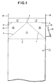
- FIG. 1 is a side view of a square tubular carton which is used for forming a gable-top type packaging container
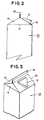
- FIG. 2 is a side view of a packaging container
- FIG. 3 is a perspective view of a packaging container.
- numeral 11 denotes a square tubular carton made of a packaging material
- numeral 12 denotes a spout attached to a predetermined position of the carton 11.
- a plurality of pleat lines a through f are formed on the square tubular carton 11.
- the carton is folded along the pleat lines a through f to form a triangular panel 15, folding panels 16, inner sealing fins 17, outer sealing fins 18, and slanting roof panels 19.
- each pair of sealant layers of the inner sealing fins 17 facing each other is fused while each pair of sealant layers of the outer sealing fins 18 facing each other is also fused, thereby forming a packaging container 13.
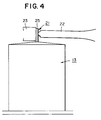
- FIG. 4 is a diagram showing the operation of a sealing apparatus for packaging containers in which ultrasonic waves are utilized.
- numeral 13 denotes a packaging container
- numeral 21 denotes a sealing fin portion composed of the aforementioned inner sealing fins 17 and outer sealing fins 18 (see Fig. 1).
- Numeral 22 denotes a horn of an ultrasonic sealing head while numeral 23 denotes an anvil disposed in front of the horn 22.
- the sealing fin portion 21 When the horn 22 is advanced to its advanced position, the sealing fin portion 21 is pressed by the horn 22 toward the anvil 23 while receiving ultrasonic vibration from the horn 22, so that each pair of opposing sealant layers is fused and joined.
- sealant layers can be directly heated by ultrasonic vibration without heating the paper substrate. This facilitates adjustment of the heating conditions, and increases stability of joining.
- the edge portion 25 of the sealing fin portion 21 vibrates. Since an end surface of the paper substrate is exposed to the outside at the edge portion 25, dust is produced from the end surface of the paper substrate, and the dust flies around. Therefore, a problem exists that the dust is mixed into a liquid food being filled in the packaging container.
- An object of the present invention is to solve the above-mentioned problems in the conventional sealing apparatus for packaging containers and to provide an improved sealing apparatus for packaging containers which does not produce dust from an end surface of a paper substrate, which dust would otherwise fly around.
- a sealing apparatus for packaging containers according to the present Invention can be applied to production of a gable-top type packaging container in which a square tubular carton is folded along pleat lines, and each pair of sealant layers of a sealing fin portion facing each other is fused for sealing, whereby the gable-top type packaging container is formed.
- the sealing apparatus includes an anvil for supporting a sealing fin portion, a horn composed of a columnar portion and a converging portion, and means for pressing the sealing fin portion against the anvil through the tip of the horn and for transmitting ultrasonic vibration to the sealing fin portion.
- the horn transmits the ultrasonic vibration to the packaging material, thereby fusing each pair of sealant layers of the sealing fin portion to effect sealing.
- the apparatus is characterized in that there is provided ultrasonic vibration absorbing means disposed such that, in use, it is located between the tip of the horn and the free edge portion of the sealing fin portion and in contact with said sealing fin portion for absorbing ultrasonic vibration.
- the sealing fin portion When ultrasonic vibration is transmitted to the sealing fin portion, the sealing fin portion is excited to transmit the vibration toward the edge portion. However, since the vibration is absorbed by the ultrasonic vibration absorbing means, the vibration does not reach the edge portion. Accordingly, it is possible to prevent the generation of dust from an end surface of the paper substrate which is exposed to the outside at the edge portion of the sealing fin portion.
- the ultrasonic vibration absorbing means is a projection which is formed on the anvil for holding a packaging material in cooperation with the tip of the horn. In this case, since ultrasonic vibration is absorbed by the anvil through the projection, the ultrasonic vibration is not transmitted to the edge portion of the sealing fin portion.
- the ultrasonic vibration absorbing means is an outside pusher which is disposed along the tip portion of the horn and which is pressed against the sealing fin portion.
- the aforementioned outside pusher has a tubular portion surrounding the horn, and a support member which inwardly extends from the tubular portion for supporting the horn.
- the tip of the support member contacts a portion corresponding to a node of the standing wave of ultrasonic vibration transmitted to the horn.
- the ultrasonic vibration transmitted to the horn is prevented from being transmitted to the outside pusher via the support member.
- FIG. 1 is a side view of a square tubular carton which is used for forming a gable-top type packaging container
- FIG. 2 is a side view of a packaging container
- FIG. 3 is a perspective view of a packaging container
- FIG. 4 is a diagram showing a sealing operation for packaging containers in which ultrasonic waves are utilized
- FIG. 5 is a schematic view of a sealing apparatus for packaging containers according to a first embodiment of the present invention
- FIG. 6 is a sectional view taken along line X-X in FIG. 5
- FIG. 7 is a schematic view of a main portion of a sealing apparatus for packaging containers according to a second embodiment of the present invention
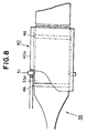
- FIG. 8 is a schematic view of a main portion of a sealing apparatus for packaging containers according to a third embodiment of the present invention.
- FIG. 5 is a schematic view of a sealing apparatus for packaging containers according to a first embodiment of the present invention
- FIG. 6 is a sectional view taken along line X-X in FIG. 5.
- numeral 13 denotes a packaging container made of a packaging material
- numeral 21 denotes a sealing fin portion composed of inner sealing fins 17 (see FIG. 1) and outer sealing fins 18.
- the packaging material includes a paper substrate, and a polyethylene layer functioning as a sealant layer is formed on both of the surfaces of the paper substrate, one of which will become an inside surface of a packaging container (hereinafter referred to as "container inner surface”) and the other of which will become an outside surface of the packaging container (hereinafter referred to as "container outer surface").
- Numeral 31 denotes a sealer which is supported by a sealing apparatus body 33 through a bracket 32.
- the sealing apparatus body 33 is connected to an unillustrated air cylinder or the like so as to be advanced and retracted along a direction indicated by an arrow A by the air cylinder or the like.
- the ultrasonic sealer 31 is composed of a horn 35, a converter 36 and a booster 37. Ultrasonic generated by the converter 36 is amplified by the booster 37, and the energy of the amplified ultrasonic waves is converged to the tip 35c.
- the horn 35 is composed of a rear square columnar portion 35a and a front converging portion 35b. The converging portion 35b is gradually flattened as approaching the tip 35c, and the tip 35c extends in a horizontal direction (in a direction perpendicular to the drawing) along the outer sealing fins 18.
- an anvil 23 is disposed in front of the horn 35.
- the sealing fin portion 21 is pressed by the horn 35 toward the anvil 23 so that ultrasonic vibration is transmitted to the sealing fin portion 21.
- each pair of opposing sealant layers is fused and joined.
- an outside pusher 40 functioning as an ultrasonic vibration absorbing means is disposed along the horn 35.
- the outside pusher 40 is composed of a square tubular portion 40a and a flat portion 40b disposed along the converging portion 35b, and the tip 40c of the outside pusher 40 contacts the sealing fine portion 21 at a position between the tip 35c of the horn 35 and the edge portion 25 of the sealing fine portion 21, and extends in a horizontal direction (in a direction perpendicular to the drawing) along the tip 35c.
- the tip 40c of the outside pusher 40 presses the sealing fin portion 21 against the anvil 23 in cooperation with the tip 35c of the horn 35.
- the sealing fin portion 21 When the ultrasonic sealer 31 is operated and ultrasonic vibration is then transmitted to the sealing fin portion 21, the sealing fin portion 21 is excited to transmit the vibration toward the edge portion 25. However, since the sealing fin portion 21 is pressed against the anvil 23 by the outside pusher 40, the vibration is absorbed by the outside pusher 40 so that the vibration does not reach the edge portion 25.
- the edge portion 25 is prevented from vibrating. Accordingly, it is possible to prevent the generation of dust from an end surface of the paper substrate which is exposed to the outside at the edge portion 25 of the sealing fin portion 21.
- a pair of elastic rings 46 are interposed between the square columnar portion 35a and the square tubular portion 40a, so that ultrasonic vibration in the horn 35 is prevented from being transmitted to the outside pusher 40.
- FIG. 7 is a schematic view of a main portion of a sealing apparatus for packaging containers according to the second embodiment of the present invention.
- numeral 13 denotes a packaging container
- numeral 21 denotes a sealing fin portion
- numeral 35 denotes a horn
- numeral 50 denotes an anvil disposed in front of the horn 35.
- an elongated projection 50a functioning as an ultrasonic vibration absorbing means is formed on a surface of the anvil 50 facing to the horn 35.
- the projection 50a extends in a horizontal direction (in a direction perpendicular to the drawing) at a position between the tip 35c of the horn 35 and the edge portion 25. Accordingly, the sealing fin portion 21 is held between the projection 50a and the tip 35c, when the sealing fin portion 21 is pressed against the anvil 50 by the horn 35 located in its advanced position.
- the sealing fin portion 21 When the ultrasonic sealer 31 (see FIG. 5) is operated and ultrasonic vibration is transmitted to the sealing fin portion 21, the sealing fin portion 21 is excited to transmit the vibration toward the edge portion 25. However, since the sealing fin portion 21 is held between the projection 50a and the tip 35c, the ultrasonic vibration is absorbed by the anvil 50 through the projection 50a so that the vibration does not reach the edge portion 25.
- the edge portion 25 is prevented from vibrating. Accordingly, it is possible to prevent the generation of dust from an end surface of the paper substrate which is exposed to the outside at the edge portion 25 of the sealing fin portion 21.
- FIG. 8 is a schematic view of a main portion of a sealing apparatus for packaging containers according to the third embodiment of the present invention.
- numeral 35 denotes a horn
- numeral 40 denotes an outside pusher disposed along the horn 35, acting as an ultrasonic vibration absorbing means.
- the outside pusher 40 has a square tubular portion 40a surrounding the square columnar portion 35a of the horn 35.
- a pair of elastic rings 46 are interposed between the square columnar portion 35a and the square tubular portion 40a, so that ultrasonic vibration in the horn 35 is prevented from being transmitted to the outside pusher 40.
- a support member 51 is fixed to the square tubular portion 40a and inwardly extends so that the tip of the support member 51 contacts the square columnar portion 35a.
- the position at which the tip of the support member 51 contacts the square columnar portion 35a is selected to correspond to a node of the standing wave of ultrasonic vibration transmitted to the horn 35. Since the outside pusher 40 supports the horn 35 through the support member 51, the bracket 32 shown in FIG. 5 can be eliminated.
- the sealing apparatus for packaging containers according to the present invention can be applied to a device for manufacturing a gable-top type packaging container.
Landscapes
- Engineering & Computer Science (AREA)
- Mechanical Engineering (AREA)
- Physics & Mathematics (AREA)
- Fluid Mechanics (AREA)
- Chemical & Material Sciences (AREA)
- Composite Materials (AREA)
- Package Closures (AREA)
- Closing Of Containers (AREA)
- Auxiliary Devices For And Details Of Packaging Control (AREA)
- Supplying Of Containers To The Packaging Station (AREA)
- Basic Packing Technique (AREA)
- Cartons (AREA)
- Containers And Plastic Fillers For Packaging (AREA)
Claims (4)
- Versiegelungsvorrichtung für Verpackungsbehälter, bei der ein viereckiger, rohrförmiger Karton (13) längs Falzlinien gefaltet wird und jedes Paar von einander zugewandten Versiegelungsschichten eines Versiegelungsrippenabschnitts (21) zur Versiegelung miteinander verschmolzen werden, um einen Verpackungsbehälter vom Typ mit giebelförmigem Oberteil zu bilden, wobei die Versiegelungsvorrichtung folgendes aufweist:(a) einen Amboß (23, 50) zum Halten des Versiegelungsrippenabschnitts,(b) ein Horn (35), das aus einem säulenförmigen Abschnitt (35a) und einem zusammenlaufenden Abschnitt (35b) besteht,(c) Mittel (32, 33, 36, 37) zum Drücken des Versiegelungsrippenabschnitts gegen den Amboß über die Spitze (35c) des Horns und zum Übertragen der Ultraschallschwingung zu dem Versiegelungsrippenabschnitt; und gekennzeichnet durch(d) eine Ultraschallschwingungs-Absorptionseinrichtung (40, 50a), die derart angeordnet ist, daß sie bei Verwendung zwischen der Spitze des Horns und dem freien Kantenabschnitt (25) des Versiegelungsrippenabschnitts und in Kontakt mit dem Versiegelungsrippenabschnitt liegt, um die Ultraschallschwingung zu absorbieren.
- Versiegelungsvorrichtung für Verpackungsbehälter nach Anspruch 1, bei welcher die Ultraschallschwingungs-Absorptionseinrichtung ein Vorsprung (50a) ist, der an dem Amboß (50) ausgebildet ist, um das Verpackungsmaterial im Zusammenwirken mit der Spitze des Horns zu halten.
- Versiegelungsvorrichtung für Verpackungsbehälter nach Anspruch 1, bei welcher die Ultraschallschwingungs-Absorptionseinrichtung eine äußere Schubeinrichtung (40) ist, die entlang des Spitzenabschnitts des Horns angeordnet ist und gegen den Versiegelungsrippenabschnitt gedrückt wird.
- Versiegelungsvorrichtung für Verpackungsbehälter nach Anspruch 3, bei welcher die äußere Schubeinrichtung mit einem rohrförmigen Abschnitt (40a) versehen ist, der das Horn und ein Stützelement (51) umgibt, das sich von dem rohrförmigen Abschnitt nach innen erstreckt, um das Horn zu stützen, und die Spitze des Stützelements mit einem Abschnitt in Kontakt steht, der einem Wellenknoten der stehenden Welle einer zu dem Horn übertragenen Ultraschallschwingung entspricht.
Applications Claiming Priority (3)
| Application Number | Priority Date | Filing Date | Title |
|---|---|---|---|
| JP17507393A JP3483593B2 (ja) | 1993-07-15 | 1993-07-15 | 包装容器のシール装置 |
| JP175073/93 | 1993-07-15 | ||
| PCT/JP1994/001161 WO1995002537A1 (fr) | 1993-07-15 | 1994-07-15 | Appareil de fermeture etanche d'un conteneur d'emballage |
Publications (3)
| Publication Number | Publication Date |
|---|---|
| EP0708022A1 EP0708022A1 (de) | 1996-04-24 |
| EP0708022A4 EP0708022A4 (de) | 1997-05-02 |
| EP0708022B1 true EP0708022B1 (de) | 1998-06-17 |
Family
ID=15989764
Family Applications (1)
| Application Number | Title | Priority Date | Filing Date |
|---|---|---|---|
| EP94921098A Expired - Lifetime EP0708022B1 (de) | 1993-07-15 | 1994-07-15 | Vorrichtung zum verschliessen von verpackungsbehältern |
Country Status (14)
| Country | Link |
|---|---|
| US (1) | US5642606A (de) |
| EP (1) | EP0708022B1 (de) |
| JP (1) | JP3483593B2 (de) |
| KR (1) | KR100311599B1 (de) |
| AT (1) | ATE167443T1 (de) |
| AU (1) | AU679087B2 (de) |
| BR (1) | BR9407019A (de) |
| CA (1) | CA2165542C (de) |
| DE (1) | DE69411168T2 (de) |
| MX (1) | MX9405379A (de) |
| RU (1) | RU2127696C1 (de) |
| TW (1) | TW252960B (de) |
| WO (1) | WO1995002537A1 (de) |
| ZA (1) | ZA945036B (de) |
Cited By (1)
| Publication number | Priority date | Publication date | Assignee | Title |
|---|---|---|---|---|
| US7665276B2 (en) | 2003-11-24 | 2010-02-23 | Tetra Laval Holdings & Finance S.A. | Apparatus for sealing a package |
Families Citing this family (18)
| Publication number | Priority date | Publication date | Assignee | Title |
|---|---|---|---|---|
| DE19505298A1 (de) * | 1995-02-16 | 1996-08-22 | Ips Int Packaging Syst | Ultraschall-Siegelung |
| US5809743A (en) * | 1997-03-28 | 1998-09-22 | Tetra Laval Holdings & Finance, Sa | Top folding and sealing apparatus for forming and sealing the fin of a gabled carton |
| EP1097869B1 (de) | 1998-03-23 | 2005-08-17 | Shikoku Kakoki Co., Ltd. | Ultraschall-siegler |
| JP4127907B2 (ja) * | 1998-09-28 | 2008-07-30 | 四国化工機株式会社 | 高周波ヒートシール装置 |
| JP4316053B2 (ja) | 1999-07-05 | 2009-08-19 | 四国化工機株式会社 | 超音波シール装置 |
| JP4282179B2 (ja) | 1999-09-30 | 2009-06-17 | 四国化工機株式会社 | 超音波シール装置 |
| JP4603122B2 (ja) | 2000-02-23 | 2010-12-22 | 四国化工機株式会社 | 超音波シール装置 |
| DE10356431A1 (de) * | 2003-11-29 | 2005-06-30 | Herrmann Ultraschalltechnik Gmbh & Co. Kg | Vorrichtung zum Verschweißen von mehrlagigen Laminaten |
| US7819302B2 (en) * | 2004-09-30 | 2010-10-26 | The Boeing Company | Aluminum end caps ultrasonically welded to end of aluminum tube |
| DE102005059004A1 (de) * | 2005-12-08 | 2007-06-14 | Haver & Boecker Ohg | Verfahren und Vorrichtung zum Füllen von Säcken |
| KR100659390B1 (ko) * | 2006-06-27 | 2006-12-20 | 조국환 | 초음파 용착기용 진동 흡수장치 |
| DE102007056737A1 (de) * | 2007-11-26 | 2009-05-28 | Minitüb Abfüll- und Labortechnik GmbH & Co. KG | Vorrichtung zum Verschließen von Kunststoffbehältern |
| GB0823051D0 (en) | 2008-12-18 | 2009-01-28 | Elopak Systems | Improvements in or relating to packaging |
| CN202670170U (zh) * | 2011-05-11 | 2013-01-16 | 株式会社石田 | 包装机的横封装置 |
| JP6537961B2 (ja) | 2015-12-02 | 2019-07-03 | 東洋自動機株式会社 | 超音波シール方法及び装置 |
| JP2020006969A (ja) * | 2018-07-03 | 2020-01-16 | 株式会社イシダ | 超音波シールユニット |
| KR102133231B1 (ko) | 2020-02-24 | 2020-07-13 | (주)이엠로지스 | 택배용 비닐 자동포장장치 |
| KR102651869B1 (ko) | 2023-10-26 | 2024-03-27 | 안민규 | 택배물 자동 포장장치 및 이를 이용한 택배물의 자동 포장방법 |
Family Cites Families (11)
| Publication number | Priority date | Publication date | Assignee | Title |
|---|---|---|---|---|
| US3468731A (en) * | 1966-07-01 | 1969-09-23 | Branson Instr | Method and apparatus for sonically sealing the end portion of thermoplastic tubular containers |
| ZA77281B (en) * | 1976-01-28 | 1977-11-30 | Ex Cell O Corp | Apparatus and method for vibration sealing |
| US4072089A (en) * | 1976-05-26 | 1978-02-07 | Ex-Cell-O Corporation | Two station sonic sealing apparatus and method |
| DE2812137C2 (de) * | 1978-03-20 | 1985-06-27 | Jagenberg-Werke AG, 4000 Düsseldorf | Verfahren und Vorrichtung zum Herstellen eines Stegnahtverschlusses an einer insbesondere einen Giebel aufweisenden Faltschachtel aus mit thermoplastischem Kunststoff beschichtetem Kartonmaterial durch Ultraschallschweißen |
| DE2812138C2 (de) * | 1978-03-20 | 1983-06-01 | Jagenberg-Werke AG, 4000 Düsseldorf | Vorrichtung zum Falten und Verschließen von giebelförmigen Köpfen von Faltschachteln |
| JPS5564006A (en) * | 1978-10-25 | 1980-05-14 | Mitsubishi Heavy Ind Ltd | Liquid filling device of carton vessel |
| US4403465A (en) * | 1980-05-02 | 1983-09-13 | Nimco Corporation | Method and device for closing and sealing gable shaped folding cartons |
| DE3322402A1 (de) * | 1983-06-22 | 1985-01-03 | Jagenberg Ag | Vorrichtung zum falten und verschliessen des kopfes einer von einer innenseitig mit einer thermoplastischen kunststoffschicht ueberzogenen kartonbahn bzw. einer aus einem zuschnitt gebildeten faltschachtel in einer falt- und schweissstation |
| US4534818A (en) * | 1983-12-22 | 1985-08-13 | Frito-Lay, Inc. | Method and apparatus for ultrasonic sealing |
| US5605026A (en) * | 1994-02-02 | 1997-02-25 | Tetra Laval Holdings & Finance S.A. | Ultrasonic carton sealer |
| US5588279A (en) * | 1994-09-26 | 1996-12-31 | Tetra Laval Holdings & Finance S.A. | Apparatus and method for transporting a container between processing stations of a packaging machine |
-
1993
- 1993-07-15 JP JP17507393A patent/JP3483593B2/ja not_active Expired - Fee Related
-
1994
- 1994-07-12 ZA ZA945036A patent/ZA945036B/xx unknown
- 1994-07-14 MX MX9405379A patent/MX9405379A/es not_active IP Right Cessation
- 1994-07-15 EP EP94921098A patent/EP0708022B1/de not_active Expired - Lifetime
- 1994-07-15 CA CA002165542A patent/CA2165542C/en not_active Expired - Fee Related
- 1994-07-15 AT AT94921098T patent/ATE167443T1/de not_active IP Right Cessation
- 1994-07-15 DE DE69411168T patent/DE69411168T2/de not_active Expired - Fee Related
- 1994-07-15 BR BR9407019A patent/BR9407019A/pt not_active IP Right Cessation
- 1994-07-15 AU AU71949/94A patent/AU679087B2/en not_active Ceased
- 1994-07-15 KR KR1019960700151A patent/KR100311599B1/ko not_active Expired - Fee Related
- 1994-07-15 WO PCT/JP1994/001161 patent/WO1995002537A1/ja not_active Ceased
- 1994-07-15 RU RU96102593A patent/RU2127696C1/ru not_active IP Right Cessation
- 1994-07-15 US US08/553,671 patent/US5642606A/en not_active Expired - Lifetime
- 1994-07-15 TW TW083106478A patent/TW252960B/zh not_active IP Right Cessation
Cited By (1)
| Publication number | Priority date | Publication date | Assignee | Title |
|---|---|---|---|---|
| US7665276B2 (en) | 2003-11-24 | 2010-02-23 | Tetra Laval Holdings & Finance S.A. | Apparatus for sealing a package |
Also Published As
| Publication number | Publication date |
|---|---|
| CA2165542C (en) | 2003-04-08 |
| KR100311599B1 (ko) | 2002-02-28 |
| AU7194994A (en) | 1995-02-13 |
| JP3483593B2 (ja) | 2004-01-06 |
| KR960703764A (ko) | 1996-08-31 |
| ZA945036B (en) | 1996-01-12 |
| EP0708022A4 (de) | 1997-05-02 |
| JPH0733121A (ja) | 1995-02-03 |
| EP0708022A1 (de) | 1996-04-24 |
| MX9405379A (es) | 1995-01-31 |
| AU679087B2 (en) | 1997-06-19 |
| WO1995002537A1 (fr) | 1995-01-26 |
| DE69411168T2 (de) | 1998-10-22 |
| US5642606A (en) | 1997-07-01 |
| ATE167443T1 (de) | 1998-07-15 |
| CA2165542A1 (en) | 1995-01-26 |
| TW252960B (de) | 1995-08-01 |
| RU2127696C1 (ru) | 1999-03-20 |
| BR9407019A (pt) | 1996-09-10 |
| DE69411168D1 (de) | 1998-07-23 |
Similar Documents
| Publication | Publication Date | Title |
|---|---|---|
| EP0708022B1 (de) | Vorrichtung zum verschliessen von verpackungsbehältern | |
| US4145236A (en) | Carton sealing method and apparatus | |
| US5716471A (en) | Method for securing articles to laminates | |
| US5601669A (en) | Apparatus and method for attaching fitments to cartons | |
| AU719745B2 (en) | Flat-top container with an opening fitment | |
| US6085489A (en) | Spout mandrel with energy ring | |
| US3956975A (en) | Packaging method and apparatus | |
| GB1575979A (en) | Apparatus and method for vibration sealing | |
| JP3462504B2 (ja) | 切妻型容器をシールする装置と方法 | |
| US5867966A (en) | Method and apparatus for forming the top of a container | |
| NO155435B (no) | Fremgangsmaate og apparat for tildanning av en forsegling mellom lag i en beholder av termoplastbelagt pappmateriale. | |
| US5819504A (en) | Process and apparatus for applying fitments to a carton | |
| US5829228A (en) | Method and apparatus for forming the top of a container | |
| US4860902A (en) | Sealing of container closure | |
| US3905280A (en) | Apparatus for welding thermoplastic coated paperboard cartons | |
| US4279675A (en) | Method and apparatus for packaging | |
| JP7799051B2 (ja) | 超音波によって装備要素を被加工物に封着するための封着デバイスおよび方法 | |
| JP3629936B2 (ja) | 注出口栓の取付装置 | |
| JP2006335007A (ja) | パウチ容器用基材及びその基材を用いたパウチ容器の製造方法 | |
| JPH0986506A (ja) | カートンのトップヒーター | |
| SE8005048L (sv) | Forfarande for att forma en vetsketet behallare samt apparat for genomforande av forfarandet | |
| JPS5822894Y2 (ja) | カ−トン容器の超音波シ−ル装置 | |
| JPH0798371B2 (ja) | 口栓付き密封容器の充填密封装置 | |
| WO1998038093A1 (en) | Method for securing fitments to containers | |
| JPH11240514A (ja) | 包装容器のシール装置 |
Legal Events
| Date | Code | Title | Description |
|---|---|---|---|
| PUAI | Public reference made under article 153(3) epc to a published international application that has entered the european phase |
Free format text: ORIGINAL CODE: 0009012 |
|
| 17P | Request for examination filed |
Effective date: 19951214 |
|
| AK | Designated contracting states |
Kind code of ref document: A1 Designated state(s): AT BE CH DE DK ES FR GB GR IE IT LI LU NL PT SE |
|
| A4 | Supplementary search report drawn up and despatched |
Effective date: 19970317 |
|
| AK | Designated contracting states |
Kind code of ref document: A4 Designated state(s): AT BE CH DE DK ES FR GB GR IE IT LI LU NL PT SE |
|
| GRAG | Despatch of communication of intention to grant |
Free format text: ORIGINAL CODE: EPIDOS AGRA |
|
| GRAG | Despatch of communication of intention to grant |
Free format text: ORIGINAL CODE: EPIDOS AGRA |
|
| GRAH | Despatch of communication of intention to grant a patent |
Free format text: ORIGINAL CODE: EPIDOS IGRA |
|
| 17Q | First examination report despatched |
Effective date: 19970930 |
|
| GRAH | Despatch of communication of intention to grant a patent |
Free format text: ORIGINAL CODE: EPIDOS IGRA |
|
| ITF | It: translation for a ep patent filed | ||
| GRAA | (expected) grant |
Free format text: ORIGINAL CODE: 0009210 |
|
| AK | Designated contracting states |
Kind code of ref document: B1 Designated state(s): AT BE CH DE DK ES FR GB GR IE IT LI LU NL PT SE |
|
| PG25 | Lapsed in a contracting state [announced via postgrant information from national office to epo] |
Ref country code: NL Free format text: LAPSE BECAUSE OF FAILURE TO SUBMIT A TRANSLATION OF THE DESCRIPTION OR TO PAY THE FEE WITHIN THE PRESCRIBED TIME-LIMIT Effective date: 19980617 Ref country code: LI Free format text: LAPSE BECAUSE OF FAILURE TO SUBMIT A TRANSLATION OF THE DESCRIPTION OR TO PAY THE FEE WITHIN THE PRESCRIBED TIME-LIMIT Effective date: 19980617 Ref country code: GR Free format text: LAPSE BECAUSE OF FAILURE TO SUBMIT A TRANSLATION OF THE DESCRIPTION OR TO PAY THE FEE WITHIN THE PRESCRIBED TIME-LIMIT Effective date: 19980617 Ref country code: ES Free format text: THE PATENT HAS BEEN ANNULLED BY A DECISION OF A NATIONAL AUTHORITY Effective date: 19980617 Ref country code: CH Free format text: LAPSE BECAUSE OF FAILURE TO SUBMIT A TRANSLATION OF THE DESCRIPTION OR TO PAY THE FEE WITHIN THE PRESCRIBED TIME-LIMIT Effective date: 19980617 Ref country code: BE Free format text: LAPSE BECAUSE OF FAILURE TO SUBMIT A TRANSLATION OF THE DESCRIPTION OR TO PAY THE FEE WITHIN THE PRESCRIBED TIME-LIMIT Effective date: 19980617 Ref country code: AT Free format text: LAPSE BECAUSE OF FAILURE TO SUBMIT A TRANSLATION OF THE DESCRIPTION OR TO PAY THE FEE WITHIN THE PRESCRIBED TIME-LIMIT Effective date: 19980617 |
|
| REF | Corresponds to: |
Ref document number: 167443 Country of ref document: AT Date of ref document: 19980715 Kind code of ref document: T |
|
| REG | Reference to a national code |
Ref country code: CH Ref legal event code: EP |
|
| PG25 | Lapsed in a contracting state [announced via postgrant information from national office to epo] |
Ref country code: LU Free format text: LAPSE BECAUSE OF NON-PAYMENT OF DUE FEES Effective date: 19980715 |
|
| REF | Corresponds to: |
Ref document number: 69411168 Country of ref document: DE Date of ref document: 19980723 |
|
| PG25 | Lapsed in a contracting state [announced via postgrant information from national office to epo] |
Ref country code: IE Free format text: LAPSE BECAUSE OF NON-PAYMENT OF DUE FEES Effective date: 19980817 |
|
| ET | Fr: translation filed | ||
| PG25 | Lapsed in a contracting state [announced via postgrant information from national office to epo] |
Ref country code: SE Free format text: LAPSE BECAUSE OF FAILURE TO SUBMIT A TRANSLATION OF THE DESCRIPTION OR TO PAY THE FEE WITHIN THE PRESCRIBED TIME-LIMIT Effective date: 19980917 Ref country code: PT Free format text: LAPSE BECAUSE OF FAILURE TO SUBMIT A TRANSLATION OF THE DESCRIPTION OR TO PAY THE FEE WITHIN THE PRESCRIBED TIME-LIMIT Effective date: 19980917 Ref country code: DK Free format text: LAPSE BECAUSE OF FAILURE TO SUBMIT A TRANSLATION OF THE DESCRIPTION OR TO PAY THE FEE WITHIN THE PRESCRIBED TIME-LIMIT Effective date: 19980917 |
|
| REG | Reference to a national code |
Ref country code: IE Ref legal event code: FG4D |
|
| NLV1 | Nl: lapsed or annulled due to failure to fulfill the requirements of art. 29p and 29m of the patents act | ||
| REG | Reference to a national code |
Ref country code: CH Ref legal event code: PL |
|
| REG | Reference to a national code |
Ref country code: IE Ref legal event code: MM4A |
|
| PLBE | No opposition filed within time limit |
Free format text: ORIGINAL CODE: 0009261 |
|
| STAA | Information on the status of an ep patent application or granted ep patent |
Free format text: STATUS: NO OPPOSITION FILED WITHIN TIME LIMIT |
|
| 26N | No opposition filed | ||
| REG | Reference to a national code |
Ref country code: GB Ref legal event code: IF02 |
|
| PGFP | Annual fee paid to national office [announced via postgrant information from national office to epo] |
Ref country code: FR Payment date: 20050718 Year of fee payment: 12 |
|
| PGFP | Annual fee paid to national office [announced via postgrant information from national office to epo] |
Ref country code: DE Payment date: 20050831 Year of fee payment: 12 |
|
| PG25 | Lapsed in a contracting state [announced via postgrant information from national office to epo] |
Ref country code: DE Free format text: LAPSE BECAUSE OF NON-PAYMENT OF DUE FEES Effective date: 20070201 |
|
| REG | Reference to a national code |
Ref country code: FR Ref legal event code: ST Effective date: 20070330 |
|
| PG25 | Lapsed in a contracting state [announced via postgrant information from national office to epo] |
Ref country code: FR Free format text: LAPSE BECAUSE OF NON-PAYMENT OF DUE FEES Effective date: 20060731 |
|
| PGFP | Annual fee paid to national office [announced via postgrant information from national office to epo] |
Ref country code: GB Payment date: 20090727 Year of fee payment: 16 |
|
| PGFP | Annual fee paid to national office [announced via postgrant information from national office to epo] |
Ref country code: IT Payment date: 20090730 Year of fee payment: 16 |
|
| GBPC | Gb: european patent ceased through non-payment of renewal fee |
Effective date: 20100715 |
|
| PG25 | Lapsed in a contracting state [announced via postgrant information from national office to epo] |
Ref country code: IT Free format text: LAPSE BECAUSE OF NON-PAYMENT OF DUE FEES Effective date: 20100715 |
|
| PG25 | Lapsed in a contracting state [announced via postgrant information from national office to epo] |
Ref country code: GB Free format text: LAPSE BECAUSE OF NON-PAYMENT OF DUE FEES Effective date: 20100715 |