EP0708048B1 - Méthode et appareil pour installer une cassette d'alimentation de supports dans un compositeur d'image - Google Patents
Méthode et appareil pour installer une cassette d'alimentation de supports dans un compositeur d'image Download PDFInfo
- Publication number
- EP0708048B1 EP0708048B1 EP95113871A EP95113871A EP0708048B1 EP 0708048 B1 EP0708048 B1 EP 0708048B1 EP 95113871 A EP95113871 A EP 95113871A EP 95113871 A EP95113871 A EP 95113871A EP 0708048 B1 EP0708048 B1 EP 0708048B1
- Authority
- EP
- European Patent Office
- Prior art keywords
- media
- supply
- media supply
- imagesetter
- assist mechanism
- Prior art date
- Legal status (The legal status is an assumption and is not a legal conclusion. Google has not performed a legal analysis and makes no representation as to the accuracy of the status listed.)
- Expired - Lifetime
Links
- 238000003032 molecular docking Methods 0.000 claims description 15
- 238000009434 installation Methods 0.000 claims description 7
- 239000000463 material Substances 0.000 description 2
- 238000004804 winding Methods 0.000 description 2
- 238000010276 construction Methods 0.000 description 1
- 230000001747 exhibiting effect Effects 0.000 description 1
- 238000003384 imaging method Methods 0.000 description 1
- 239000002184 metal Substances 0.000 description 1
- 230000004048 modification Effects 0.000 description 1
- 238000012986 modification Methods 0.000 description 1
- 230000000284 resting effect Effects 0.000 description 1
- 238000006467 substitution reaction Methods 0.000 description 1
Images





Classifications
-
- B—PERFORMING OPERATIONS; TRANSPORTING
- B65—CONVEYING; PACKING; STORING; HANDLING THIN OR FILAMENTARY MATERIAL
- B65H—HANDLING THIN OR FILAMENTARY MATERIAL, e.g. SHEETS, WEBS, CABLES
- B65H19/00—Changing the web roll
- B65H19/10—Changing the web roll in unwinding mechanisms or in connection with unwinding operations
- B65H19/12—Lifting, transporting, or inserting the web roll; Removing empty core
- B65H19/126—Lifting, transporting, or inserting the web roll; Removing empty core with both-ends supporting arrangements
-
- B—PERFORMING OPERATIONS; TRANSPORTING
- B41—PRINTING; LINING MACHINES; TYPEWRITERS; STAMPS
- B41B—MACHINES OR ACCESSORIES FOR MAKING, SETTING, OR DISTRIBUTING TYPE; TYPE; PHOTOGRAPHIC OR PHOTOELECTRIC COMPOSING DEVICES
- B41B21/00—Common details of photographic composing machines of the kinds covered in groups B41B17/00 and B41B19/00
- B41B21/32—Film carriers; Film-conveying or positioning devices
-
- B—PERFORMING OPERATIONS; TRANSPORTING
- B65—CONVEYING; PACKING; STORING; HANDLING THIN OR FILAMENTARY MATERIAL
- B65H—HANDLING THIN OR FILAMENTARY MATERIAL, e.g. SHEETS, WEBS, CABLES
- B65H2301/00—Handling processes for sheets or webs
- B65H2301/40—Type of handling process
- B65H2301/41—Winding, unwinding
- B65H2301/417—Handling or changing web rolls
- B65H2301/4171—Handling web roll
- B65H2301/4173—Handling web roll by central portion, e.g. gripping central portion
-
- B—PERFORMING OPERATIONS; TRANSPORTING
- B65—CONVEYING; PACKING; STORING; HANDLING THIN OR FILAMENTARY MATERIAL
- B65H—HANDLING THIN OR FILAMENTARY MATERIAL, e.g. SHEETS, WEBS, CABLES
- B65H2405/00—Parts for holding the handled material
- B65H2405/40—Holders, supports for rolls
- B65H2405/42—Supports for rolls fully removable from the handling machine
- B65H2405/422—Trolley, cart, i.e. support movable on floor
-
- Y—GENERAL TAGGING OF NEW TECHNOLOGICAL DEVELOPMENTS; GENERAL TAGGING OF CROSS-SECTIONAL TECHNOLOGIES SPANNING OVER SEVERAL SECTIONS OF THE IPC; TECHNICAL SUBJECTS COVERED BY FORMER USPC CROSS-REFERENCE ART COLLECTIONS [XRACs] AND DIGESTS
- Y10—TECHNICAL SUBJECTS COVERED BY FORMER USPC
- Y10S—TECHNICAL SUBJECTS COVERED BY FORMER USPC CROSS-REFERENCE ART COLLECTIONS [XRACs] AND DIGESTS
- Y10S414/00—Material or article handling
- Y10S414/124—Roll handlers
Definitions
- the invention is related to media supply cassette handling, and more specifically to installation and removal of large format media supply rolls and supply cassettes used in imagesetters.
- Imagesetters typically have a supply roll of photosensitive media in a light-safe supply cassette, a recording support surface, and an image scanning system for scanning an image onto the media.
- the media passes from the supply roll supported in the supply cassette, to the recording support surface where the photosensitive media is exposed by the image scanning system.
- the exposed media is transported in web form into a take-up cassette for storage in a light-safe environment. Otherwise, the media is transported by a conveyor directly from the imagesetter to a processor for developing.
- the supply roll runs out or when the operator requires a different media type for imaging, the supply cassette is removed by the operator and reloaded with a new supply roll, or replaced by another media supply cassette containing the different media type.
- CH 664 309 is described how a metal sheet winding exhibiting an internal hollow is put onto an arbour, with catches being outwardly moved after the arbour has been inserted, in order to fix the winding on a transport device.
- the device disclosed in this document is not suitable.
- the US 4,299,458 discloses a media transport system in a phototypesetter for leading and reverse leading movement of film media at minimal inertia and little friction between a supply cassette and a self-threading take-up cassette.
- the media transport system comprises vacuum pockets adjustable to varied media width and controlled by sensors for delivery and removal of media and for the transport thereof across a make-up area between the supply cassette and the take-up cassette. In this make-up area said media is held taught in a focal point while being positioned and moved by encoded drive means synchronizing placement of the typeset image at the make-up area.
- the system described in this document does not exhibit any separate transport device.
- the EP-A-0 010 901 is directed to a device for handling rolls of paper or the like, especially a mechanism for raising, lowering and transporting bulky rolls.
- the device comprises two articulated arm members which extend generally forwardly and have a first section and a second portion, respectively, the second portion being pivotally secured to the outer end of the first section.
- the second portion terminates in a hook like portion to support a roll of material by a shaft extending therethrough.
- the movement of the articulated arm members is controlled by means of ram members or rather lifting cylinders.
- the device described in this document requires four lifting cylinders.
- a media supply installing apparatus is used with an imagesetter which has a docking location for holding a media supply in the form of a roll of image recording media, a media support surface for supporting media drawn out from the supply in the docking location, and an image scanning apparatus for scanning an image on the media on the media support surface.
- An automatic assist mechanism is used for assisting an operator with installation and removal of the media supply to and from the docking location in the imagesetter, with no manual lifting of the media supply by the operator. The assist mechanism is easily movable by the operator with respect to the imagesetter.
- the assist mechanism shown in Fig. 1 is generally indicated by reference numeral 10.
- the assist mechanism 10 is adjacent to an imagesetter 12 and is shown supporting a media supply cassette 14 containing a roll of photographic media or other image recording material in web form.
- the imagesetter 12 has a docking area, generally indicated as 16, with two support trays, an upper tray 18 and a lower tray 20, for supporting two media supply cassettes 14, 22 respectively.
- the two support trays 18, 20 allow a user to select from the two different supply cassettes 14, 22 which can contain the same types of media, different types of media, or different widths or thicknesses of media.
- a scanning support surface 24 is provided with a drum shape for supporting the media drawn out from either supply cassette 14, 22 supported in the docking area 16.
- An image scanning apparatus 26 scans an image with a modulated energy source (not shown) onto the media supported by the scanning support surface 24.
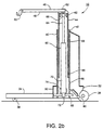
- the assist mechanism 10 has a generally U-shaped base weldment 30 as viewed in Fig. 2a, consisting of a rectangular member 32 with two widely spaced perpendicular legs 34 extending therefrom.
- the base weldment 30 is supported for movement on two rear wheels 36 mounted at the outer ends of the rectangular member 32 and two small front swivel wheels 38 on the leg ends to provide stability to the assist mechanism 10 while supporting and moving the supply cassette.
- a vertically upright support 40 has a hollow outer tube 42 fixed to the rectangular member 32 and an inner tube 44 telescopically mounted within the outer tube 42.
- a generally U-shaped bracket 46 is fixed to the top of the inner tube 44 at a middle portion of the U-shaped bracket 46.
- the bracket 46 has two arms 48 extending in same direction as the legs 34 of the base weldment 30.
- the arms 48 are provided with end hooks 50 to carry a supply roll or a supply cassette containing a supply roll (Fig. 1).
- Two handle grips 52 are provided on opposite sides of the upright support 40 for a user to grip the bracket 46 with during movement of the assist mechanism 10.
- the upright support 40 is equipped with an actuator 60 to vertically raise and lower the inner tube 44 telescopically with respect to the outer tube 42.
- a horizontal top pin 62 is attached inside the top of the inner tube 44 and is coupled to a translating tube 64 of the actuator 60 through a first clevis end 66.
- a horizontal bottom pin 68 is attached inside the bottom of the outer tube 42 and is coupled to a fixed tube 70 of the actuator 60 through a second clevis end 72.
- the translating tube 64 is telescopic with respect to the fixed tube 70.
- the actuator 60 is driven by an attached D.C. motor 74 which rotates a screw inside the fixed tube 70 through conventional gearing, causing linear movement of a traveling nut secured to the inside of the translating tube 64 (not shown).
- the operation of the actuator 60 is not unique to the present invention and is considered to be known in the art.
- Such actuators are available from DUFF-NORTON® as for example MINI-PACTM Actuators, 6405 series.
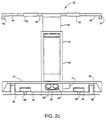
- the D.C. motor 74 of the actuator 60 is controlled by a foot switch 80 which has two pedals 82, 84, shown in Fig. 2c.
- a first pedal drives the motor in a first direction corresponding to raising the translating tube 64 of the actuator 60 and the attached inner tube 44 of the upright support 40, causing the bracket 46 to be raised with the movement of the telescopic inner tube 44.
- a second pedal drives the motor 74 in an opposite direction corresponding to lowering the translating tube 64 and the attached inner tube 44 of the upright support 40, causing the bracket 46 to be lowered with the movement of the inner tube 44.
- Limit switches 86, 88 are located on the inner and outer tubes 44, 42 respectively, to signal the actuator motor 74 to shut off when the telescopic inner tube 44 reaches its upper and lower vertical limits.
- the assist mechanism is generally used to install or remove a supply cassette from the supply cassette docking area in the imagesetter.
- a supply cassette requires reloading with a new supply roll
- the operator can manually remove the relatively light empty supply cassette and then reload it with a new supply roll at a remote work surface.
- a supply roll 53 is mounted on a supply roll bearing 51 which passes through the core 56 of the supply roll 53 and protrudes from the ends of the supply cassette when the supply roll 53 is contained within the supply cassette.
- the roll bearing ends 51 allow the supply roll 53 to be handled without the user's hands touching the media. It is advantageous to reduce direct handling of the media by the user as some media is sensitive to finger and hand prints.
- the bearing ends 51 also support the supply roll 53 for unwinding of the media from the supply roll during use, and cooperate with grooved mounting brackets 57 (Fig. 1) to guide the supply cassette into the docked position.
- the operator uses the assist mechanism to lift the heavy reloaded supply cassette from the work surface and place it in the imagesetter.
- the assist mechanism 10 is rolled to the work surface 90 by an operator 100 and the bracket 46 is aligned with the supply cassette 14.
- the operator 100 then uses the foot switch to raise or lower the bracket 46 to position the arms 48 at a height between the work surface 90 and the ends of the roll bearing 51 extending through the supply cassette 14, located at about mid-height on the supply cassette 14.
- the assist mechanism 10 is then manually maneuvered by the operator 100 so that the end hooks 50 on the arms 48 of the bracket 46 are positioned underneath the bearing ends 51 of the supply cassette 14.
- the operator 100 then uses the foot switch to raise the bracket 46 so that the ends of the roll bearing 51 are engaged by the end hooks 50 to cradle the supply cassette 14 in the arms 48 of the assist mechanism 10 and lift the supply cassette 14 from the work surface 90.
- the assist mechanism 10 is then rolled by the operator 100 to be adjacent to the imagesetter's supply cassette docking area 16.
- the operator uses the foot switch to vertically raise or lower the bracket 46 to a height above the desired support tray 18 for the supply cassette 14, which is pulled out from the docked position to an access position. Then the foot switch is used by the operator 100 to lower the supply cassette 14 into the selected support tray 18. Once the supply cassette 14 is resting in the support tray 18, the bracket is lowered slightly to unhook the bracket end hooks 50 from the roll bearing 51. Then the assist mechanism is rolled away by the operator as in Fig. 5, clearing the arms 48 of the bracket 46 from the docking area 16.
- a latching mechanism on the support tray cooperates with a pin on each end of the supply cassette (not shown), to secure the supply cassette in a fixed relationship with respect to the support tray.
- the operator manually locks the supply cassette into the support tray and positions the support tray into the docked location.
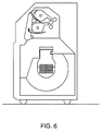
- Figure 6 shows the support trays 18, 20 both in the docked position. Once the supply cassette is in the docked location the imagesetter automatically positions the media for use so the imagesetter can draw upon the media supply when needed.
- the assist mechanism is also useful for removing a supply cassette from a support tray in the imagesetter when the operator wishes to change types of media, in which case the installed supply roll need not be empty.
- the supply roll being removed can be a relatively new roll and therefore will be heavy and difficult for a single operator to handle, particularly if large format media is being handled.
- the supply roll is removed in the following manner. Referring to Fig. 7, the supply cassette requiring a supply roll replacement is moved by the operator from the docked position to the access position.
- the supply cassette 22 has a hinged flip cover which accommodates the bearing ends 51 extending past the ends of the supply cassette 22.
- the cassette cover is flipped opened, exposing the supply roll to be removed from the cassette.
- the assist mechanism 10 is then rolled by the operator 100 to the supply roll 53 such that the end hooks 50 are positioned at the ends of the roll bearing 51 extending through the supply cassette casing 22.
- the operator 100 then uses the foot switch to vertically raise the supply roll 53 by the bearing ends 51, out of the supply cassette 22, while the supply cassette 22 remains in the support tray 20 due to the latching mechanism (not shown).
- the foot switch is released to stop the assist mechanism, and then the assist mechanism 10 is rolled to a remote location such as a work surface 90 shown in Fig. 3.
- the supply roll 53 is then lowered down to the work surface 90 by use of the foot switch, and the roll bearing ends 51 are released from the end hooks 50 as the arms 48 of the bracket 46 are lowered.
- the roll bearing 51 is then removed from the core of the supply roll 53 and is inserted into the core of the replacement supply roll, or alternatively each supply roll may be equipped with an individual roll bearing.
- the replacement supply roll may then be lifted by the roll bearing ends 51 with the assist mechanism 10 in a manner similar to that previously described for installing the supply cassette 14 into the support tray 20, however the supply cassette is mounted in the support tray rather than enclosing the supply roll.
- the supply roll 52 is moved from the work surface 90 with the assist mechanism 10, with no manual lifting required by the operator 100, and placed into the open supply cassette 14 in the support tray 20 of the imagesetter 12.
- the cover of the supply cassette 14 is then closed and the tray 20 is moved from the access position shown in Fig. 7 to the docked position shown in Fig. 6.
Landscapes
- Replacement Of Web Rolls (AREA)
- Projection-Type Copiers In General (AREA)
Claims (8)
- Mécanisme d'aide (10) destiné à être utilisé par un opérateur (100) pour installer une alimentation en support (14, 53) dans une flasheuse (12), comprenant :a. un bâti en forme de U (30) supporté par des moyens de positionnement (36, 38) permettant à l'opérateur (100) d'aider à positionner et à déplacer aisément ledit bâti (30) par rapport à la flasheuse (12), le bâti comprenant un organe (32) duquel se prolongent deux pieds espacés (34), chaque pied comprenant une partie (38) desdits moyens de positionnement ;b. un montant vertical (40) fixé à la partie milieu de l'organe (32) du bât ;c. un moyen porteur (46) comprenant une console généralement en forme de U (46) fixée en sa partie milieu au sommet du montant (40) sur laquelle sont montés deux bras espacés (48) s'en prolongeant dans la même direction que les pieds (34) et pourvus, à leur extrémité, de moyens pour maintenir (50) ladite alimentation en support (14),
le montant (40) étant équipé de moyens de réglage vertical comprenant un actionneur (60) pour déplacer automatiquement verticalement le moyen porteur (46) de manière linéaire verticale par rapport au bâti (30); etd. un moyen de commande (80) pour commander lesdits moyens de réglage vertical (60),
le mécanisme d'aide permettant à l'opérateur d'installer et de retirer aisément une cassette d'alimentation en support (14) dans et de la flasheuse (12), ou de recharger aisément une cassette d'alimentation en support en remplaçant le rouleau d'alimentation (53) sans retirer la cassette (14) de la flasheuse (12). - Mécanisme d'aide selon la revendication 1,
dans lequel ledit actionneur est relié à des tubes creux (42, 44) télescopiquement mobiles l'un par rapport à l'autre. - Mécanisme d'aide selon la revendication 1 ou 2,
dans lequel l'alimentation en support (53) est contenue dans une cassette d'alimentation en support (14). - Mécanisme d'aide selon l'une des revendications précédentes,
dans lequel l'alimentation en support (53) est un support de type bande sous forme d'un rouleau d'alimentation. - Appareil d'installation d'alimentation en support, comprenantune flasheuse (12) comportant un emplacement d'ancrage (18) pour maintenir une alimentation en support de type bande (14) sous forme d'un rouleau d'un support d'enregistrement d'image (53), une surface porteuse de support (24) pour porter le support retiré du rouleau dans l'emplacement d'ancrage, et un appareil de reproduction d'image par balayage (26) pour reproduire une image par balayage sur le support placé sur la surface porteuse de support (24) ; etun mécanisme d'aide (10) selon l'une des revendications 1 à 4 pour aider un opérateur (100) à installer et à retirer l'alimentation en support (14) dans et de l'emplacement d'ancrage (18) dans ladite flasheuse (12).
- Appareil selon la revendication 5,
dans lequel ledit mécanisme d'aide (10) règle automatiquement la position de l'alimentation en support (14) par rapport à l'emplacement d'ancrage (18) lorsque l'opérateur (100) utilise ledit moyen de commande (80). - Appareil selon la revendication 6,
dans lequel lesdits moyens de réglage vertical (60) règlent la position verticale de l'alimentation en support (14) par rapport à l'emplacement d'ancrage (18) dans la flasheuse (12) et lesdits moyens de positionnement (36, 38) règlent la position horizontale de l'alimentation en support (14) par rapport à l'emplacement d'ancrage (18) dans la flasheuse (12). - Appareil selon l'une des revendications 5 à 7,
dans lequel l'alimentation en support (53) est contenue dans une cassette d'alimentation en support (14) et ledit mécanisme d'aide (10) aide un opérateur (100) à installer et à retirer la cassette d'alimentation en support (14) contenant l'alimentation en support (53) dans et de l'emplacement d'ancrage (18).
Applications Claiming Priority (2)
| Application Number | Priority Date | Filing Date | Title |
|---|---|---|---|
| US309812 | 1994-09-21 | ||
| US08/309,812 US5542623A (en) | 1994-09-21 | 1994-09-21 | Method and apparatus for installing a media supply cassette in an imagesetter |
Publications (2)
| Publication Number | Publication Date |
|---|---|
| EP0708048A1 EP0708048A1 (fr) | 1996-04-24 |
| EP0708048B1 true EP0708048B1 (fr) | 2002-06-26 |
Family
ID=23199764
Family Applications (1)
| Application Number | Title | Priority Date | Filing Date |
|---|---|---|---|
| EP95113871A Expired - Lifetime EP0708048B1 (fr) | 1994-09-21 | 1995-09-04 | Méthode et appareil pour installer une cassette d'alimentation de supports dans un compositeur d'image |
Country Status (4)
| Country | Link |
|---|---|
| US (1) | US5542623A (fr) |
| EP (1) | EP0708048B1 (fr) |
| JP (1) | JPH0895162A (fr) |
| DE (1) | DE69527179T2 (fr) |
Families Citing this family (6)
| Publication number | Priority date | Publication date | Assignee | Title |
|---|---|---|---|---|
| US5964024A (en) * | 1997-06-25 | 1999-10-12 | Norkol/Fibercore, Inc. | Roll cutter |
| US5947407A (en) * | 1998-08-03 | 1999-09-07 | Quigley; John C. | In-line automated roll stand |
| IT1316141B1 (it) * | 2000-09-15 | 2003-03-28 | Durst Phototechnik Ag | Dispositivo di caricamento e scaricamento per materiali in rullinonche' combinazione di un dispositivo di stampa con un dispositivo di |
| US20050210839A1 (en) * | 2004-03-24 | 2005-09-29 | Sealed Air Corporation (Us) | Overhead packaging cushion supply system |
| CN107416565B (zh) * | 2016-05-23 | 2019-08-13 | 东莞市雅康精密机械有限公司 | 分切设备及其双卷轴卸料装置 |
| TWI758127B (zh) * | 2021-03-11 | 2022-03-11 | 全利機械股份有限公司 | 紙捲換捲機構 |
Family Cites Families (17)
| Publication number | Priority date | Publication date | Assignee | Title |
|---|---|---|---|---|
| US2622816A (en) * | 1949-05-06 | 1952-12-23 | Associated Patentees Inc | Coil cradle |
| FR1206332A (fr) * | 1958-07-21 | 1960-02-09 | Alltex France | élévateur d'ensouple sur chariot |
| BE757948A (fr) * | 1970-08-28 | 1971-04-23 | Kalle Ag | Dispositif d'emmagasinage pour des rouleaux d'alimentation dansdes appareils de reproduction |
| US4273501A (en) * | 1978-10-23 | 1981-06-16 | Terry Melvin D | Roll handling device |
| US4266903A (en) * | 1979-08-27 | 1981-05-12 | Offset Newspaper Equipment Inc. | Lifting dollie |
| US4299458A (en) * | 1980-06-02 | 1981-11-10 | Autologic, Inc. | Self threading phototypesetter transport system |
| GB2114099A (en) * | 1982-01-28 | 1983-08-17 | Linotype Paul Ltd | Positioning intermittently fed film on concave back plate for exposure |
| DE3318311A1 (de) * | 1983-05-19 | 1984-11-22 | Dr. Böger Photosatz GmbH, 2000 Wedel | Optische lichtfleck-abtastvorrichtung fuer ein photoempfindliches bahnmaterial bei optischen photosetzgeraeten |
| CH664309A5 (en) * | 1984-06-13 | 1988-02-29 | Hans Sieber | Coiled material storage equipment - has travelling stacking machine with material feed mechanism and shear |
| US4593883A (en) * | 1984-12-10 | 1986-06-10 | Nelson Richard P | Portable lifting, loading and transporting device |
| DE3517696A1 (de) * | 1985-05-17 | 1986-11-20 | Paul Troester Maschinenfabrik, 3000 Hannover | Vorrichtung zum aufwickeln von kaben auf kabeltrommeln |
| BE1003809A3 (nl) * | 1990-02-27 | 1992-06-16 | Picanol Nv | Inrichting voor het bevestigen van een element in een zitting. |
| US5134915A (en) * | 1990-03-19 | 1992-08-04 | Mita Industrial Co., Ltd. | Rolled-paper feed unit for an image forming apparatus |
| JPH0437525A (ja) * | 1990-06-01 | 1992-02-07 | Somar Corp | ラミネータ用ロール搬送着脱装置 |
| DE4037671A1 (de) * | 1990-11-27 | 1992-06-04 | Sundwiger Eisen Maschinen | Positioniervorrichtung fuer auf eine haspeltrommel aufzusteckende bunde, insbesondere aus metallband |
| US5246180A (en) * | 1991-12-23 | 1993-09-21 | Southwire Company | Reel support with horizontal and vertical adjustment |
| US5421691A (en) * | 1993-03-23 | 1995-06-06 | Ferrone; Rock A. | Roll transfer device |
-
1994
- 1994-09-21 US US08/309,812 patent/US5542623A/en not_active Expired - Fee Related
-
1995
- 1995-09-04 DE DE69527179T patent/DE69527179T2/de not_active Expired - Fee Related
- 1995-09-04 EP EP95113871A patent/EP0708048B1/fr not_active Expired - Lifetime
- 1995-09-13 JP JP7259535A patent/JPH0895162A/ja active Pending
Also Published As
| Publication number | Publication date |
|---|---|
| DE69527179D1 (de) | 2002-08-01 |
| DE69527179T2 (de) | 2003-01-23 |
| EP0708048A1 (fr) | 1996-04-24 |
| JPH0895162A (ja) | 1996-04-12 |
| US5542623A (en) | 1996-08-06 |
Similar Documents
| Publication | Publication Date | Title |
|---|---|---|
| US6904844B2 (en) | Printing plate removing/supplying device | |
| JPH04209138A (ja) | 給紙カセット並びにこの給紙カセットを用いた画像形成装置 | |
| US5542623A (en) | Method and apparatus for installing a media supply cassette in an imagesetter | |
| EP0692739B1 (fr) | Procédé et dispositif pour pont de transport de moyens monté de façon pivotante avec un système de contrepoids amelioré | |
| EP0846638A2 (fr) | Dispositif et procédé pour charger et décharger un médium en forme de feuille | |
| US4655583A (en) | Apparatus for transporting a web of photosensitive material in a photo printer | |
| US4707125A (en) | Photographic registration apparatus and method | |
| EP1473153B1 (fr) | Procédé et dispositif de chargement et de déchargement de plaques d'impression flexographiques dans un système d'enregistrement "ordinateur à plaque" | |
| US5684570A (en) | Method and apparatus for manipulation of large format media supply cassettes | |
| US5187520A (en) | Photographic copying apparatus | |
| US6229591B1 (en) | Photographic processor | |
| JPH1138582A (ja) | ペーパマガジンの案内装置 | |
| US4529300A (en) | Magazine device with suction boxes | |
| JP3058633B1 (ja) | 合紙取出し装置 | |
| US5207413A (en) | Vacuum sheet film transport and method | |
| JP3770927B2 (ja) | 原反ロールホルダーへの装着用原反ロールリフター | |
| JPH01956A (ja) | 写真フィルム搬送装置 | |
| JPH02132023A (ja) | 画像形成装置 | |
| JP2783506B2 (ja) | マガジン着脱装置 | |
| JPH01179029A (ja) | 写真感光材料のマガジン収納装置 | |
| JPH06135577A (ja) | 画像形成装置の給紙装置 | |
| JPH04257840A (ja) | 写真用プリント装置 | |
| US6598875B2 (en) | Original-affixing device | |
| JPH11109700A (ja) | 画像形成装置 | |
| JP2007334266A (ja) | 感光性印刷版の自動供給装置 |
Legal Events
| Date | Code | Title | Description |
|---|---|---|---|
| PUAI | Public reference made under article 153(3) epc to a published international application that has entered the european phase |
Free format text: ORIGINAL CODE: 0009012 |
|
| AK | Designated contracting states |
Kind code of ref document: A1 Designated state(s): BE DE FR GB |
|
| RAP1 | Party data changed (applicant data changed or rights of an application transferred) |
Owner name: BAYER CORPORATION |
|
| 17P | Request for examination filed |
Effective date: 19961016 |
|
| 17Q | First examination report despatched |
Effective date: 19990428 |
|
| RAP1 | Party data changed (applicant data changed or rights of an application transferred) |
Owner name: AGFA CORPORATION |
|
| GRAG | Despatch of communication of intention to grant |
Free format text: ORIGINAL CODE: EPIDOS AGRA |
|
| GRAG | Despatch of communication of intention to grant |
Free format text: ORIGINAL CODE: EPIDOS AGRA |
|
| GRAH | Despatch of communication of intention to grant a patent |
Free format text: ORIGINAL CODE: EPIDOS IGRA |
|
| GRAH | Despatch of communication of intention to grant a patent |
Free format text: ORIGINAL CODE: EPIDOS IGRA |
|
| GRAA | (expected) grant |
Free format text: ORIGINAL CODE: 0009210 |
|
| AK | Designated contracting states |
Kind code of ref document: B1 Designated state(s): BE DE FR GB |
|
| REG | Reference to a national code |
Ref country code: GB Ref legal event code: FG4D |
|
| REF | Corresponds to: |
Ref document number: 69527179 Country of ref document: DE Date of ref document: 20020801 |
|
| ET | Fr: translation filed | ||
| PLBE | No opposition filed within time limit |
Free format text: ORIGINAL CODE: 0009261 |
|
| STAA | Information on the status of an ep patent application or granted ep patent |
Free format text: STATUS: NO OPPOSITION FILED WITHIN TIME LIMIT |
|
| 26N | No opposition filed |
Effective date: 20030327 |
|
| PGFP | Annual fee paid to national office [announced via postgrant information from national office to epo] |
Ref country code: FR Payment date: 20030827 Year of fee payment: 9 |
|
| PGFP | Annual fee paid to national office [announced via postgrant information from national office to epo] |
Ref country code: GB Payment date: 20030828 Year of fee payment: 9 Ref country code: BE Payment date: 20030828 Year of fee payment: 9 |
|
| PGFP | Annual fee paid to national office [announced via postgrant information from national office to epo] |
Ref country code: DE Payment date: 20030902 Year of fee payment: 9 |
|
| PG25 | Lapsed in a contracting state [announced via postgrant information from national office to epo] |
Ref country code: GB Free format text: LAPSE BECAUSE OF NON-PAYMENT OF DUE FEES Effective date: 20040904 |
|
| PG25 | Lapsed in a contracting state [announced via postgrant information from national office to epo] |
Ref country code: BE Free format text: LAPSE BECAUSE OF NON-PAYMENT OF DUE FEES Effective date: 20040930 |
|
| BERE | Be: lapsed |
Owner name: *AGFA CORP. Effective date: 20040930 |
|
| PG25 | Lapsed in a contracting state [announced via postgrant information from national office to epo] |
Ref country code: DE Free format text: LAPSE BECAUSE OF NON-PAYMENT OF DUE FEES Effective date: 20050401 |
|
| GBPC | Gb: european patent ceased through non-payment of renewal fee |
Effective date: 20040904 |
|
| PG25 | Lapsed in a contracting state [announced via postgrant information from national office to epo] |
Ref country code: FR Free format text: LAPSE BECAUSE OF NON-PAYMENT OF DUE FEES Effective date: 20050531 |
|
| REG | Reference to a national code |
Ref country code: FR Ref legal event code: ST |
|
| BERE | Be: lapsed |
Owner name: *AGFA CORP. Effective date: 20040930 |