EP0846638A2 - Dispositif et procédé pour charger et décharger un médium en forme de feuille - Google Patents
Dispositif et procédé pour charger et décharger un médium en forme de feuille Download PDFInfo
- Publication number
- EP0846638A2 EP0846638A2 EP97870154A EP97870154A EP0846638A2 EP 0846638 A2 EP0846638 A2 EP 0846638A2 EP 97870154 A EP97870154 A EP 97870154A EP 97870154 A EP97870154 A EP 97870154A EP 0846638 A2 EP0846638 A2 EP 0846638A2
- Authority
- EP
- European Patent Office
- Prior art keywords
- drum
- sheet
- medium
- film
- take
- Prior art date
- Legal status (The legal status is an assumption and is not a legal conclusion. Google has not performed a legal analysis and makes no representation as to the accuracy of the status listed.)
- Withdrawn
Links
Images



Classifications
-
- H—ELECTRICITY
- H04—ELECTRIC COMMUNICATION TECHNIQUE
- H04N—PICTORIAL COMMUNICATION, e.g. TELEVISION
- H04N1/00—Scanning, transmission or reproduction of documents or the like, e.g. facsimile transmission; Details thereof
- H04N1/00567—Handling of original or reproduction media, e.g. cutting, separating, stacking
- H04N1/0057—Conveying sheets before or after scanning
- H04N1/00588—Conveying sheets before or after scanning to the scanning position
-
- B—PERFORMING OPERATIONS; TRANSPORTING
- B65—CONVEYING; PACKING; STORING; HANDLING THIN OR FILAMENTARY MATERIAL
- B65H—HANDLING THIN OR FILAMENTARY MATERIAL, e.g. SHEETS, WEBS, CABLES
- B65H29/00—Delivering or advancing articles from machines; Advancing articles to or into piles
- B65H29/54—Article strippers, e.g. for stripping from advancing elements
- B65H29/56—Article strippers, e.g. for stripping from advancing elements for stripping from elements or machines
-
- B—PERFORMING OPERATIONS; TRANSPORTING
- B65—CONVEYING; PACKING; STORING; HANDLING THIN OR FILAMENTARY MATERIAL
- B65H—HANDLING THIN OR FILAMENTARY MATERIAL, e.g. SHEETS, WEBS, CABLES
- B65H3/00—Separating articles from piles
- B65H3/08—Separating articles from piles using pneumatic force
- B65H3/0808—Suction grippers
- B65H3/0816—Suction grippers separating from the top of pile
- B65H3/0833—Suction grippers separating from the top of pile and acting on the front part of the articles relatively to the final separating direction
-
- H—ELECTRICITY
- H04—ELECTRIC COMMUNICATION TECHNIQUE
- H04N—PICTORIAL COMMUNICATION, e.g. TELEVISION
- H04N1/00—Scanning, transmission or reproduction of documents or the like, e.g. facsimile transmission; Details thereof
- H04N1/00567—Handling of original or reproduction media, e.g. cutting, separating, stacking
- H04N1/0057—Conveying sheets before or after scanning
- H04N1/00591—Conveying sheets before or after scanning from the scanning position
-
- H—ELECTRICITY
- H04—ELECTRIC COMMUNICATION TECHNIQUE
- H04N—PICTORIAL COMMUNICATION, e.g. TELEVISION
- H04N1/00—Scanning, transmission or reproduction of documents or the like, e.g. facsimile transmission; Details thereof
- H04N1/00567—Handling of original or reproduction media, e.g. cutting, separating, stacking
- H04N1/0057—Conveying sheets before or after scanning
- H04N1/00599—Using specific components
- H04N1/00602—Feed rollers
-
- H—ELECTRICITY
- H04—ELECTRIC COMMUNICATION TECHNIQUE
- H04N—PICTORIAL COMMUNICATION, e.g. TELEVISION
- H04N1/00—Scanning, transmission or reproduction of documents or the like, e.g. facsimile transmission; Details thereof
- H04N1/00567—Handling of original or reproduction media, e.g. cutting, separating, stacking
- H04N1/0057—Conveying sheets before or after scanning
- H04N1/00599—Using specific components
- H04N1/00607—Grippers or the like, e.g. suction grippers
-
- H—ELECTRICITY
- H04—ELECTRIC COMMUNICATION TECHNIQUE
- H04N—PICTORIAL COMMUNICATION, e.g. TELEVISION
- H04N1/00—Scanning, transmission or reproduction of documents or the like, e.g. facsimile transmission; Details thereof
- H04N1/00567—Handling of original or reproduction media, e.g. cutting, separating, stacking
- H04N1/0057—Conveying sheets before or after scanning
- H04N1/00599—Using specific components
- H04N1/0061—Feed belts
-
- H—ELECTRICITY
- H04—ELECTRIC COMMUNICATION TECHNIQUE
- H04N—PICTORIAL COMMUNICATION, e.g. TELEVISION
- H04N1/00—Scanning, transmission or reproduction of documents or the like, e.g. facsimile transmission; Details thereof
- H04N1/00567—Handling of original or reproduction media, e.g. cutting, separating, stacking
- H04N1/0062—Removing sheets from a stack or inputting media
-
- H—ELECTRICITY
- H04—ELECTRIC COMMUNICATION TECHNIQUE
- H04N—PICTORIAL COMMUNICATION, e.g. TELEVISION
- H04N1/00—Scanning, transmission or reproduction of documents or the like, e.g. facsimile transmission; Details thereof
- H04N1/00567—Handling of original or reproduction media, e.g. cutting, separating, stacking
- H04N1/00628—Separating, e.g. preventing feeding of two sheets at a time
-
- H—ELECTRICITY
- H04—ELECTRIC COMMUNICATION TECHNIQUE
- H04N—PICTORIAL COMMUNICATION, e.g. TELEVISION
- H04N1/00—Scanning, transmission or reproduction of documents or the like, e.g. facsimile transmission; Details thereof
- H04N1/04—Scanning arrangements, i.e. arrangements for the displacement of active reading or reproducing elements relative to the original or reproducing medium, or vice versa
- H04N1/06—Scanning arrangements, i.e. arrangements for the displacement of active reading or reproducing elements relative to the original or reproducing medium, or vice versa using cylindrical picture-bearing surfaces, i.e. scanning a main-scanning line substantially perpendicular to the axis and lying in a curved cylindrical surface
- H04N1/08—Mechanisms for mounting or holding the sheet around the drum
- H04N1/083—Holding means
- H04N1/0856—Suction or vacuum means
-
- H—ELECTRICITY
- H04—ELECTRIC COMMUNICATION TECHNIQUE
- H04N—PICTORIAL COMMUNICATION, e.g. TELEVISION
- H04N1/00—Scanning, transmission or reproduction of documents or the like, e.g. facsimile transmission; Details thereof
- H04N1/04—Scanning arrangements, i.e. arrangements for the displacement of active reading or reproducing elements relative to the original or reproducing medium, or vice versa
- H04N1/06—Scanning arrangements, i.e. arrangements for the displacement of active reading or reproducing elements relative to the original or reproducing medium, or vice versa using cylindrical picture-bearing surfaces, i.e. scanning a main-scanning line substantially perpendicular to the axis and lying in a curved cylindrical surface
- H04N1/08—Mechanisms for mounting or holding the sheet around the drum
- H04N1/0895—Means other than holding means for removing the sheet form the drum
Definitions
- the present invention relates to a device and a method for loading a sheet-like medium without tension onto a drum, and to a device and a method for unloading a sheet-like medium from a drum.
- the drum may be a vacuum drum of an imagesetter for example, or a vacuum drum of an input scanning machine or a scanning device.
- European patent application EP-A2-0 228 545 discloses a film applying and removing device in a drum type image recording scanning apparatus in which the tip end of a film is ascended so as to contact the surface of the drum. Vacuum suction means directly takes the film. This device has a disadvantage: if the film is not perfectly aligned with the drum, it will wrap around the drum at a slant.
- Exposed media are often removed from a drum by using suction caps as well. This takes quite a lot of time, as the suction caps need to be moved from the exposed medium wrapped around the drum to an acceptance device such as an unload tray or a developing machine.
- European patent EP-0 533 145 discloses an apparatus and a method for removing a sheet from a hollow drum member.
- the apparatus includes means for supplying a vacuum to the interior of the drum, and two sets of vacuum openings through the surface of the drum member.
- the sheet is arranged to overlay and close the first set of vacuum openings with the second set of openings extending substantially parallel with an edge of the sheet and comprising only a small portion of the total number of vacuum openings through the drum.
- An exit blade is disposed adjacent to the drum and has an edge proximate to the drum that extends substantially parallel to the edge of the sheet.
- the exit blade is disposed with respect to the drum so as to form an acute angle with the surface thereof with the proximate edge of the blade closely adjacent the apex of the angle and parallel with the edge of the sheet so that, when the drum is rotated to a sheet removal position, the first set of vacuum openings lies beneath the acute angle when the edge of the sheet is disposed on the opposite side of the apex.
- the method comprises the steps of: rotating the drum to a sheet removal position where the first set of vacuum openings lie beneath the acute angle and the edge of the sheet is disposed on the opposite side of the apex, and drawing air through the second set of vacuum openings by the vacuum in the drum and creating an area of sufficiently high pressure air at the apex to cause air to be forced past the edge of the exit blade with sufficient force to lift the edge of the sheet from the surface of the drum.
- This apparatus and method have the disadvantage that means need to be provided for blowing air through the second set of openings in order to remove the sheet from the drum.
- One aim of the invention is to wrap a sheet-like medium, such as a photosensitive film or a flexible plate, around a drum of a scanning device such as an input scanner or an imagesetter, in a tensionless manner.
- a sheet-like medium such as a photosensitive film or a flexible plate
- a scanning device such as an input scanner or an imagesetter
- a loading device for loading a sheet-like medium on a drum.
- This loading device comprises means for supplying a vacuum to the interior of said drum, a material supply device which is able to contain at least one sheet-like medium, and a mechanical device which is able to take a sheet-like medium from the material supply device and move it to the drum.
- the loading device also comprises take-over means which are able to present the sheet-like medium to the drum without any tension.
- these take-over means consist of a lower device and an upper device, whereby the lower device may be for example a take-over plate and the upper device may be a take-over cylinder.
- the upper device and the lower device are movable relative to each other. There exists a position of the upper and the lower device where the upper device has one point that touches a point of the lower device.
- the invention also provides a method for loading a sheet-like medium onto a drum of an apparatus.
- the apparatus comprises a material supply device, means for supplying a vacuum to the interior of the drum, a mechanical device and take-over means.
- the method comprises the steps of: taking a sheet-like medium from the material supply device with the help of the mechanical device which is positioned in an initial position, moving the sheet-like medium towards the drum by moving the mechanical device from its initial position to an end position whereby the leading edge of the sheet-like medium is arranged to be taken by the vacuum of the drum, holding the sheet-like medium without tension by means of the take-over means, rotating the drum to a load position, turning a vacuum on in the drum, releasing the sheet-like medium by releasing the take-over means, wrapping the sheet-like medium around the drum and returning the mechanical device to its initial position.
- a second aim of the invention is to unload a sheet-like medium from a drum of an apparatus.
- an unloading device is foreseen which comprises a transport mechanism, a movable unload table and an upper roll.
- the upper roll is suitable for being positioned on the drum, while the unload table is appropriate for being moved from an initial position away from the drum to an end position, whereby one edge of the unload table, extending substantially parallel to the width of the drum, is disposed closely adjacent to the drum.
- the unloading device may comprise an unload bottom plate, specially prepared so as not to make scratches on the medium.
- the invention also provides a method for unloading a sheet-like medium from the drum of an apparatus, the sheet-like medium being wrapped around the drum and held around it by means of a high vacuum provided to the interior of the drum.
- the apparatus comprises an unload table and an upper roll. The initial positions of both means are away from the drum. The end positions of both means are adjacent to the drum.
- the method comprises the steps of: rotating the drum to an unload position, putting the table and the upper roll down, releasing the high vacuum in the drum, rotating the drum to remove the sheet-like medium, and returning the table and the upper roll to their initial positions.
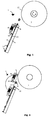
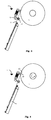
- FIG. 1 through 6 are schematic views showing the main parts of a loading device according to the present invention. They present the different stages during the load process of a sheet-like medium.
- Fig. 1 shows all parts in their initial positions.
- Fig. 2 shows a mechanical device taking a sheet-like medium and moving it to the drum.
- Fig. 3 shows a sheet-like medium being held by the take-over means.
- Fig. 4 shows the alignment of the sheet-like medium towards the drum.
- Fig. 5 shows the drum taking over the sheet-like medium and the take-over means releasing it.
- Fig. 6 shows the sheet-like material being wrapped around the drum, and the mechanical device returning to its initial position.
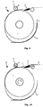
- Fig. 7 through 11 are schematic views showing the main parts of the unload device of an imagesetter. They present the different stages during the unload process of the sheet-like medium.
- Fig. 7 shows the table and the upper roll in their initial positions, the drum being rotated towards an unload point.
- Fig. 8 shows the table and the upper roll put down.
- Fig. 9 shows the situation when the vacuum is released.
- Fig. 10 shows the sheet-like medium being put on the transport mechanism.
- Fig. 11 shows the upper roll and the table returning to their initial positions.
- FIG. 1 through 6 A loading device for a sheet-like medium according to the present invention is illustrated in Fig. 1 through 6.
- the overall apparatus is a scanning device such as an input scanner or an imagesetter.
- the sheet-like medium is a film.
- Other applications are also within the scope of the present invention.
- microprocessor All mechanical movements of the apparatus are governed by a microprocessor (not shown), the software of which (called hereinafter machine software) commands and controls the movements and handles error messages. How to incorporate such microprocessor control is well known in the art.
- Fig. 1 shows a loading device 1 for loading a film 2 on a drum 3.
- a loading device 1 comprises means (not shown) for supplying a vacuum to the interior of drum 3.
- These means may be a vacuum pump which is connected to drum 3 in a non-frictional way via a flexible tube. The vacuum is needed because during operation of the apparatus, drum 3 spins at high speed, and should prevent film 2 from falling off drum 3.
- Loading device 1 also comprises a material supply device 4 in which one film 2 or a stack of films 2 can be placed.
- material supply device 4 in the preferred embodiment is a load cassette, the depth of the bottom 5 of the cassette changing according to the amount of films 2 that are put in.
- a spring 6 on the bottom 5 pushes films 2 outwardly towards a fixed point. Due to spring 6, the position of the first film 2, being the only film 2 in the cassette 4 or the film 2 on top of the stack, is always equal, no matter how many films 2 are in load cassette 4.
- Load cassette 4 can be adapted for use of different sizes of films 2, by means of size adapters 7. No cover is mounted on load cassette 4. This provides very easy access for loading films 2 into load cassette 4.
- the initial position of a mechanical device 8, provided with several suction caps 9 and a take-over cylinder 10 (the upper device of the take-over means), is such that suction caps 9 slightly touch first film 2.
- a film 2 has to be loaded on drum 3 of the scanning device such as an imagesetter or input scanner, a low vacuum is applied to suction caps 9, and the first film 2 to be exposed is pulled towards mechanical device 8.
- no vacuum can be formed. This can be detected in a manner known in the art, and causes the microprocessor to generate and handle an error message.
- drum 3 While taking film 2 to be exposed, drum 3 rotates at a slow speed towards a first load position.
- Drum 3 is provided with a mechanical stop 12, and the first load position is a position of drum 3 such that, when a film 2 is presented to drum 3, it will not hit mechanical stop 12.
- the first load position can be changed via a parameter in the software for operating the apparatus.
- the rotation of drum 3 for reaching the first load position can be clockwise or counter-clockwise, depending on the initial position of drum 3.
- the software for operating the apparatus detects in which direction the drum should be turned in order to cover the shortest distance.
- a take-over cylinder 10 is positioned on mechanical device 8 so it will move with mechanical device 8.
- Take-over cylinder 10 is positioned in the middle of the width of drum 3 and films 2 will always be centered on the width of drum 3 due to size adapters 7. This means that the take-over cylinder is positioned in the middle of the width of film 2.
- take-over cylinder 10 When mechanical device 8 has finished its movement, take-over cylinder 10 is positioned in front of a take-over plate 11 (the lower device of the take-over means) lying substantially parallel to the surface of drum 3. Take-over cylinder 10 is put down until it slightly hits take-over plate 11 (Fig. 3).
- Drum 3 will rotate counter-clockwise towards a second load point.
- a mechanical stop 12 on drum 3, formed by an upstanding surface 13 and a flattened surface 14, is provided.
- the second load point is the point whereby film 2, the leading edge of which rests on flattened surface 14, just hits upstanding surface 13.
- the position of drum 3 is again controlled via a parameter in the machine software.
- the speed of drum 3 for arriving at the right position is very low.
- This procedure is the alignment of film 2 towards drum 3. Thanks to mechanical stop 12 and because film 2 is held in the middle of it, a perfect alignment of film 2 to drum 3 is possible. This means that problems with possible misalignment of load cassette 4 and/or with films 2 not perfectly placed in load cassette 4 are solved here.
- a special hole pattern in flattened surface 14 is made to have maximum suction force on film 2.
- Mechanical device 8 now can be returned to its initial position. Mechanical device 8, having been returned to its initial position, is put downwards, so as to slightly touch a new first film 2. Film 2 is wrapped around drum 3 without tension and mechanical device 8 has returned to its initial position. Film 2 is ready to be exposed.
- Unloading device 20 and the unloading process are explained in Fig. 7 through 11.
- the first step in the unloading process is the rotation of drum 3 towards an unload point (Fig. 7).
- This unload point is changeable via a parameter in the software for operating the apparatus.
- the rotation of drum 3 may be done with a higher speed than the speed during the load process because there is no risk of damaging film 2. It can be clockwise or counter-clockwise, depending on the shortest distance to get drum 3 in the unload position.
- Upper roll 21 and table 22 move towards drum 3, one after another or both at the same time (Fig. 8).
- Upper roll 21 touches film 2 with a low force. The purpose is to get enough friction between upper roll 21 and film 2 without any chance that film 2 deforms.
- One edge of unload table 22, extending substantially parallel to the width of drum 3, is disposed closely adjacent to drum 3. Unload table 22 does not touch drum 3 but leaves a small space between its edge and film 2. It can be seen from Fig. 8 that the leading edge of film 2 is in front of unload table 22.
- the leading edge of film 2 will move upwards due to the combination of the stiffness of film 2 and the force exerted on it by upper roll 21.
- the height of the leading edge of film 2 at this moment has to be higher than that of unload table 22 in order to make it possible to remove film 2 from drum 3.
- the height of the leading edge of film 2 is a function of the position of upper roll 21 on film 2 (distance from the leading edge) and of the stiffness of film 2. An optimal position may be found for each kind of sheet-like medium.
- Transport mechanism 24 brings film 2 towards an unload tray or developing machine.
- Transport mechanism 24 stops moving when film 2 is in the unload tray or in the developing machine.
Landscapes
- Engineering & Computer Science (AREA)
- Multimedia (AREA)
- Signal Processing (AREA)
- Mechanical Engineering (AREA)
- Sheets, Magazines, And Separation Thereof (AREA)
Applications Claiming Priority (2)
| Application Number | Priority Date | Filing Date | Title |
|---|---|---|---|
| US729391 | 1996-10-11 | ||
| US08/729,391 US5836581A (en) | 1996-10-11 | 1996-10-11 | Device and method for loading a sheet-like medium |
Publications (2)
| Publication Number | Publication Date |
|---|---|
| EP0846638A2 true EP0846638A2 (fr) | 1998-06-10 |
| EP0846638A3 EP0846638A3 (fr) | 1999-11-10 |
Family
ID=24930821
Family Applications (1)
| Application Number | Title | Priority Date | Filing Date |
|---|---|---|---|
| EP97870154A Withdrawn EP0846638A3 (fr) | 1996-10-11 | 1997-10-09 | Dispositif et procédé pour charger et décharger un médium en forme de feuille |
Country Status (2)
| Country | Link |
|---|---|
| US (2) | US5836581A (fr) |
| EP (1) | EP0846638A3 (fr) |
Cited By (3)
| Publication number | Priority date | Publication date | Assignee | Title |
|---|---|---|---|---|
| WO2001040091A1 (fr) * | 1999-12-02 | 2001-06-07 | Koenig & Bauer Aktiengesellschaft | Cylindre aspirant |
| US6732653B2 (en) | 2002-04-26 | 2004-05-11 | Kodak Polychrome Graphics Llc | Method to remove unwanted, unexposed, positive-working, radiation-sensitive layer |
| EP1579987A1 (fr) * | 2004-03-23 | 2005-09-28 | Agfa Corporation | Dispositif pour transporter des plaques d'impression |
Families Citing this family (12)
| Publication number | Priority date | Publication date | Assignee | Title |
|---|---|---|---|---|
| US6233038B1 (en) * | 1997-06-04 | 2001-05-15 | Agfa Corporation | Imaging system with integral punch mechanism |
| FR2764874B1 (fr) * | 1997-06-19 | 1999-09-03 | Axiome Alpha Sa | Dispositif pour la fourniture individuelle de produits plats a un poste de traitement |
| US6254091B1 (en) * | 1999-07-22 | 2001-07-03 | Agfa Corporation | Variable cross-section vacuum grooves in an imaging system |
| AT411990B (de) * | 1999-09-08 | 2004-08-26 | Waagner Biro Binder Ag | Leersackvereinzelung |
| JP4051178B2 (ja) * | 2000-09-18 | 2008-02-20 | 日立オムロンターミナルソリューションズ株式会社 | 紙葉類取扱装置 |
| US6843176B2 (en) * | 2002-04-26 | 2005-01-18 | Kodak Polychrome Graphics, Llc | Method to remove unwanted, unexposed, radiation-sensitive layer in a lithographic printing plate |
| US7086713B2 (en) * | 2003-08-05 | 2006-08-08 | Lexmark International, Inc. | Media detack from an intermediate printing member |
| US20070095227A1 (en) * | 2005-10-31 | 2007-05-03 | Hewlett-Packard Development Company, L.P. | Media ejection |
| US7594721B2 (en) * | 2005-10-31 | 2009-09-29 | Hewlett-Packard Development Company, L.P. | Sheet ejecting |
| US7594657B2 (en) * | 2007-01-31 | 2009-09-29 | Hewlett-Packard Development Company, L.P. | Medium pressing guide |
| US8561988B1 (en) * | 2012-06-25 | 2013-10-22 | Xerox Corporation | Media hold-down for printing system |
| DK4263223T3 (da) * | 2020-12-17 | 2024-11-11 | Xsys Prepress Nv | Apparat og fremgangsmåde til håndtering af plader |
Family Cites Families (18)
| Publication number | Priority date | Publication date | Assignee | Title |
|---|---|---|---|---|
| US1910506A (en) * | 1930-02-21 | 1933-05-23 | Spiess Georg | Method of and means for feeding sheets to machines |
| US1961401A (en) * | 1932-10-17 | 1934-06-05 | United Shoe Machinery Corp | Mechanism for feeding signatures |
| US4106765A (en) * | 1974-06-13 | 1978-08-15 | U.S. Philips Corporation | Sheet feeding apparatus |
| US4157178A (en) * | 1976-03-01 | 1979-06-05 | Teletype Corporation | Method and apparatus for removing paper from a rotating drum |
| DE2914362C3 (de) * | 1979-04-09 | 1984-12-20 | Heidelberger Druckmaschinen Ag, 6900 Heidelberg | Bogentransporttrommel an Rotationsdruckmaschinen |
| US4268841A (en) * | 1979-06-28 | 1981-05-19 | Canon Kabushiki Kaisha | Image recording method and apparatus therefor |
| US4660825A (en) * | 1979-07-26 | 1987-04-28 | Ricoh Company Ltd. | Sheet clamping device |
| DE3004314C2 (de) * | 1980-02-06 | 1983-03-31 | M.A.N.- Roland Druckmaschinen AG, 6050 Offenbach | Vorgreifer einer Bogenanlegevorrichtung |
| US4386771A (en) * | 1981-05-08 | 1983-06-07 | Xerox Corporation | Method of removing a sheet from a drum |
| JPS58107542A (ja) * | 1981-12-21 | 1983-06-27 | Fuji Photo Film Co Ltd | 記録材料装着装置 |
| US4665408A (en) * | 1983-11-29 | 1987-05-12 | Minolta Camera Kabushiki Kaisha | Image recording apparatus for transporting photosensitive film sheet |
| JPS62116937A (ja) * | 1985-11-16 | 1987-05-28 | Dainippon Screen Mfg Co Ltd | ドラム型画像走査記録装置のフイルム着脱装置 |
| US4770404A (en) * | 1986-06-13 | 1988-09-13 | Dainippon Screen Mfg. Co., Ltd. | Method and device for loading and unloading a film on and out of a rotary drum in the exposure/recording apparatus |
| US5060931A (en) * | 1988-08-22 | 1991-10-29 | Fuji Photo Film Co., Ltd. | Drum for image recording apparatus |
| AU629973B2 (en) * | 1989-08-17 | 1992-10-15 | Linotype-Hell Ag | Device for automatically clamping and releasing data supports and its operation |
| EP0533145A1 (fr) * | 1991-09-19 | 1993-03-24 | Eastman Kodak Company | Procédé et dispositif pour enlever un produit avec un courant d'air |
| US5211391A (en) * | 1991-09-19 | 1993-05-18 | Eastman Kodak Company | Air flow assisted material removal method and apparatus |
| DE9406957U1 (de) * | 1994-04-28 | 1994-07-28 | MEC Maschinenbau Entwicklung Consulting GmbH, 52477 Alsdorf | Vorrichtung zum Ablegen |
-
1996
- 1996-10-11 US US08/729,391 patent/US5836581A/en not_active Expired - Fee Related
-
1997
- 1997-10-09 EP EP97870154A patent/EP0846638A3/fr not_active Withdrawn
-
1998
- 1998-08-07 US US09/130,898 patent/US5971393A/en not_active Expired - Fee Related
Cited By (4)
| Publication number | Priority date | Publication date | Assignee | Title |
|---|---|---|---|---|
| WO2001040091A1 (fr) * | 1999-12-02 | 2001-06-07 | Koenig & Bauer Aktiengesellschaft | Cylindre aspirant |
| US6688594B2 (en) | 1999-12-02 | 2004-02-10 | Koenig & Bauer Aktiengesellschaft | Suction roll |
| US6732653B2 (en) | 2002-04-26 | 2004-05-11 | Kodak Polychrome Graphics Llc | Method to remove unwanted, unexposed, positive-working, radiation-sensitive layer |
| EP1579987A1 (fr) * | 2004-03-23 | 2005-09-28 | Agfa Corporation | Dispositif pour transporter des plaques d'impression |
Also Published As
| Publication number | Publication date |
|---|---|
| US5971393A (en) | 1999-10-26 |
| EP0846638A3 (fr) | 1999-11-10 |
| US5836581A (en) | 1998-11-17 |
Similar Documents
| Publication | Publication Date | Title |
|---|---|---|
| US5971393A (en) | Device and method for loading and unloading a sheet-like medium | |
| JPS5996983A (ja) | 孔版式製版印刷装置 | |
| JP2003015312A (ja) | 印刷版選別搬送装置 | |
| JP2004002015A (ja) | 印刷版板のスタックから1枚の印刷版板を拾い上げる装置および方法 | |
| US20050241517A1 (en) | Method and apparatus for providing and transferring cassettes for printing plates | |
| EP1176796B1 (fr) | Dispositif de maintien de feuilles | |
| US4770404A (en) | Method and device for loading and unloading a film on and out of a rotary drum in the exposure/recording apparatus | |
| JP2005067897A (ja) | 間紙獲得機構及び運転方法 | |
| US6729780B2 (en) | Color proofer with registering means | |
| JP3281090B2 (ja) | 孔版印刷装置の排紙装置 | |
| JP4316784B2 (ja) | 画像露光装置 | |
| GB2114547A (en) | Apparatus for mounting a recording medium | |
| US7168698B2 (en) | Sheet sucking/removing method and sheet sucking/removing device | |
| JP3670176B2 (ja) | 排紙装置及び印刷装置 | |
| JPH0229029B2 (fr) | ||
| EP1125757B1 (fr) | Dispositif de retenue de feuille stencil | |
| JP3645068B2 (ja) | 印刷装置 | |
| NL8801284A (nl) | Opspanwals voor een velvormig medium alsmede straaldrukinrichting die een dergelijke opspanwals omvat. | |
| JPS6233079B2 (fr) | ||
| EP0860293B1 (fr) | Dispositif de déchargement d'un stencil d'une presse rotative avec protection contre contamination d'encre | |
| US20040112231A1 (en) | Stencil printer | |
| CN100391220C (zh) | 印刷版操纵系统 | |
| JP3792452B2 (ja) | 印刷装置 | |
| JPH0628959B2 (ja) | 印刷機の速度制御方法 | |
| JP3554031B2 (ja) | 画像出力装置 |
Legal Events
| Date | Code | Title | Description |
|---|---|---|---|
| PUAI | Public reference made under article 153(3) epc to a published international application that has entered the european phase |
Free format text: ORIGINAL CODE: 0009012 |
|
| AK | Designated contracting states |
Kind code of ref document: A2 Designated state(s): DE FR GB |
|
| AX | Request for extension of the european patent |
Free format text: AL;LT;LV;RO;SI |
|
| PUAL | Search report despatched |
Free format text: ORIGINAL CODE: 0009013 |
|
| AK | Designated contracting states |
Kind code of ref document: A3 Designated state(s): AT BE CH DE DK ES FI FR GB GR IE IT LI LU MC NL PT SE |
|
| AX | Request for extension of the european patent |
Free format text: AL;LT;LV;RO;SI |
|
| 17P | Request for examination filed |
Effective date: 19991110 |
|
| AKX | Designation fees paid |
Free format text: DE FR GB |
|
| 17Q | First examination report despatched |
Effective date: 20010629 |
|
| RAP1 | Party data changed (applicant data changed or rights of an application transferred) |
Owner name: MANIABARCO N.V. |
|
| STAA | Information on the status of an ep patent application or granted ep patent |
Free format text: STATUS: THE APPLICATION IS DEEMED TO BE WITHDRAWN |
|
| 18D | Application deemed to be withdrawn |
Effective date: 20030412 |