EP0708054A1 - Installation avec treuil auto-déplaçable - Google Patents
Installation avec treuil auto-déplaçable Download PDFInfo
- Publication number
- EP0708054A1 EP0708054A1 EP95810610A EP95810610A EP0708054A1 EP 0708054 A1 EP0708054 A1 EP 0708054A1 EP 95810610 A EP95810610 A EP 95810610A EP 95810610 A EP95810610 A EP 95810610A EP 0708054 A1 EP0708054 A1 EP 0708054A1
- Authority
- EP
- European Patent Office
- Prior art keywords
- rope
- winch
- lifting
- roller
- carrier
- Prior art date
- Legal status (The legal status is an assumption and is not a legal conclusion. Google has not performed a legal analysis and makes no representation as to the accuracy of the status listed.)
- Withdrawn
Links
- 239000000725 suspension Substances 0.000 description 6
- 241000826860 Trapezium Species 0.000 description 2
- 238000009434 installation Methods 0.000 description 1
- 238000004519 manufacturing process Methods 0.000 description 1
Images
Classifications
-
- B—PERFORMING OPERATIONS; TRANSPORTING
- B66—HOISTING; LIFTING; HAULING
- B66C—CRANES; LOAD-ENGAGING ELEMENTS OR DEVICES FOR CRANES, CAPSTANS, WINCHES, OR TACKLES
- B66C21/00—Cable cranes, i.e. comprising hoisting devices running on aerial cable-ways
Definitions
- the present invention relates to a self-propelled winch system with a winch carrier suspended from a support rope by means of carrier rollers, on which a winch coupled to a winch drive motor for lifting and lowering a hoist rope is attached and to a drive motor and means coupled thereto for moving the winch carrier of the suspension cable.
- Such systems are used, for example, when logging to remove the felled trees, which are attached to the free end of the hoist rope, raised and transported along with the winch carrier along the suspension rope.
- An already proposed self-propelled winch system is based on the principle of guiding the suspension cable between two carrier rollers over a deflection roller and driving at least one of these rollers with the aid of the traction motor.
- these rollers must have a relatively large diameter, which is due to the rigidity of the relatively thick suspension rope and the permissible stress on this rope due to the deflection.
- This increases the weight and dimensions of the winch carrier considerably, which also includes that the suspension must take up the total weight of the winch carrier including the payload and that a relatively high driving force must be exerted.
- the attachment of the self-propelled winch to the support rope is not easy and the safety devices associated therewith become complicated. Overall, the production and operating costs of such a system are therefore relatively high.
- the invention has for its object to provide a self-propelled winch system of the type mentioned, in which the winch carrier has the smallest possible weight and dimensions, can be manufactured inexpensively and in which the installation and operation are particularly economical.
- the system has a traction cable running parallel to the support cable, which is fastened with its ends in the vicinity of the end points of the travel distance of the system and is guided in the winch carrier via a drive roller which can be driven by the traction motor and with the traction cable is in frictional connection.
- the pulling rope is preferably guided in front of and behind the drive roller via deflection rollers, the pieces of rope running between the deflection rollers and the drive roller advantageously crossing one another.
- the cable winch can have a lifting roller coupled to the cable winch drive motor, which is in frictional connection with the lifting cable and is wrapped by it overall over a length that is greater than the circumference of the lifting roller.
- the hoisting rope is preferably wound up on a storage reel which can be driven by a rewinding motor and is fed from the reel to the hoisting roller, possibly via deflection rollers.
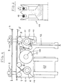
- FIG. 1 shows a winch carrier 1 which is suspended in a conventional manner on a support cable 4 by means of free-running carrier rollers such as the carrier roller pairs 2, 3 indicated here.
- the support cable 4 the diameter of which is approximately 30 mm, for example, is attached with its two ends to the end points of the route and is stretched between supports or freely.
- the system according to the invention also has a traction cable 5 which runs essentially parallel to the supporting cable 4 and which is likewise fastened with its ends in the vicinity of the end points of the route.
- This traction cable is guided on the winch carrier via a drive roller 6 , specifically after deflection via a first deflection roller 7 and then to the drive roller via a second deflection roller 8 .
- a guide roller 9 for this pull rope is arranged on the winch carrier.
- the traction cable runs between the deflection rollers 7 and 8 and the drive roller 6 in such a way that the parts located between 6 and 7 or 6 and 8 intersect, as a result of which a particularly large wrap angle is achieved on the drive roller 6 .
- the center planes of the deflection rollers 7 and 8 are each offset in the opposite direction with respect to the center plane of the drive roller 6 .
- the roller 6 is driven by a motor, not shown, the traction motor, via a gear indicated by 10 .
- the pull rope 5 runs on the roller 6 in a specially designed groove, as described with reference to FIG. 2 , whereby very good friction properties are achieved.
- the control of the drive of the roller 6 depending on the direction of rotation of this roller, causes the winch carrier to move along the supporting cable 4 in one direction or the other.
- FIG. 1 also schematically shows a cable winch which has a lifting roller 11 for lifting or lowering a lifting cable 12 .
- the lifting roller 11 is actuated by a drive motor, not shown, via a gear indicated by 13 .
- the hoisting rope 12 at the free end of which a load to be transported can be fastened, is guided after a first partial looping of the lifting roller 11 over an auxiliary roller 14 and passed by this back onto the roller 11 , from which it is looped over this lifting roller again two deflection rollers 15, 16 is wound on a storage roller 17 .
- Fig. 2 shows in radial section the shape of the lifting roller 11 used here, which has two parallel circumferential grooves.
- the hoist rope 12 is guided by the auxiliary roller 14 from one groove to the other. This results in a double wrap angle, which in connection with the one used Groove shape ensures an excellent frictional connection between the lifting rope and the lifting roller 11 and thus enables the lifting of heavy loads.
- the inner part of the grooves, which is in engagement with the rope, is here trapezoidal, the large base of the trapezoid being approximately equal to the rope diameter.
- the small base of the trapezium forms the bottom of this groove part, and the sides of the trapezium include an angle ⁇ of about 9-12 °.
- the height of the trapeze is larger than the diameter of the rope used.
- the drive roller 6 which has only one circumferential groove, has an analog groove profile as that shown in FIG. 2 .
- the storage roller 17 on which the hoist rope 13 is wound, is motor-operated via a gear indicated by 18 in order to wind back the corresponding rope length, in particular when the hoist rope moves upward.
- the deflection roller 16 is, for example, as shown in Fig. 1 , attached to a resiliently pivotable arm 19 , whereby the hoist rope between the rollers 11 and 17 remains tensioned even at a standstill.
- the drive motors for the rollers 6 , 11 and 17 are, for example, hydraulic motors which are actuated by a diesel engine 20 shown as a block.
- the individual drive units are not shown in Fig. 1 , since their execution is not the subject of the present invention. Also not shown are the control elements for the individual drives, which enable remote control of the winch and its movement along the suspension cable.
Landscapes
- Engineering & Computer Science (AREA)
- Mechanical Engineering (AREA)
- Carriers, Traveling Bodies, And Overhead Traveling Cranes (AREA)
Applications Claiming Priority (2)
| Application Number | Priority Date | Filing Date | Title |
|---|---|---|---|
| CH2937/94 | 1994-09-28 | ||
| CH293794A CH688313A5 (de) | 1994-09-28 | 1994-09-28 | Selbstfahrwinden-Anlage. |
Publications (1)
| Publication Number | Publication Date |
|---|---|
| EP0708054A1 true EP0708054A1 (fr) | 1996-04-24 |
Family
ID=4244988
Family Applications (1)
| Application Number | Title | Priority Date | Filing Date |
|---|---|---|---|
| EP95810610A Withdrawn EP0708054A1 (fr) | 1994-09-28 | 1995-09-28 | Installation avec treuil auto-déplaçable |
Country Status (2)
| Country | Link |
|---|---|
| EP (1) | EP0708054A1 (fr) |
| CH (1) | CH688313A5 (fr) |
Cited By (2)
| Publication number | Priority date | Publication date | Assignee | Title |
|---|---|---|---|---|
| CN115107810A (zh) * | 2022-05-07 | 2022-09-27 | 焦作煤业(集团)有限责任公司 | 一种架空乘人装置同步轮式防掉绳保护装置及预警方法 |
| CN115663679A (zh) * | 2017-11-22 | 2023-01-31 | 自然资源部第二海洋研究所 | 一种海洋科考作业设备高空滑轮机构 |
Citations (6)
| Publication number | Priority date | Publication date | Assignee | Title |
|---|---|---|---|---|
| DE185389C (fr) * | ||||
| FR516057A (fr) * | 1918-12-31 | 1921-04-13 | Karl Dittelbach | Grue à cable |
| CH497337A (de) * | 1970-03-17 | 1970-10-15 | Wyssen Jakob | Seilbahnkran |
| CH562751A5 (en) * | 1974-03-11 | 1975-06-13 | Schneider Kurt | Rope-supported travelling crane - has hydraulic system valves controlled by radio signals from ground level |
| EP0274554A1 (fr) * | 1987-01-14 | 1988-07-20 | Kozo Hirano | Système de transport par câbles aériens commandé par radio |
| FR2650580A3 (fr) * | 1989-08-04 | 1991-02-08 | Maes Joris | Palan manuel |
-
1994
- 1994-09-28 CH CH293794A patent/CH688313A5/de not_active IP Right Cessation
-
1995
- 1995-09-28 EP EP95810610A patent/EP0708054A1/fr not_active Withdrawn
Patent Citations (6)
| Publication number | Priority date | Publication date | Assignee | Title |
|---|---|---|---|---|
| DE185389C (fr) * | ||||
| FR516057A (fr) * | 1918-12-31 | 1921-04-13 | Karl Dittelbach | Grue à cable |
| CH497337A (de) * | 1970-03-17 | 1970-10-15 | Wyssen Jakob | Seilbahnkran |
| CH562751A5 (en) * | 1974-03-11 | 1975-06-13 | Schneider Kurt | Rope-supported travelling crane - has hydraulic system valves controlled by radio signals from ground level |
| EP0274554A1 (fr) * | 1987-01-14 | 1988-07-20 | Kozo Hirano | Système de transport par câbles aériens commandé par radio |
| FR2650580A3 (fr) * | 1989-08-04 | 1991-02-08 | Maes Joris | Palan manuel |
Cited By (4)
| Publication number | Priority date | Publication date | Assignee | Title |
|---|---|---|---|---|
| CN115663679A (zh) * | 2017-11-22 | 2023-01-31 | 自然资源部第二海洋研究所 | 一种海洋科考作业设备高空滑轮机构 |
| CN115663679B (zh) * | 2017-11-22 | 2023-06-16 | 自然资源部第二海洋研究所 | 一种海洋科考作业设备滑轮机构 |
| CN115107810A (zh) * | 2022-05-07 | 2022-09-27 | 焦作煤业(集团)有限责任公司 | 一种架空乘人装置同步轮式防掉绳保护装置及预警方法 |
| CN115107810B (zh) * | 2022-05-07 | 2024-04-05 | 焦作煤业(集团)有限责任公司 | 一种架空乘人装置同步轮式防掉绳保护装置及预警方法 |
Also Published As
| Publication number | Publication date |
|---|---|
| CH688313A5 (de) | 1997-07-31 |
Similar Documents
| Publication | Publication Date | Title |
|---|---|---|
| DE2457864C2 (de) | Laufkatzenkran | |
| DE2835294B2 (de) | Seilzugvorrichtung | |
| DE69006700T2 (de) | An einem Hochseil hängender Wagen zum Transport schwerer Lasten. | |
| DE2523345C2 (de) | Aufzug | |
| EP0773074B1 (fr) | Accumulateur de bandes horizontal | |
| DE102012100791A1 (de) | Zugmittel-Windenvorrichtung | |
| EP0161437B1 (fr) | Grue à câble | |
| EP0388708B1 (fr) | Accumulateur de bandes pour l'opération continue de lignes de laminage | |
| CH688313A5 (de) | Selbstfahrwinden-Anlage. | |
| DE2201548C3 (de) | Seilwinde für unbegrenzten Seildurchlauf | |
| DE2622165C2 (de) | Doppeltrommelwinde | |
| DE1221413B (de) | Seilwinde mit zwei Treibscheiben und einer Speichertrommel | |
| AT385494B (de) | Kabelkranwagen | |
| DE3443191C2 (de) | Stoßschutzeinrichtung für das Abbremsen von Schiffen in Schleusenanlagen | |
| DE3726997C2 (de) | Brückenkran mit gewölbter Brücke | |
| DE4001680C1 (en) | Rope haulage trolley - has rotating bearer rope pulley located between two bearer rope rollers | |
| DE4003053C2 (fr) | ||
| DE613113C (de) | Kranfahrwerk fuer Lauf-, Bock- und Brueckenkrane, deren Laufrollen in ihrer Achsenrichtung ausreichend Spielraum haben, mit Antrieb durch Drahtseile | |
| DE29816005U1 (de) | Schachtförderanlage mit Trommelwinde | |
| DE1756363B2 (de) | Treibscheibenwinde | |
| AT409371B (de) | Seilreiter für ein tragseil und ein zugseil aufweisende seilkräne | |
| CH684088A5 (de) | Seilkran. | |
| CH619427A5 (en) | Drive arrangement for a rope run around a drivable deflection pulley | |
| DE4010833A1 (de) | Aus mehreren leiterabschnitten gebildeter schraegaufzug | |
| DE513976C (de) | Reibungstrommel |
Legal Events
| Date | Code | Title | Description |
|---|---|---|---|
| PUAI | Public reference made under article 153(3) epc to a published international application that has entered the european phase |
Free format text: ORIGINAL CODE: 0009012 |
|
| AK | Designated contracting states |
Kind code of ref document: A1 Designated state(s): AT DE FR IT SE |
|
| STAA | Information on the status of an ep patent application or granted ep patent |
Free format text: STATUS: THE APPLICATION IS DEEMED TO BE WITHDRAWN |
|
| 18D | Application deemed to be withdrawn |
Effective date: 19961025 |