EP0708231A1 - Vorrichtung zur Steuerung der Ladeluftkühlungkraft einer Brennkraftmaschine - Google Patents
Vorrichtung zur Steuerung der Ladeluftkühlungkraft einer Brennkraftmaschine Download PDFInfo
- Publication number
- EP0708231A1 EP0708231A1 EP95116263A EP95116263A EP0708231A1 EP 0708231 A1 EP0708231 A1 EP 0708231A1 EP 95116263 A EP95116263 A EP 95116263A EP 95116263 A EP95116263 A EP 95116263A EP 0708231 A1 EP0708231 A1 EP 0708231A1
- Authority
- EP
- European Patent Office
- Prior art keywords
- cylinder
- shutter
- actuating
- release
- charge air
- Prior art date
- Legal status (The legal status is an assumption and is not a legal conclusion. Google has not performed a legal analysis and makes no representation as to the accuracy of the status listed.)
- Withdrawn
Links
- 238000001816 cooling Methods 0.000 title claims description 20
- 230000003213 activating effect Effects 0.000 claims abstract description 5
- 230000000903 blocking effect Effects 0.000 claims description 7
- 230000004913 activation Effects 0.000 claims description 5
- 230000009849 deactivation Effects 0.000 claims description 3
- 101001017827 Mus musculus Leucine-rich repeat flightless-interacting protein 1 Proteins 0.000 description 3
- 230000000694 effects Effects 0.000 description 3
- 240000008042 Zea mays Species 0.000 description 1
- 230000000295 complement effect Effects 0.000 description 1
Images

Classifications
-
- F—MECHANICAL ENGINEERING; LIGHTING; HEATING; WEAPONS; BLASTING
- F02—COMBUSTION ENGINES; HOT-GAS OR COMBUSTION-PRODUCT ENGINE PLANTS
- F02B—INTERNAL-COMBUSTION PISTON ENGINES; COMBUSTION ENGINES IN GENERAL
- F02B29/00—Engines characterised by provision for charging or scavenging not provided for in groups F02B25/00, F02B27/00 or F02B33/00 - F02B39/00; Details thereof
- F02B29/04—Cooling of air intake supply
- F02B29/0406—Layout of the intake air cooling or coolant circuit
- F02B29/0418—Layout of the intake air cooling or coolant circuit the intake air cooler having a bypass or multiple flow paths within the heat exchanger to vary the effective heat transfer surface
-
- F—MECHANICAL ENGINEERING; LIGHTING; HEATING; WEAPONS; BLASTING
- F02—COMBUSTION ENGINES; HOT-GAS OR COMBUSTION-PRODUCT ENGINE PLANTS
- F02D—CONTROLLING COMBUSTION ENGINES
- F02D41/00—Electrical control of supply of combustible mixture or its constituents
- F02D41/0002—Controlling intake air
- F02D41/0007—Controlling intake air for control of turbo-charged or super-charged engines
-
- Y—GENERAL TAGGING OF NEW TECHNOLOGICAL DEVELOPMENTS; GENERAL TAGGING OF CROSS-SECTIONAL TECHNOLOGIES SPANNING OVER SEVERAL SECTIONS OF THE IPC; TECHNICAL SUBJECTS COVERED BY FORMER USPC CROSS-REFERENCE ART COLLECTIONS [XRACs] AND DIGESTS
- Y02—TECHNOLOGIES OR APPLICATIONS FOR MITIGATION OR ADAPTATION AGAINST CLIMATE CHANGE
- Y02T—CLIMATE CHANGE MITIGATION TECHNOLOGIES RELATED TO TRANSPORTATION
- Y02T10/00—Road transport of goods or passengers
- Y02T10/10—Internal combustion engine [ICE] based vehicles
- Y02T10/12—Improving ICE efficiencies
Definitions
- the invention relates to a device for controlling the temperature of the charge air of a heat engine, in particular of a vehicle drive motor, comprising cooling means interposed between a charge air compressor and the air inlet of the engine, and switching means suitable for directing a flow of air coming from the compressor, as a function of its temperature, either towards said cooling means, or directly towards the inlet of the engine through a pipe bypass, the switching means comprising a movable shutter, and an elastic actuating element urging the movable shutter to a first position for which the compressor communicates with the bypass line, associated with an actuating cylinder capable of forcing the shutter, against the action of the elastic actuating element, in a second position for which the compressor communicates with the cooling means ement.
- the charge air does not enter the engine at too high a pressure. For this reason, it may be useful to pass the air through the cooling means to undergo a pressure drop there, even when cooling is no longer necessary.
- the object of the invention is to avoid excessive temperature of the charge air in the event of failure of the supply to the actuating cylinder, or excessive pressure of the charge air, and more generally to maintain the shutter in its second position when circumstances require, even if the actuating cylinder is deactivated.
- the invention relates in particular to a device of the kind defined in the introduction, and provides that it comprises at least one elastic blocking element associated with a stop element and with a release cylinder, the elastic blocking element urging the stop in a first position that it can only reach when the shutter is in its second position and where it prohibits the return of the latter in its first position, and the release cylinder being adapted to force the stop element , against the action of the elastic blocking element, in a second position in which it releases the movement of the shutter.
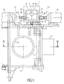
- the switching device illustrated comprises in a known manner a flap 1 pivotally mounted in a switching box 2, around a vertical axis 3, so as to be located substantially in a variable vertical plane.
- the interior of the housing 2 defines a chamber 4 which communicates with the exterior by three inlet / outlet connections, namely an inlet connection (not shown) receiving the compressed and heated air coming from a turbo-compressor of charge air, and two outlet connections 5 and 6 by which the air can exit respectively to pass through a bypass line not shown leading it directly, without being cooled, to the air intake of the engine, and to pass through a cooling radiator before reaching the engine inlet.
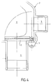
- the shutter 1 can pivot by an angle of 90 ° between a position, shown in FIG. 1, where it closes the outlet fitting 5, forcing the charge air to pass through the fitting 6 and through the cooling radiator, and a position illustrated in FIG. 4, where, on the contrary, it closes the connector 6, the air then leaving through the connector 5 and not being cooled.
- the flap 1 is driven by a pneumatic cylinder 7 associated with a non return spring.
- the jack 7 comprises a fixed cylinder 8 and a sliding rod 9 at the free end of which is mounted a connecting piece 10 which is connected to a horizontal lever 11 integral with the flap 1, so that the latter takes its first position when the rod 9 is retracted ( Figures 1 and 2) and its second position when the rod 9 is extended ( Figures 3 and 4).
- the rod is in the retracted position when the jack is activated, and the return spring biases it towards its extended position.
- the invention provides two release cylinders 12 and 13, associated with respective opposing springs called blocking, to prevent, in specific circumstances, the rod 9 of the actuating cylinder to come out under the action of the corresponding spring, said spring actuation.
- the pneumatic cylinders 12 and 13 comprise respective cylinders 14 and 15 and respective rods 16 and 17.
- the latter cooperate with the connecting piece 10 which has for these purposes a particular configuration.
- the part 10 has a generally rectangular parallelepiped shape provided with an upper face 18 and a lower face 19 horizontal, with a rear face 20 facing the cylinder 8, with a front face 21 opposite the rear face and with two lateral faces 22 and 23, the faces 20 to 23 being vertical.
- the lever 11 is opposite the underside 19.
- the part has a large recess 24 which opens into the faces 18 and 21. Between this recess on the one hand and the faces 19, 22 and 23 on the other hand, there remain blades relatively thin material 25, 26 and 27 respectively.
- the rods 16 and 17 of the jacks 12 and 13 have the same horizontal axis 28 perpendicular to the horizontal axis of the rod 9.
- the rod 17 of the cylinder 13 is shown in Figures 1 to 3 in the retracted position.
- the corresponding stop piece 30 is then set back from the plane containing the lateral face 23, turned towards the body 15, of the connecting piece 10.
- the rod 9 of the jack 7 can then pass from its retracted position (FIGS. 1 and 2 ) in its extended position (FIG. 3) without the part 30 hindering the movement of the part 10.
- the rod 16 of the jack 12 is in its extended position and the corresponding stop piece 29 crosses the plane of the lateral face 22 of the piece 10 turned towards the body 14 of the same jack.
- the rod can therefore take this position only when that 9 of the cylinder 7 is retracted.
- the branch 26 of the part 10 then comes to bear, by the front face 21, on the cylindrical lateral face 33 of the part 31 to prevent the rod 9 from coming out. If the rod 16 tends to come out while the rod 9 is itself out, the end face 31 of the part 29 abuts on the lateral face 22 of the part 10, which limits the movement of the rod 16 , as shown in Figure 3.
- the part 10 being symmetrical, and the rods 16 and 17 and the parts 29 and 30 symmetrical to one another, with respect to the vertical plane containing the axis of the rod 9, the modes of action set out above for each of the parts 29 and 30 are also valid for each other.
- the return spring associated with each cylinder tends to cause the rod to come out against the pneumatic action of the cylinder.
- the pressure in the pneumatic cylinder supply circuit is zero and the cylinders are deactivated.
- the pressure required to activate the cylinders for example 5 bars, is established before the temperature and the pressure of the charge air have reached the aforementioned thresholds.
- the rods of the auxiliary cylinders 12 and 13 are then retracted, allowing the rod of the main cylinder 7 to exit under the effect of the actuating spring.
- the jacks 7 and 12 are activated and deactivated respectively so as to retract the rod 9 and allow the rod 16 to exit under the effect the corresponding locking spring.
- the jack 7 is deactivated but the part 31, forming a stop for the part 10, prevents the rod 9 from coming out under the effect of the actuating spring, so that the charge air continues to be sent to the cooling radiator.
- the cylinder 13 is deactivated and the corresponding spring brings out the rod 17, which comes in a position symmetrical to that illustrated for the rod 16 in Figures 1 and 2 , the part 30 forming a stop for the free end of the branch 27 of the part 10. If subsequently the temperature of the charge air is brought below 50 ° C. while its pressure remains greater than 1, 4 bar, rod 16 of actuator 12 retracts but the rod 9 of actuator 7 is nevertheless prevented from exiting by the part 30.
Landscapes
- Engineering & Computer Science (AREA)
- Chemical & Material Sciences (AREA)
- Combustion & Propulsion (AREA)
- Mechanical Engineering (AREA)
- General Engineering & Computer Science (AREA)
- Physics & Mathematics (AREA)
- Thermal Sciences (AREA)
- Supercharger (AREA)
- Cooling, Air Intake And Gas Exhaust, And Fuel Tank Arrangements In Propulsion Units (AREA)
Applications Claiming Priority (2)
| Application Number | Priority Date | Filing Date | Title |
|---|---|---|---|
| FR9412628A FR2726039B1 (fr) | 1994-10-21 | 1994-10-21 | Dispositif de commande du refroidissement de l'air de suralimentation d'un moteur thermique |
| FR9412628 | 1994-10-21 |
Publications (1)
| Publication Number | Publication Date |
|---|---|
| EP0708231A1 true EP0708231A1 (de) | 1996-04-24 |
Family
ID=9468097
Family Applications (1)
| Application Number | Title | Priority Date | Filing Date |
|---|---|---|---|
| EP95116263A Withdrawn EP0708231A1 (de) | 1994-10-21 | 1995-10-16 | Vorrichtung zur Steuerung der Ladeluftkühlungkraft einer Brennkraftmaschine |
Country Status (4)
| Country | Link |
|---|---|
| US (1) | US5649516A (de) |
| EP (1) | EP0708231A1 (de) |
| KR (1) | KR960015990A (de) |
| FR (1) | FR2726039B1 (de) |
Cited By (1)
| Publication number | Priority date | Publication date | Assignee | Title |
|---|---|---|---|---|
| EP1270895A1 (de) | 2001-06-29 | 2003-01-02 | Ford Global Technologies, Inc., A subsidiary of Ford Motor Company | Ladelufttemperaturkontrolle für Motoren mit Ladeluftkühler |
Families Citing this family (15)
| Publication number | Priority date | Publication date | Assignee | Title |
|---|---|---|---|---|
| US8215292B2 (en) | 1996-07-17 | 2012-07-10 | Bryant Clyde C | Internal combustion engine and working cycle |
| US6951211B2 (en) | 1996-07-17 | 2005-10-04 | Bryant Clyde C | Cold air super-charged internal combustion engine, working cycle and method |
| US7281527B1 (en) * | 1996-07-17 | 2007-10-16 | Bryant Clyde C | Internal combustion engine and working cycle |
| US7222614B2 (en) | 1996-07-17 | 2007-05-29 | Bryant Clyde C | Internal combustion engine and working cycle |
| US7178492B2 (en) | 2002-05-14 | 2007-02-20 | Caterpillar Inc | Air and fuel supply system for combustion engine |
| US6688280B2 (en) | 2002-05-14 | 2004-02-10 | Caterpillar Inc | Air and fuel supply system for combustion engine |
| US7201121B2 (en) | 2002-02-04 | 2007-04-10 | Caterpillar Inc | Combustion engine including fluidically-driven engine valve actuator |
| US7191743B2 (en) | 2002-05-14 | 2007-03-20 | Caterpillar Inc | Air and fuel supply system for a combustion engine |
| US7252054B2 (en) | 2002-05-14 | 2007-08-07 | Caterpillar Inc | Combustion engine including cam phase-shifting |
| US7152588B2 (en) * | 2002-10-15 | 2006-12-26 | International Engine Intellectual Property Company, Llc | Intercooler bypass |
| US6868840B2 (en) * | 2003-06-05 | 2005-03-22 | Detroit Diesel Corporation | Charged air intake system for an internal combustion engine |
| US6883320B2 (en) * | 2003-07-08 | 2005-04-26 | G. W. Lisk Company, Inc. | Control system regulating air flow to engine intake |
| US20060082682A1 (en) * | 2004-10-15 | 2006-04-20 | Hoodman Corporation | Camera LCD screen viewing device |
| US20070199319A1 (en) * | 2006-02-28 | 2007-08-30 | Bender Burnell L | System and method for controlling engine charge air temperature |
| DE102011078457B4 (de) * | 2011-06-30 | 2013-05-08 | Ford Global Technologies, Llc | Verfahren zum Betreiben einer Brennkraftmaschine mit Ladeluftkühler |
Citations (2)
| Publication number | Priority date | Publication date | Assignee | Title |
|---|---|---|---|---|
| EP0080983A2 (de) * | 1981-12-01 | 1983-06-08 | Ab Volvo | Verbrennungsluftzufuhrvorrichtung für aufgeladene Brennkraftmaschine mit Ladeluftkühlung |
| EP0602348A1 (de) * | 1992-12-12 | 1994-06-22 | MAN Nutzfahrzeuge Aktiengesellschaft | Verfahren zur Regelung der Ladelufttemperatur, sowie Vorrichtung zu dessen Durchführung |
Family Cites Families (4)
| Publication number | Priority date | Publication date | Assignee | Title |
|---|---|---|---|---|
| GB1255956A (en) * | 1968-02-02 | 1971-12-08 | Covrad Ltd Formerly Known As C | Means for regulating the temperature of air passing from an air compressor to an internal combustion engine |
| US3712282A (en) * | 1971-01-22 | 1973-01-23 | Teledyne Ind | Temperature control system for supercharged internal combustion engine |
| SE460304B (sv) * | 1981-12-01 | 1989-09-25 | Volvo Ab | Anordning foer tillfoersel av foerbraenningsluft till cylindrarna i en foerbraenningsmotor |
| AT393539B (de) * | 1988-09-02 | 1991-11-11 | Steyr Daimler Puch Ag | Brennkraftmaschine mit einem aufladeaggregat fuer die ladeluft |
-
1994
- 1994-10-21 FR FR9412628A patent/FR2726039B1/fr not_active Expired - Fee Related
-
1995
- 1995-10-16 EP EP95116263A patent/EP0708231A1/de not_active Withdrawn
- 1995-10-19 US US08/545,281 patent/US5649516A/en not_active Expired - Fee Related
- 1995-10-20 KR KR1019950036501A patent/KR960015990A/ko not_active Withdrawn
Patent Citations (2)
| Publication number | Priority date | Publication date | Assignee | Title |
|---|---|---|---|---|
| EP0080983A2 (de) * | 1981-12-01 | 1983-06-08 | Ab Volvo | Verbrennungsluftzufuhrvorrichtung für aufgeladene Brennkraftmaschine mit Ladeluftkühlung |
| EP0602348A1 (de) * | 1992-12-12 | 1994-06-22 | MAN Nutzfahrzeuge Aktiengesellschaft | Verfahren zur Regelung der Ladelufttemperatur, sowie Vorrichtung zu dessen Durchführung |
Cited By (1)
| Publication number | Priority date | Publication date | Assignee | Title |
|---|---|---|---|---|
| EP1270895A1 (de) | 2001-06-29 | 2003-01-02 | Ford Global Technologies, Inc., A subsidiary of Ford Motor Company | Ladelufttemperaturkontrolle für Motoren mit Ladeluftkühler |
Also Published As
| Publication number | Publication date |
|---|---|
| US5649516A (en) | 1997-07-22 |
| KR960015990A (ko) | 1996-05-22 |
| FR2726039A1 (fr) | 1996-04-26 |
| FR2726039B1 (fr) | 1996-12-13 |
Similar Documents
| Publication | Publication Date | Title |
|---|---|---|
| EP0708231A1 (de) | Vorrichtung zur Steuerung der Ladeluftkühlungkraft einer Brennkraftmaschine | |
| EP2414242B1 (de) | Betankungsvorrichtung für trägerraketenantrieb | |
| FR2677909A1 (fr) | Machine-outil, en particulier scie a moteur a chaine. | |
| EP0216710B1 (de) | Mehrkopfspannvorrichtung mit einer einzelnen Fernbetätigung | |
| FR2634619A1 (fr) | Dispositif de commande pour une tondeuse a gazon actionnee par un conducteur a pied | |
| FR2899641A1 (fr) | Regulateur de papillon des gaz pour une machine de compactage par vibration. | |
| FR2634508A2 (fr) | Verrou a commande electrique complete par une commande mecanique accessible depuis l'interieur du local | |
| FR2611549A3 (fr) | Cisaille motorisee auto-alimentee | |
| CA2429160C (fr) | Dispositif de decharge brusque d'air | |
| EP0725709B1 (de) | Schraubenschlüssel | |
| EP1364891A1 (de) | Belüftungsvorrichtung durch plötzliches Ablassen von Druckluft mit einem verbesserten Auswerfenrohr | |
| EP1649478B1 (de) | Dreheingriffs-verriegelungsmechanismus für automatische sicherheitsabtrennung | |
| FR2510059A1 (fr) | Mecanisme de manoeuvre d'aiguillages de voies ferrees du " type cale " | |
| EP1498331B1 (de) | Teleskopische Scheinwerfer-Reinigungseinrichtung für ein Kraftfahrzeug | |
| WO2021063618A1 (fr) | Dispositif de nettoyage d'un système optique | |
| EP0989245B1 (de) | Steuervorrichtung für eine Erdbewegungsmaschine | |
| EP0153253B1 (de) | Hydraulisches Hochdruckwegeventil mit mechanisch steuerbarem Auslassventil | |
| EP0778111A1 (de) | Notausschaltvorrichtung für Roboter | |
| FR2821010A1 (fr) | Dispositif de commande du mecanisme d'obturation d'une buse d'injection dans le domaine de l'injection des matieres plastiques et silicones | |
| FR2705741A1 (fr) | Dispositif de commande pneumatique assisté. | |
| FR2487802A1 (fr) | Dispositif de commande d'un treuil | |
| EP4628240A1 (de) | Widerstandsschweissvorrichtung mit fester elektrode und beweglicher elektrode zwischen arbeitsposition und zwei verschiedenen ruhepositionen | |
| EP0867594A1 (de) | Automatische Bremsvorrichtung für einen Elektromotor, der ein drehendes Teil antreibt | |
| EP0111433A1 (de) | Verteilvorrichtung einer fahrbaren Sprühvorrichtung für eine Flüssigkeit zur Behandlung von Pflanzen | |
| FR2847641A1 (fr) | Vanne de regulation a tiroir a au moins deux voies d'un nouveau type |
Legal Events
| Date | Code | Title | Description |
|---|---|---|---|
| PUAI | Public reference made under article 153(3) epc to a published international application that has entered the european phase |
Free format text: ORIGINAL CODE: 0009012 |
|
| AK | Designated contracting states |
Kind code of ref document: A1 Designated state(s): DE ES GB IT SE |
|
| 17P | Request for examination filed |
Effective date: 19960826 |
|
| GRAG | Despatch of communication of intention to grant |
Free format text: ORIGINAL CODE: EPIDOS AGRA |
|
| STAA | Information on the status of an ep patent application or granted ep patent |
Free format text: STATUS: THE APPLICATION HAS BEEN WITHDRAWN |
|
| 17Q | First examination report despatched |
Effective date: 19970911 |
|
| 18W | Application withdrawn |
Withdrawal date: 19970922 |