EP0708344A2 - Messsystem zur berührungslosen Messung des Vertikal- und Horizontalabstandes zwischen Fahrzeug und Schiene - Google Patents
Messsystem zur berührungslosen Messung des Vertikal- und Horizontalabstandes zwischen Fahrzeug und Schiene Download PDFInfo
- Publication number
- EP0708344A2 EP0708344A2 EP95114427A EP95114427A EP0708344A2 EP 0708344 A2 EP0708344 A2 EP 0708344A2 EP 95114427 A EP95114427 A EP 95114427A EP 95114427 A EP95114427 A EP 95114427A EP 0708344 A2 EP0708344 A2 EP 0708344A2
- Authority
- EP
- European Patent Office
- Prior art keywords
- measuring system
- measuring
- rail
- vertical
- detector
- Prior art date
- Legal status (The legal status is an assumption and is not a legal conclusion. Google has not performed a legal analysis and makes no representation as to the accuracy of the status listed.)
- Granted
Links
- 238000005259 measurement Methods 0.000 claims abstract description 18
- 238000006073 displacement reaction Methods 0.000 claims abstract description 7
- 230000003287 optical effect Effects 0.000 claims description 9
- 238000001514 detection method Methods 0.000 claims description 2
- 239000000523 sample Substances 0.000 claims description 2
- 238000011156 evaluation Methods 0.000 claims 2
- 239000000443 aerosol Substances 0.000 claims 1
- 230000015572 biosynthetic process Effects 0.000 claims 1
- 230000005484 gravity Effects 0.000 claims 1
- 238000003384 imaging method Methods 0.000 claims 1
- 239000007788 liquid Substances 0.000 claims 1
- 238000012544 monitoring process Methods 0.000 claims 1
- 230000003534 oscillatory effect Effects 0.000 claims 1
- 230000000737 periodic effect Effects 0.000 claims 1
- 230000001360 synchronised effect Effects 0.000 claims 1
- 238000000034 method Methods 0.000 description 10
- 238000013519 translation Methods 0.000 description 4
- 230000007704 transition Effects 0.000 description 3
- 238000007096 Glaser coupling reaction Methods 0.000 description 1
- 238000000149 argon plasma sintering Methods 0.000 description 1
- 230000009194 climbing Effects 0.000 description 1
- 238000012937 correction Methods 0.000 description 1
- 230000009189 diving Effects 0.000 description 1
- 238000012423 maintenance Methods 0.000 description 1
- 238000004519 manufacturing process Methods 0.000 description 1
- 238000000691 measurement method Methods 0.000 description 1
- 238000012634 optical imaging Methods 0.000 description 1
- 238000005096 rolling process Methods 0.000 description 1
- 230000001629 suppression Effects 0.000 description 1
- 239000000725 suspension Substances 0.000 description 1
Images


Classifications
-
- B—PERFORMING OPERATIONS; TRANSPORTING
- B61—RAILWAYS
- B61K—AUXILIARY EQUIPMENT SPECIALLY ADAPTED FOR RAILWAYS, NOT OTHERWISE PROVIDED FOR
- B61K9/00—Railway vehicle profile gauges; Detecting or indicating overheating of components; Apparatus on locomotives or cars to indicate bad track sections; General design of track recording vehicles
- B61K9/08—Measuring installations for surveying permanent way
-
- G—PHYSICS
- G01—MEASURING; TESTING
- G01B—MEASURING LENGTH, THICKNESS OR SIMILAR LINEAR DIMENSIONS; MEASURING ANGLES; MEASURING AREAS; MEASURING IRREGULARITIES OF SURFACES OR CONTOURS
- G01B11/00—Measuring arrangements characterised by the use of optical techniques
- G01B11/02—Measuring arrangements characterised by the use of optical techniques for measuring length, width or thickness
- G01B11/026—Measuring arrangements characterised by the use of optical techniques for measuring length, width or thickness by measuring distance between sensor and object
Definitions
- the invention relates to a triangulation measuring system with a horizontal plane for contactless detection of the vertical and horizontal distances from a moving reference system against a cylindrical shaped object.
- a part of this is the measurement of distances of the rail from a reference point, e.g. B. from an axle bearing of a measuring vehicle.
- the principle of optical triangulation is mainly used.
- the British Railways measure the horizontal distance in such a way that each rail is illuminated from above and a camera is directed from above onto the rail in question. Ideally, the driving surface is light and the inside flank is dark. The horizontal distance is calculated from the position of the image of the light-dark transition on the camera detector (Lewis RB: Track-recording techniques used on British Rail. IEE Proceedings, Vol. 131, Pt. B, No. 3 May 1984, p. 73-81).
- the components are attached to the bogie frame of the measurement vehicle.
- the primary suspension between the axle bearings and the bogie frame generates a diving and rolling movement of a magnitude when driving, which would make the probing light spot go nowhere.
- the projector therefore contains a rotating mirror, which receives its control variables via a computer from an auxiliary system which consists of four displacement transducers mounted parallel to the primary springs (Esveld, C .: Modern railway track, MRT-Productions Duisburg (1989), p. 292-294).
- European patent application 0 461 628 describes a triangulation system which is integrated in a wheel disc.
- the wheel rim is provided with appropriate openings for beam exit and entry.
- the horizontal distances to the rail flank are measured in time with the wheel rotation at the moment when the opening is at the level of the rail flank.
- the vertical distance is not measured at all in the known measuring methods. Instead, the value of the radius of the equivalent cylindrical wheel is taken as a rough approximation for the vertical distance. It is disregarded that in reality wheel profiles with variable radius, ie with taper or wear profile, must always be used so that one-sided start-up and derailment by climbing do not occur. Such a constant radius cannot be used as a tracking signal for the horizontal scanning of an orthogonally tracking scanning will. Further disadvantages of the known measuring methods lie in the inhomogeneous light scattering, in the non-constant optical imaging scale and in the incomplete suppression of stray light.
- the object of the invention is to be able to measure the horizontal distance and the vertical distance between the vehicle and the rail at the same time - without falsification by transverse movements - at high speeds with great accuracy.
- the advantage lies particularly in the simultaneous measurement of the horizontal and vertical distance between the rail and a reference system on a measuring vehicle without being falsified by the transverse movements of the wheelset run.
- the feature of claim 13 guarantees the maintenance of a high measuring accuracy with long measuring times even in heavily polluted surroundings.
- a scanning light spot A is set by the light source Q at an angle ⁇ against the normal.
- Fixed to the light source Q is a camera K consisting of lens L and detector D, the optical axis of which is directed against the normal of F at an angle ⁇ .
- This maps A to BA on the detector level DE. If the surface element F is now shifted into the position F ', a new scanning light spot A' is created, which is shifted in the y direction compared to the old one. A 'is mapped from the camera to BA' on DE.
- the difference ⁇ between these two positions is proportional to the original displacement d of the surface element, the proportionality factor being determined exclusively by the basic distance g, the angles ⁇ and ⁇ and the optical magnification of the camera system.
- the limits of this measuring principle are also clear from FIG. 1.
- the surface element F must not be inclined or curved in the y-direction because the contact point progresses from A to A 'in the y-direction.
- the distance can only be changed in the z direction if the surface element is inclined and curved in the x direction. This triangulation principle cannot therefore be used if the surface element F is curved in the x direction and the change in distance has an x component.
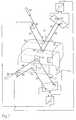
- the vertical triangulation TV is shown in the upper part of FIG. 2 and the horizontal triangulation TH is shown in the lower part.
- a part of a rail head SK in two different positions (translation in the x and z directions) is drawn as the measurement object, with the approximately horizontal contact surface piece FH and the approximately vertical contact surface piece FV.
- the area element FH is considered.
- the illuminating beam BV emanating from the light source QV strikes it at the angle ⁇ against the normal in the middle.
- the light is reflected at the angle ⁇ , forms the beam RV and hits the detector DV at point P1.
- the rail head SK now carries out a translation, which means that FH changes into FH '.
- the extension of the beam BV would no longer hit the surface element FH 'in the center. Therefore, the scanning beam BV has to be shifted parallel to the translation component in the y direction, becomes the beam BV 'and hits the surface element FH' again in the middle.
- the scattered / reflected beam RV 'in turn reaches the detector at the angle ⁇ against the normal at point P2.
- the electrical signal of the detector DV corresponds to a constant of the vertical position of the object. Therefore the difference signal of the detector corresponds to the vertical displacement component.
- the second surface element FV of the measurement object is now considered. It is converted from the SK into the element FV '.
- the light source QH generates a light spot on the center of the surface element FV with a light beam BH at the angle ⁇ against the normal and this light is imaged on the detector DH as a beam RH at the angle ⁇ against the normal at the point P3.
- the surface element FV is converted into the element FV 'by the object shift.
- the beam BH must now be shifted by the translation component in the z direction, becomes beam BH 'and hits the surface element FV' again in the middle.
- the reflected beam RH ' reaches the detector DH at point P4.
- the signal of the detector DH corresponds to a constant of the horizontal position of the object. Therefore, the detector differential signal corresponds to the horizontal displacement component.
- Optical translators are tracking elements that shift a light beam or a corresponding beam path in proportion to an electronic input signal.
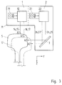
- FIGS. 3 to 5 An embodiment of this invention in the form of a measuring head is shown in FIGS. 3 to 5.
- the measuring head M anchored via a support to two opposite axle bearings contains the vertical measuring head 1 and the horizontal measuring head 2.
- the vertical measuring head 1 consists of the light source 11, the beam translator 12, and the triangulation camera 13 with the detector 18 and the transducer 19.
- the scanning beam 14 is emitted, which strikes the rail S in the surface element A1, is reflected, reaches the beam 15 as the camera 13 onto the detector 18, which outputs the position signal a1 via a converter circuit 19.
- the scanning beam shifts along the line 16, hits the rail S' in A1 ', is converted into the beam 17 by reflection and reaches the detector 18, the signal a2 being generated.
- the horizontal measuring head 2 consists of the light source 21, the beam translator 22, and the triangulation camera 23 with the detector 28 and the transducer 29.
- the scanning beam 24 is emitted, which strikes the rail S after the deflection by the deflection element 3 in the surface element A2 reflects and arrives as a beam 25 in the camera 23 on the detector 28, which outputs the position signal a3 via a converter circuit 29.
- the scanning beam shifts along the line 26, hits the rail S' in A2 ', is converted into the beam 27 by reflection and reaches the detector at point 28 and generates the signal a4.
- control input of the vertical translator 12 receives the position signal of the horizontal output a4 or a3 and vice versa
- the control input of the horizontal translator 22 receives the position signal of the vertical output a2 or a1.
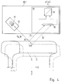
- FIG. 1 An embodiment of an optomechanical beam translator is shown in FIG.
- the beam generated by the light source 11, 21 falls on the central axis of a mirror 30, which coincides with the axis of a galvanometer unit 31. This axis lies in the focal plane of a lens 32.
- the galvanometer input 33 By actuating the galvanometer input 33 with a corresponding position signal, the mirror is rotated into a specific angular position, and the light beam always reaches that parallel to the optical axis Probe surface S.
- the displacement of the beam is proportional to the difference between two control signals 33.
Landscapes
- Engineering & Computer Science (AREA)
- Mechanical Engineering (AREA)
- Physics & Mathematics (AREA)
- General Physics & Mathematics (AREA)
- Length Measuring Devices By Optical Means (AREA)
- Measurement Of Optical Distance (AREA)
Abstract
Description
- Die Erfindung betrifft ein Triangulationsmeßsystem mit horizontaler Ebene zur berührungslosen Erfassung des Vertikal- und des Horizontalabstandes von einem bewegten Bezugssystem gegen ein zylindrisch geformtes Objekt.
- Zur Sicherung des Eisenbahnbetriebes ist es erforderlich, Gleislage, Fahrdrahtlage, Radstellung u. a. in gewissen zeitlichen Inspektionsintervallen zu messen, um bei unzulässigen Abweichungen Korrekturen an den Gleisen, Fahrleitungen und Fahrzeugen vornehmen zu können.
- Eine Teilaufgabe hiervon ist die Messung von Abständen der Schiene von einem Bezugspunkt, z. B. von einem Achslager eines Meßfahrzeuges.
- Alle bekannten Meßverfahren zur Messung von Abständen an Schienen sind optische Verfahren.
- Dabei wird überwiegend das Prinzip der optischen Triangulation angewendet.
- Die British Railways messen den Horizontalabstand derart, daß jede Schiene von oben beleuchtet wird und eine Kamera von oben auf die betreffende Schiene gerichtet ist. Im Idealfall ist die Fahrfläche hell und die Innenflanke ist dunkel. Der Horizontalabstand wird aus der Position des Bildes des Hell-Dunkel-Überganges auf dem Kameradetektor berechnet (Lewis R. B.: Track-recording techniques used on British Rail. IEE Proceedings, Vol. 131, Pt. B, No. 3 Mai 1984, S. 73 - 81).
- In ZEV Glasers Annalen (1977) Heft 8/9 S. 391 - 394 beschreibt R. Jenzer "Eine Methode zur Erfassung der dynamischen Spurspielmeßgrößen an Schienenfahrzeugen (Radstellungsmessung)".
- Bei der Meßmethode der Nederlandse Spoorwegen sind die Komponenten am Drehgestellrahmen des Meßfahrzeuges befestigt. Die zwischen Achslagern und Drehgestellrahmen vorhandene Primärfederung erzeugt aber beim Fahren eine Tauch- und Rollbewegung von einer Größenordnung, die den Antastlichtfleck ins Leere gehen ließe. Daher enthält der Projektor einen Drehspiegel, der seine Steuer-Regelgrößen über einen Rechner von einem Hilfssystem erhält, welches aus vier parallel zu den Primärfedern angebrachten Wegaufnehmern besteht (Esveld, C.: Modern railway track, MRT-Productions Duisburg (1989), S. 292 - 294).
- Bei einem bekannten Verfahren zur automatischen Gleisvermessung ist auch die Messung im Weichenbereich möglich. Der untere Teil des Meßkopfes befindet sich dabei im Spurkranzschatten. Die optische Antastung erfolgt horizontal (Schuller, R.: Verfahren zur automatischen Gleisvermessung. ETR 29 (1980), S. 433 - 438).
- In der Europäischen Patentanmeldung 0 461 628 wird ein Triangulationssystem beschrieben, das in einer Radscheibe integriert ist. Dabei ist der Radkranz mit entsprechenden Öffnungen zum Strahlaustritt und -eintritt versehen. Die Messung der horizontalen Abstände zur Schienenflanke erfolgt im Takt der Radumdrehung in dem Augenblick, wo sich die Öffnung in Höhe der Schienenflanke befindet.
- Bei allen vorstehenden genannten Meßverfahren treten folgende Nachteile auf. Infolge des Fahrzeug-Transversalspieles tritt bei der Messung des Horizontalabstandes eine nichtvernachlässigbare vertikale Bewegung auf, die bei der normalen Triangulation eine vertikale Auslenkung des Antastpunktes gegen die Ideallinie zur Folge hat. Bei schrägen oder gewölbten Objekten führt dies zur einer Verfälschung der Abstandsmessung.
- Der Vertikalabstand wird bei den bekannten Meßverfahren überhaupt nicht gemessen. Stattdessen wird als grobe Näherung für den Vertikalabstand der Wert des Radius des äquivalenten zylindrisch Rades genommen. Dabei wird außer acht gelassen, daß in Wirklichkeit immer Radprofile mit veränderlichem Radius d. h. mit Kegel- oder Verschleißprofil benutzt werden müssen, damit einseitiger Anlauf und Entgleisung durch Aufklettern unterbleiben. Ein solcher konstanter Radius kann auch nicht als Nachführsignal für die horizontale Antastung einer orthogonal nachgeführten Antastung benutzt werden. Weitere Nachteile der bekannten Meßverfahren liegen in der inhomogenen Lichtstreuung, im nicht konstanten optischen Abbildungsmaßstab und in der unvollständigen Störlichtunterdrückung. Darüber hinaus ist bei einzelnen der bekannten Meßverfahren von Nachteil, daß der Hell-Dunkel-Übergang im Übergangsbereich von Schienenkopf und Schienenflanke wegen der Krümmung des Schienenprofiles nicht scharf genug ist und zu ungenauen Messungen führt, daß in den Weichenbereichen wegen der Unterbrechungen der Strahlengänge durch Radlenker bzw. Leitschienen keine Messung möglich ist und daß wegen des geringen Signalstörverhältnisses Messungen nur bei niedrigen Geschwindigkeiten möglich sind.
- Aufgabe der Erfindung ist es, den Horizontalabstand und den Vertikalabstand zwischen Fahrzeug und Schiene gleichzeitig - ohne Verfälschung durch Transversalbewegungen - bei hohen Geschwindigkeiten mit großer Genauigkeit messen zu können.
- Erfindungsgemäß wird dies mit dem kennzeichnenden Merkmal des Patentanspruches 1 erreicht.
- Der Vorteil liegt insbesondere in der gleichzeitigen Messung von Horizontal- und Vertikalabstand zwischen Schiene und einem Bezugssystem an einem Meßfahrzeug ohne Verfälschung durch die Transversalbewegungen des Radsatzlaufes.
- Mit den kennzeichnenden Merkmalen der Patentansprüche 2 bis 12 wird eine große Meßgenauigkeit auch bei hohen Geschwindigkeiten erreicht.
- Das Merkmal des Patentanspruches 13 garantiert auch bei stark verschmutzter Umgebung die Aufrechterhaltung einer große Meßgenauigkeit bei langen Meßzeiten.
- Durch das Merkmal des Patentanspruches 14 wird der Einsatzbereich des Meßsystems erweitert.
- Die Erfindung wird anhand der Zeichnung beschrieben. Es zeigen:
- Fig. 1:
- Das Prinzip der Triangulation.
- Fig. 2:
- Das Prinzip der horizontalen und der vertikalen Triangulation mit orthogonaler Nachführung.
- Fig. 3:
- Der schematische Aufbau des Meßsystems in y-z-Ebene.
- Fig. 4:
- Der schematische Aufbau des Meßsystems in z-x-Ebene.
- Fig. 5:
- Der schematische Aufbau des Meßsystems in x-y-Ebene.
- Fig. 6:
- Ein Ausführungsbeispiel eines optomechanischen Strahltranslators.
- Bei der bekannten Triangulation in Fig. 1 soll die Abstandsänderung des Oberflächenelements F in z-Richtung erfaßt werden. Von der Lichtquelle Q wird unter dem Winkel α gegen die Normale ein Antastlichtfleck A gesetzt. Fest mit der Lichtquelle Q verbunden ist eine aus Linse L und Detektor D bestehende Kamera K, deren optische Achse unter dem Winkel β gegen die Normale von F gerichtet ist. Diese bildet A nach BA auf der Detektorebene DE ab. Wird nun das Oberflächenelement F in die Position F' verschoben, so entsteht ein neuer Antastlichtfleck A', der gegenüber dem alten in y-Richtung verschoben ist. A' wird von der Kamera nach BA' auf DE abgebildet. Die Differenz δ dieser beiden Positionen ist der ursprünglichen Verschiebung d des Oberflächenelements proportional, wobei der Proportionalitätsfaktor ausschließlich durch den Grundabstand g, die Winkel α und β und die optische Vergrößerung des Kamerasystems bestimmt wird.
- Aus Fig. 1 werden auch die Grenzen dieses Meßprinzips deutlich. Zum einen darf das Flächenelement F in y-Richtung nicht geneigt oder gekrümmt sein, weil der Antastpunkt von A nach A' in y-Richtung fortschreitet. Zum anderen darf die Abstandsänderung nur in z-Richtung erfolgen, wenn das Flächenelement in x-Richtung geneigt und gekrümmt ist. Dieses Triangulationsprinzip läßt sich also nicht anwenden, wenn das Flächenelement F in der x-Richtung gekrümmt ist und die Abstandsänderung eine x-Komponente hat.
- Im oberen Teil von Fig. 2 ist die vertikale Triangulation TV und im unteren Teil die horizontale Triangulation TH dargestellt. Als Meßobjekt ist ein Teil eines Schienenkopfes SK in zwei verschiedenen Stellungen (Translation in x- und z-Richtung) gezeichnet, mit dem annähernd horizontalen Antastflächenstück FH, und dem annähernd vertikalen Antastflächenstück FV.
- Zunächst wird das Flächenelement FH betrachtet. Der von der Lichtquelle QV ausgehende Beleuchtungsstrahl BV trifft dieses unter dem Winkel α gegen die Normale in der Mitte. Das Licht wird in dem Winkel β reflektiert, bildet den Strahl RV und trifft den Detektor DV im Punkt P1. Der Schienenkopf SK führt nun eine Translation durch, die zur Folge hat, daß FH in FH' übergeht. Die Verlängerung des Strahls BV würde das Flächenelement FH' nicht mehr mittig treffen. Deshalb muß der Antaststrahl BV um die Translationskomponente in y-Richtung parallel verschoben werden, wird zum Strahl BV' und trifft das Flächenelement FH' wieder in der Mitte. Der gestreute/reflektierte Strahl RV' gelangt wiederum unter dem Winkel β gegen die Normale im Punkt P2 auf den Detektor. Das elektrische Signal des Detektors DV entspricht bis auf eine Konstante der vertikalen Position des Objekts. Daher entspricht das Differenzsignal des Detektors, der vertikalen Verschiebungskomponente.
- Nun wird das zweite Flächenelement FV des Meßobjekts betrachtet. Es wird durch die Translation von SK in das Element FV' übergeführt. Die Lichtquelle QH erzeugt mit einem Lichtstrahl BH unter dem Winkel α gegen die Normale einen Lichtfleck auf der Mitte des Flächenelements FV und dieses Licht wird als Strahl RH unter dem Winkel β gegen die Normale auf den Detektor DH in dem Punkt P3 abgebildet. Durch die Objektverschiebung wird das Flächenelement FV in das Element FV' übergeführt. Der Strahl BH muß nun um die Translationskomponente in z-Richtung verschoben werden, wird zu Strahl BH' und trifft das Flächenelement FV' wieder in der Mitte. Der reflektierte Strahl RH' erreicht den Detektor DH im Punkt P4. Das Signal des Detektors DH entspricht bis auf eine Konstante der horizontalen Position des Objekts. Daher entspricht das Differenzsignal des Detektors der horizontalen Verschiebungskomponente.
- Die notwendige orthogonale Nachführung der Antastung erfolgt nun in der Weise, daß das vom Detektor DV erzeugte Abstandssignal zum Nachführen des Strahls BH dient; analog dient das Signal des Detektors DH zum Nachführen des Lichtstrahls BV. Dabei sind optische Translatoren Nachführelemente, welche einen Lichtstrahl oder einen entsprechenden Strahlengang proportional zu einem elektronischen Eingangssignal verschieben.
- Eine Ausführungsform dieser Erfindung in Form eines Meßkopfes zeigen die Fig. 3 bis 5.
- Der über einen Träger an zwei gegenüberliegenden Achslagern verankerte Meßkopf M enthält den Vertikalmeßkopf 1 und den Horizontalmeßkopf 2.
- Der Vertikalmeßkopf 1 besteht aus der Lichtquelle 11, dem Strahltranslator 12, und der Triangulationskamera 13 mit dem Detektor 18 und dem Wandler 19. Ausgesendet wird der Antaststrahl 14, dieser trifft im Flächenelement A1 auf die Schiene S, wird reflektiert, gelangt als Strahl 15 in die Kamera 13 auf den Detektor 18, welcher über eine Wandlerschaltung 19 das Positionssignal a1 ausgibt. Bei der anderen Position der Schiene S' verschiebt sich der Antaststrahl entsprechend der Linie 16, trifft die Schiene S' in A1', wird durch Reflektion in den Strahl 17 umgewandelt und erreicht den Detektor 18, wobei das Signal a2 erzeugt wird.
- Der Horizontalmeßkopf 2 besteht aus der Lichtquelle 21, dem Strahltranslator 22, und der Triangulationskamera 23 mit dem Detektor 28 und dem Wandler 29. Ausgesendet wird der Antaststrahl 24, dieser trifft nach der Umlenkung durch das Umlenkelement 3 im Flächenelement A2 auf die Schiene S, wird reflektiert und gelangt als Strahl 25 in die Kamera 23 auf den Detektor 28, welcher über eine Wandlerschaltung 29 das Positionssignal a3 ausgibt. Bei der anderen Position der Schiene S' verschiebt sich der Antaststrahl entsprechend der Linie 26, trifft die Schiene S' in A2', wird durch Reflektion in den Strahl 27 umgewandelt und erreicht den Detektor im Punkt 28 und erzeugt das Signal a4.
- Zur Nachsteuerung der Antaststrahlen erhält der Steuereingang des vertikalen Translators 12 das Positionssignal des horizontalen Ausgangs a4 bzw. a3 und umgekehrt erhält der Steuereingang des horizontalen Translators 22 das Positionssignal des vertikalen Ausgangs a2 bzw. a1.
- In Fig. 6. ist eine Ausführungsform eines optomechanischen Strahltranslators dargestellt. Der von der Lichtquelle 11, 21 erzeugte Strahl fällt auf die Mittelachse eines Spiegels 30, welche mit der Achse eines Galvanometerwerks 31 zusammenfällt. Diese Achse liegt in der Brennebene einer Linse 32. Durch Ansteuern des Galvanometereingangs 33 mit einem entsprechenden Positionssignal wird der Spiegel in eine bestimmte Winkelstellung gedreht, und der Lichtstrahl erreicht stets parallel zur optischen Achse die Antastoberfläche S. Dabei ist die Verschiebung des Strahls der Differenz zweier Ansteuersignale 33 proportional.
Claims (14)
- Triangulationsmeßsystem mit horizontaler Ebene zur berührungslosen Erfassung des Vertikal- und des Horizontalabstandes von einem bewegten Bezugssystem gegen ein zylindrisch geformtes Objekt, dadurch gekennzeichnet, daß ein zweites Triangulationssystem mit vertikaler Ebene (TV) hinzugefügt ist, daß jede Antaststrahlerzeugungsoptik (QH, QV) mit einer Vorrichtung zur Parallelverschiebung des Strahlenganges (SH, SV) ausgestattet ist und daß das Ausgangssignal (h) des Horizontalsystems (TH) zur Ansteuerung des Vertikalsystems (TV) und das Ausgangssignal (v) des Vertikalsystems (TV) zur Ansteuerung des Horizontalsystems (TH) verwendbar sind.
- Meßsystem nach Anspruch 1, dadurch gekennzeichnet, daß die Antaststrahlen (BH, BV) und die reflektierten Strahlen (RH, RV) die gleichen Winkel (

- Meßsystem nach Anspruch 1 oder 2 dadurch gekennzeichnet, daß jede Kamera ein telezentrisches Abbildunssystem enthält.
- Meßsystem nach einem der vorhergehenden Ansprüche, dadurch gekennzeichnet, daß jede Kamera und die ihr zugeordnete Elektronik mit einem dreistufigen System zur Störlichtunterdrückung ausgestattet sind, bestehend aus einem vor dem Objektiv angeordneten und an die objektseitige Bündelöffnung angepaßten Interferenzfilter, einer periodische Tastung der Lichtquelle und Synchrodemodulation des Empfängersignals und einer Messung des verbleibenden Störlichts in den Tastpausen und Differenzbildung während der Tastung.
- Meßsystem nach einem der vorhergenden Ansprüche, dadurch gekennzeichnet, daß ein elektronischer Regler vorhanden ist, der - entsprechend den lokalen Reflektionsverhältnissen des Objekts - die Helligkeit der Lichtquelle so nachführt, daß sich ein konstanter Signalpegel am Detektor ergibt, wobei das Intensitätssignal des Detektors die Regelgröße ist.
- Meßsystem nach einem der vorhergehenden Ansprüche, dadurch gekennzeichnet, daß ein elektronischer Linearisierer vorhanden ist, der die bei einer Kalibrierung ermittelten Positions-Nichtlinearitäten von Empfängerstrahlengang und Detektor zusammengenommen in abgespeicherter Form enthält, eine Korrektur der Meßwerte vornimmt.
- Meßsystem nach einem der vorhergehenden Ansprüche, dadurch gekennzeichnet, daß eine Auswerteschaltung vorhanden ist, die als Lageinformation den Helligkeitsschwerpunkt berechnet.
- Meßsystem nach einem der vorhergehenden Ansprüchen, dadurch gekennzeichnet, daß die Kameras mit analogen Positionsdetektoren ausgerüstet sind.
- Meßsystem nach einem der vorhergehenden Ansprüche, dadurch gekennzeichnet, daß eine Überwachungselektronik vorhanden ist, die die Sender-Lichtleistung und den Pegel am Detektor ständig mit Bezugswerten vergleichen, wobei bei unzulässigen Abweichungen Fehlermeldungen erzeugt werden.
- Meßsystem nach einem der vorhergehenden Ansprüche, dadurch gekennzeichnet, daß jeder Strahltranslator durch zusätzlich zum Nachführsignal aufgeprägte oszillatorische Ansteuerung einen Teil der Objekt-Querschnittskurve antastet und jeder Empfänger mit einem zusätzlichen elektronischen Auswertesystem eine Forminformation berechnet.
- Meßsystem nach einem der vorhergehenden Ansprüche, dadurch gekennzeichnet, daß dieses ohne Federelemente über eine Trägerkonstruktion direkt mit den Achslagern eines Schienenfahrzeuges verbunden ist.
- Meßsystem nach einem der vorhergehenden Ansprüche, dadurch gekennzeichnet, daß die Nachführung des horizontalen Antaststrahles durch das Vertikalsignal entfällt.
- Meßsystem nach einem der vorhergehenden Ansprüche, dadurch gekennzeichnet, daß eine Vorrichtung zur Reinhaltung von optischen Fenstern vorhanden ist, wobei die Einfassungen der optischen Ein- und Austrittsfenster mit tangential zur Oberfläche gerichteten Mikrodüsen ausgestattet sind, die über untereinander verbundenen Kanäle mit Gas und Flüssigkeit versorgt werden, und die während des Betriebs einen laminaren und parallel zu den Fensteroberflächen gerichteten Aerosolstrom erzeugen.
- Meßsystem nach einem der vorhergehenden Ansprüche, dadurch gekennzeichnet, daß das Meßsystem ortsfest ist und das Meßobjekt an diesem vorbeibewegt wird.
Applications Claiming Priority (4)
| Application Number | Priority Date | Filing Date | Title |
|---|---|---|---|
| DE4433185 | 1994-09-17 | ||
| DE4433185 | 1994-09-17 | ||
| DE19531336A DE19531336C2 (de) | 1994-09-17 | 1995-08-25 | Meßvorrichtung zur berührungslosen Erfassung des Vertikal- und Horizontalabstands zwischen Fahrzeug und Schiene |
| DE19531336 | 1995-08-25 |
Publications (3)
| Publication Number | Publication Date |
|---|---|
| EP0708344A2 true EP0708344A2 (de) | 1996-04-24 |
| EP0708344A3 EP0708344A3 (de) | 1999-02-03 |
| EP0708344B1 EP0708344B1 (de) | 2002-01-09 |
Family
ID=25940219
Family Applications (1)
| Application Number | Title | Priority Date | Filing Date |
|---|---|---|---|
| EP95114427A Expired - Lifetime EP0708344B1 (de) | 1994-09-17 | 1995-09-14 | Messsystem zur berührungslosen Messung des Vertikal- und Horizontalabstandes zwischen Fahrzeug und Schiene |
Country Status (2)
| Country | Link |
|---|---|
| EP (1) | EP0708344B1 (de) |
| AT (1) | ATE211827T1 (de) |
Cited By (2)
| Publication number | Priority date | Publication date | Assignee | Title |
|---|---|---|---|---|
| EP0908698A3 (de) * | 1997-09-16 | 2000-10-11 | BETRIEBSFORSCHUNGSINSTITUT VDEh, INSTITUT FÜR ANGEWANDTE FORSCHUNG GmbH | Vorrichtung zum Messen von Langprodukten |
| CN107792116A (zh) * | 2017-09-30 | 2018-03-13 | 成都安科泰丰科技有限公司 | 一种便携式接触轨检测装置及检测方法 |
Family Cites Families (2)
| Publication number | Priority date | Publication date | Assignee | Title |
|---|---|---|---|---|
| US3864039A (en) * | 1973-07-12 | 1975-02-04 | Us Transport | Rail gage apparatus |
| FR2700611B1 (fr) * | 1993-01-18 | 1995-03-24 | Matra Sep Imagerie Inf | Procédé et dispositif de contrôle dimensionnel du profil de produits longs. |
-
1995
- 1995-09-14 AT AT95114427T patent/ATE211827T1/de not_active IP Right Cessation
- 1995-09-14 EP EP95114427A patent/EP0708344B1/de not_active Expired - Lifetime
Cited By (3)
| Publication number | Priority date | Publication date | Assignee | Title |
|---|---|---|---|---|
| EP0908698A3 (de) * | 1997-09-16 | 2000-10-11 | BETRIEBSFORSCHUNGSINSTITUT VDEh, INSTITUT FÜR ANGEWANDTE FORSCHUNG GmbH | Vorrichtung zum Messen von Langprodukten |
| CN107792116A (zh) * | 2017-09-30 | 2018-03-13 | 成都安科泰丰科技有限公司 | 一种便携式接触轨检测装置及检测方法 |
| CN107792116B (zh) * | 2017-09-30 | 2024-05-07 | 成都安科泰丰科技有限公司 | 一种便携式接触轨检测装置及检测方法 |
Also Published As
| Publication number | Publication date |
|---|---|
| EP0708344A3 (de) | 1999-02-03 |
| EP0708344B1 (de) | 2002-01-09 |
| ATE211827T1 (de) | 2002-01-15 |
Similar Documents
| Publication | Publication Date | Title |
|---|---|---|
| DE3901185C2 (de) | ||
| DE69021207T2 (de) | Einrichtung zum gleisgebundenen erfassen des radprofiles von rädern eines zuges. | |
| DE69622940T2 (de) | Installation und Verfahren zum Messen von Rollparametern durch künstliches Sehen bei Eisenbahnfahrzeugrädern | |
| EP0254772B1 (de) | Verfahren zur Ermittlung des Durchmessers der Räder von Schienenfahrzeugen und Einrichtung hierzu | |
| RU2142892C1 (ru) | Оптоэлектронная система бесконтактного измерения в движении геометрических характеристик железнодорожной колеи. оптоэлектронный датчик бесконтактного измерения положения и износа рельса | |
| EP0212052A2 (de) | Einrichtung zur Vermessung von im Fahrzeug eingebauten Rädern von Radsätzen | |
| WO2009059916A1 (de) | Messkopfsystem für eine koordinatenmessmaschine und verfahren zum optischen messen von verschiebungen eines tastelements des messkopfsystems | |
| WO1998054543A1 (de) | Riffel- und langwellenmessung mit längslichtstrich, für schienen | |
| EP2769175A1 (de) | ECHTZEITMESSUNG VON RELATIVEN POSITIONSDATEN UND/ODER VON GEOMETRISCHEN MAßEN EINES BEWEGTEN KÖRPERS UNTER VERWENDUNG OPTISCHER MESSMITTEL | |
| DE19510560A1 (de) | Meßvorrichtung zur berührungsfreien Vermessung des Schienenprofils | |
| DE2855877A1 (de) | Verfahren und vorrichtung zur kontinuierlichen und beruehrungslosen messung der form von walz-, zieh- und stranggusserzeugnissen | |
| EP0112399B1 (de) | Interferometrisches Messverfahren für Oberflächen | |
| DE19531336C2 (de) | Meßvorrichtung zur berührungslosen Erfassung des Vertikal- und Horizontalabstands zwischen Fahrzeug und Schiene | |
| DE102005040772B4 (de) | Optischer Längen- und Geschwindigkeitssensor | |
| EP1982197A1 (de) | Fingertester zum prüfen von unbestückten leiterplatten und verfahren zum prüfen unbestückter leiterplatten mit einem fingertester | |
| EP0708344B1 (de) | Messsystem zur berührungslosen Messung des Vertikal- und Horizontalabstandes zwischen Fahrzeug und Schiene | |
| EP0346601B1 (de) | Verfahren und Vorrichtung zur Messung der Strömungsgeschwindigkeit, insbesondere in einem Windkanal | |
| GB2178169A (en) | Examination of moving surfaces | |
| DE10256725B3 (de) | Sensor, Vorrichtung und Verfahren zur Geschwindigkeitsmessung | |
| DE3611795A1 (de) | Optisch-elektronische systeme zum beruehrungslosen messen waehrend der fahrt von: querschnittumriss von eisenbahnschienen, querschnittumriss und kenngroessen i, c, q(pfeil abwaerts)r(pfeil abwaerts) der eisenbahnraeder, querschnitt der eisenbahnwaggons, seiten und hoehenabweichungen von eisenbahnschienen | |
| DE19818190B4 (de) | Verfahren und Vorrichtung zur berührungslosen Messung der Wanddicke | |
| WO2023117846A1 (de) | Verfahren und vorrichtung zum vermessen eines gleises | |
| DE102006042802A1 (de) | Verfahren und Vorrichtung zum berührungslosen Messen von Bewegungen einer Eisenbahnschiene | |
| DE10114575B4 (de) | Vorrichtung zur Bestimmung der Restdicke wenigstens eines rundlichen Fahrdrahts | |
| EP0356563A1 (de) | Verfahren und Messvorrichtung zur Ermittlung von Risslängen und/oder von Dehnungen an Bauteilen, Proben oder dgl. |
Legal Events
| Date | Code | Title | Description |
|---|---|---|---|
| PUAI | Public reference made under article 153(3) epc to a published international application that has entered the european phase |
Free format text: ORIGINAL CODE: 0009012 |
|
| AK | Designated contracting states |
Kind code of ref document: A2 Designated state(s): AT BE CH DE DK ES FR GB GR IE IT LI LU MC NL PT SE |
|
| PUAL | Search report despatched |
Free format text: ORIGINAL CODE: 0009013 |
|
| AK | Designated contracting states |
Kind code of ref document: A3 Designated state(s): AT BE CH DE DK ES FR GB GR IE IT LI LU MC NL PT SE |
|
| 17P | Request for examination filed |
Effective date: 19990407 |
|
| 17Q | First examination report despatched |
Effective date: 19991116 |
|
| GRAG | Despatch of communication of intention to grant |
Free format text: ORIGINAL CODE: EPIDOS AGRA |
|
| GRAG | Despatch of communication of intention to grant |
Free format text: ORIGINAL CODE: EPIDOS AGRA |
|
| GRAH | Despatch of communication of intention to grant a patent |
Free format text: ORIGINAL CODE: EPIDOS IGRA |
|
| GRAH | Despatch of communication of intention to grant a patent |
Free format text: ORIGINAL CODE: EPIDOS IGRA |
|
| GRAA | (expected) grant |
Free format text: ORIGINAL CODE: 0009210 |
|
| REG | Reference to a national code |
Ref country code: GB Ref legal event code: IF02 |
|
| AK | Designated contracting states |
Kind code of ref document: B1 Designated state(s): AT BE CH DE DK ES FR GB GR IE IT LI LU MC NL PT SE |
|
| PG25 | Lapsed in a contracting state [announced via postgrant information from national office to epo] |
Ref country code: IT Free format text: LAPSE BECAUSE OF FAILURE TO SUBMIT A TRANSLATION OF THE DESCRIPTION OR TO PAY THE FEE WITHIN THE PRE;WARNING: LAPSES OF ITALIAN PATENTS WITH EFFECTIVE DATE BEFORE 2007 MAY HAVE OCCURRED AT ANY TIME BEFORE 2007. THE CORRECT EFFECTIVE DATE MAY BE DIFFERENT FROM THE ONE RECORDED.SCRIBED TIME-LIMIT Effective date: 20020109 Ref country code: IE Free format text: LAPSE BECAUSE OF FAILURE TO SUBMIT A TRANSLATION OF THE DESCRIPTION OR TO PAY THE FEE WITHIN THE PRESCRIBED TIME-LIMIT Effective date: 20020109 Ref country code: GR Free format text: LAPSE BECAUSE OF FAILURE TO SUBMIT A TRANSLATION OF THE DESCRIPTION OR TO PAY THE FEE WITHIN THE PRESCRIBED TIME-LIMIT Effective date: 20020109 Ref country code: GB Free format text: LAPSE BECAUSE OF FAILURE TO SUBMIT A TRANSLATION OF THE DESCRIPTION OR TO PAY THE FEE WITHIN THE PRESCRIBED TIME-LIMIT Effective date: 20020109 |
|
| REF | Corresponds to: |
Ref document number: 211827 Country of ref document: AT Date of ref document: 20020115 Kind code of ref document: T |
|
| REG | Reference to a national code |
Ref country code: CH Ref legal event code: NV Representative=s name: BUECHEL, KAMINSKI & PARTNER PATENTANWAELTE ESTABLI Ref country code: CH Ref legal event code: EP |
|
| REG | Reference to a national code |
Ref country code: IE Ref legal event code: FG4D Free format text: GERMAN |
|
| REF | Corresponds to: |
Ref document number: 59509988 Country of ref document: DE Date of ref document: 20020214 |
|
| ET | Fr: translation filed | ||
| PG25 | Lapsed in a contracting state [announced via postgrant information from national office to epo] |
Ref country code: SE Free format text: LAPSE BECAUSE OF FAILURE TO SUBMIT A TRANSLATION OF THE DESCRIPTION OR TO PAY THE FEE WITHIN THE PRESCRIBED TIME-LIMIT Effective date: 20020409 Ref country code: PT Free format text: LAPSE BECAUSE OF FAILURE TO SUBMIT A TRANSLATION OF THE DESCRIPTION OR TO PAY THE FEE WITHIN THE PRESCRIBED TIME-LIMIT Effective date: 20020409 Ref country code: DK Free format text: LAPSE BECAUSE OF FAILURE TO SUBMIT A TRANSLATION OF THE DESCRIPTION OR TO PAY THE FEE WITHIN THE PRESCRIBED TIME-LIMIT Effective date: 20020409 |
|
| GBV | Gb: ep patent (uk) treated as always having been void in accordance with gb section 77(7)/1977 [no translation filed] |
Effective date: 20020109 |
|
| PG25 | Lapsed in a contracting state [announced via postgrant information from national office to epo] |
Ref country code: ES Free format text: LAPSE BECAUSE OF FAILURE TO SUBMIT A TRANSLATION OF THE DESCRIPTION OR TO PAY THE FEE WITHIN THE PRESCRIBED TIME-LIMIT Effective date: 20020730 |
|
| REG | Reference to a national code |
Ref country code: IE Ref legal event code: FD4D |
|
| PG25 | Lapsed in a contracting state [announced via postgrant information from national office to epo] |
Ref country code: LU Free format text: LAPSE BECAUSE OF NON-PAYMENT OF DUE FEES Effective date: 20020914 |
|
| PG25 | Lapsed in a contracting state [announced via postgrant information from national office to epo] |
Ref country code: BE Free format text: LAPSE BECAUSE OF NON-PAYMENT OF DUE FEES Effective date: 20020930 |
|
| PLBE | No opposition filed within time limit |
Free format text: ORIGINAL CODE: 0009261 |
|
| STAA | Information on the status of an ep patent application or granted ep patent |
Free format text: STATUS: NO OPPOSITION FILED WITHIN TIME LIMIT |
|
| 26N | No opposition filed | ||
| BERE | Be: lapsed |
Owner name: DEUTSCHE *BAHN A.G. Effective date: 20020930 |
|
| PG25 | Lapsed in a contracting state [announced via postgrant information from national office to epo] |
Ref country code: MC Free format text: LAPSE BECAUSE OF NON-PAYMENT OF DUE FEES Effective date: 20030401 |
|
| PGFP | Annual fee paid to national office [announced via postgrant information from national office to epo] |
Ref country code: NL Payment date: 20040917 Year of fee payment: 10 Ref country code: FR Payment date: 20040917 Year of fee payment: 10 |
|
| PGFP | Annual fee paid to national office [announced via postgrant information from national office to epo] |
Ref country code: AT Payment date: 20040922 Year of fee payment: 10 |
|
| PGFP | Annual fee paid to national office [announced via postgrant information from national office to epo] |
Ref country code: CH Payment date: 20040923 Year of fee payment: 10 |
|
| PG25 | Lapsed in a contracting state [announced via postgrant information from national office to epo] |
Ref country code: AT Free format text: LAPSE BECAUSE OF NON-PAYMENT OF DUE FEES Effective date: 20050914 |
|
| PG25 | Lapsed in a contracting state [announced via postgrant information from national office to epo] |
Ref country code: LI Free format text: LAPSE BECAUSE OF NON-PAYMENT OF DUE FEES Effective date: 20050930 Ref country code: CH Free format text: LAPSE BECAUSE OF NON-PAYMENT OF DUE FEES Effective date: 20050930 |
|
| PGFP | Annual fee paid to national office [announced via postgrant information from national office to epo] |
Ref country code: DE Payment date: 20050930 Year of fee payment: 11 |
|
| PG25 | Lapsed in a contracting state [announced via postgrant information from national office to epo] |
Ref country code: NL Free format text: LAPSE BECAUSE OF NON-PAYMENT OF DUE FEES Effective date: 20060401 |
|
| REG | Reference to a national code |
Ref country code: CH Ref legal event code: PL |
|
| PG25 | Lapsed in a contracting state [announced via postgrant information from national office to epo] |
Ref country code: FR Free format text: LAPSE BECAUSE OF NON-PAYMENT OF DUE FEES Effective date: 20060531 |
|
| NLV4 | Nl: lapsed or anulled due to non-payment of the annual fee |
Effective date: 20060401 |
|
| REG | Reference to a national code |
Ref country code: FR Ref legal event code: ST Effective date: 20060531 |
|
| PG25 | Lapsed in a contracting state [announced via postgrant information from national office to epo] |
Ref country code: DE Free format text: LAPSE BECAUSE OF NON-PAYMENT OF DUE FEES Effective date: 20070403 |