EP0708344A2 - Système de mesure sans contact pour mesurer la distance verticale et horizontale entre véhicule et rail - Google Patents
Système de mesure sans contact pour mesurer la distance verticale et horizontale entre véhicule et rail Download PDFInfo
- Publication number
- EP0708344A2 EP0708344A2 EP95114427A EP95114427A EP0708344A2 EP 0708344 A2 EP0708344 A2 EP 0708344A2 EP 95114427 A EP95114427 A EP 95114427A EP 95114427 A EP95114427 A EP 95114427A EP 0708344 A2 EP0708344 A2 EP 0708344A2
- Authority
- EP
- European Patent Office
- Prior art keywords
- measuring system
- measuring
- rail
- vertical
- detector
- Prior art date
- Legal status (The legal status is an assumption and is not a legal conclusion. Google has not performed a legal analysis and makes no representation as to the accuracy of the status listed.)
- Granted
Links
- 238000005259 measurement Methods 0.000 claims abstract description 18
- 238000006073 displacement reaction Methods 0.000 claims abstract description 7
- 230000003287 optical effect Effects 0.000 claims description 9
- 238000001514 detection method Methods 0.000 claims description 2
- 239000000523 sample Substances 0.000 claims description 2
- 238000011156 evaluation Methods 0.000 claims 2
- 239000000443 aerosol Substances 0.000 claims 1
- 230000015572 biosynthetic process Effects 0.000 claims 1
- 230000005484 gravity Effects 0.000 claims 1
- 238000003384 imaging method Methods 0.000 claims 1
- 239000007788 liquid Substances 0.000 claims 1
- 238000012544 monitoring process Methods 0.000 claims 1
- 230000003534 oscillatory effect Effects 0.000 claims 1
- 230000000737 periodic effect Effects 0.000 claims 1
- 230000001360 synchronised effect Effects 0.000 claims 1
- 238000000034 method Methods 0.000 description 10
- 238000013519 translation Methods 0.000 description 4
- 230000007704 transition Effects 0.000 description 3
- 238000007096 Glaser coupling reaction Methods 0.000 description 1
- 238000000149 argon plasma sintering Methods 0.000 description 1
- 230000009194 climbing Effects 0.000 description 1
- 238000012937 correction Methods 0.000 description 1
- 230000009189 diving Effects 0.000 description 1
- 238000012423 maintenance Methods 0.000 description 1
- 238000004519 manufacturing process Methods 0.000 description 1
- 238000000691 measurement method Methods 0.000 description 1
- 238000012634 optical imaging Methods 0.000 description 1
- 238000005096 rolling process Methods 0.000 description 1
- 230000001629 suppression Effects 0.000 description 1
- 239000000725 suspension Substances 0.000 description 1
Images


Classifications
-
- B—PERFORMING OPERATIONS; TRANSPORTING
- B61—RAILWAYS
- B61K—AUXILIARY EQUIPMENT SPECIALLY ADAPTED FOR RAILWAYS, NOT OTHERWISE PROVIDED FOR
- B61K9/00—Railway vehicle profile gauges; Detecting or indicating overheating of components; Apparatus on locomotives or cars to indicate bad track sections; General design of track recording vehicles
- B61K9/08—Measuring installations for surveying permanent way
-
- G—PHYSICS
- G01—MEASURING; TESTING
- G01B—MEASURING LENGTH, THICKNESS OR SIMILAR LINEAR DIMENSIONS; MEASURING ANGLES; MEASURING AREAS; MEASURING IRREGULARITIES OF SURFACES OR CONTOURS
- G01B11/00—Measuring arrangements characterised by the use of optical techniques
- G01B11/02—Measuring arrangements characterised by the use of optical techniques for measuring length, width or thickness
- G01B11/026—Measuring arrangements characterised by the use of optical techniques for measuring length, width or thickness by measuring distance between sensor and object
Definitions
- the invention relates to a triangulation measuring system with a horizontal plane for contactless detection of the vertical and horizontal distances from a moving reference system against a cylindrical shaped object.
- a part of this is the measurement of distances of the rail from a reference point, e.g. B. from an axle bearing of a measuring vehicle.
- the principle of optical triangulation is mainly used.
- the British Railways measure the horizontal distance in such a way that each rail is illuminated from above and a camera is directed from above onto the rail in question. Ideally, the driving surface is light and the inside flank is dark. The horizontal distance is calculated from the position of the image of the light-dark transition on the camera detector (Lewis RB: Track-recording techniques used on British Rail. IEE Proceedings, Vol. 131, Pt. B, No. 3 May 1984, p. 73-81).
- the components are attached to the bogie frame of the measurement vehicle.
- the primary suspension between the axle bearings and the bogie frame generates a diving and rolling movement of a magnitude when driving, which would make the probing light spot go nowhere.
- the projector therefore contains a rotating mirror, which receives its control variables via a computer from an auxiliary system which consists of four displacement transducers mounted parallel to the primary springs (Esveld, C .: Modern railway track, MRT-Productions Duisburg (1989), p. 292-294).
- European patent application 0 461 628 describes a triangulation system which is integrated in a wheel disc.
- the wheel rim is provided with appropriate openings for beam exit and entry.
- the horizontal distances to the rail flank are measured in time with the wheel rotation at the moment when the opening is at the level of the rail flank.
- the vertical distance is not measured at all in the known measuring methods. Instead, the value of the radius of the equivalent cylindrical wheel is taken as a rough approximation for the vertical distance. It is disregarded that in reality wheel profiles with variable radius, ie with taper or wear profile, must always be used so that one-sided start-up and derailment by climbing do not occur. Such a constant radius cannot be used as a tracking signal for the horizontal scanning of an orthogonally tracking scanning will. Further disadvantages of the known measuring methods lie in the inhomogeneous light scattering, in the non-constant optical imaging scale and in the incomplete suppression of stray light.
- the object of the invention is to be able to measure the horizontal distance and the vertical distance between the vehicle and the rail at the same time - without falsification by transverse movements - at high speeds with great accuracy.
- the advantage lies particularly in the simultaneous measurement of the horizontal and vertical distance between the rail and a reference system on a measuring vehicle without being falsified by the transverse movements of the wheelset run.
- the feature of claim 13 guarantees the maintenance of a high measuring accuracy with long measuring times even in heavily polluted surroundings.
- a scanning light spot A is set by the light source Q at an angle ⁇ against the normal.
- Fixed to the light source Q is a camera K consisting of lens L and detector D, the optical axis of which is directed against the normal of F at an angle ⁇ .
- This maps A to BA on the detector level DE. If the surface element F is now shifted into the position F ', a new scanning light spot A' is created, which is shifted in the y direction compared to the old one. A 'is mapped from the camera to BA' on DE.
- the difference ⁇ between these two positions is proportional to the original displacement d of the surface element, the proportionality factor being determined exclusively by the basic distance g, the angles ⁇ and ⁇ and the optical magnification of the camera system.
- the limits of this measuring principle are also clear from FIG. 1.
- the surface element F must not be inclined or curved in the y-direction because the contact point progresses from A to A 'in the y-direction.
- the distance can only be changed in the z direction if the surface element is inclined and curved in the x direction. This triangulation principle cannot therefore be used if the surface element F is curved in the x direction and the change in distance has an x component.
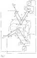
- the vertical triangulation TV is shown in the upper part of FIG. 2 and the horizontal triangulation TH is shown in the lower part.
- a part of a rail head SK in two different positions (translation in the x and z directions) is drawn as the measurement object, with the approximately horizontal contact surface piece FH and the approximately vertical contact surface piece FV.
- the area element FH is considered.
- the illuminating beam BV emanating from the light source QV strikes it at the angle ⁇ against the normal in the middle.
- the light is reflected at the angle ⁇ , forms the beam RV and hits the detector DV at point P1.
- the rail head SK now carries out a translation, which means that FH changes into FH '.
- the extension of the beam BV would no longer hit the surface element FH 'in the center. Therefore, the scanning beam BV has to be shifted parallel to the translation component in the y direction, becomes the beam BV 'and hits the surface element FH' again in the middle.
- the scattered / reflected beam RV 'in turn reaches the detector at the angle ⁇ against the normal at point P2.
- the electrical signal of the detector DV corresponds to a constant of the vertical position of the object. Therefore the difference signal of the detector corresponds to the vertical displacement component.
- the second surface element FV of the measurement object is now considered. It is converted from the SK into the element FV '.
- the light source QH generates a light spot on the center of the surface element FV with a light beam BH at the angle ⁇ against the normal and this light is imaged on the detector DH as a beam RH at the angle ⁇ against the normal at the point P3.
- the surface element FV is converted into the element FV 'by the object shift.
- the beam BH must now be shifted by the translation component in the z direction, becomes beam BH 'and hits the surface element FV' again in the middle.
- the reflected beam RH ' reaches the detector DH at point P4.
- the signal of the detector DH corresponds to a constant of the horizontal position of the object. Therefore, the detector differential signal corresponds to the horizontal displacement component.
- Optical translators are tracking elements that shift a light beam or a corresponding beam path in proportion to an electronic input signal.
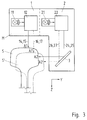
- FIGS. 3 to 5 An embodiment of this invention in the form of a measuring head is shown in FIGS. 3 to 5.
- the measuring head M anchored via a support to two opposite axle bearings contains the vertical measuring head 1 and the horizontal measuring head 2.
- the vertical measuring head 1 consists of the light source 11, the beam translator 12, and the triangulation camera 13 with the detector 18 and the transducer 19.
- the scanning beam 14 is emitted, which strikes the rail S in the surface element A1, is reflected, reaches the beam 15 as the camera 13 onto the detector 18, which outputs the position signal a1 via a converter circuit 19.
- the scanning beam shifts along the line 16, hits the rail S' in A1 ', is converted into the beam 17 by reflection and reaches the detector 18, the signal a2 being generated.
- the horizontal measuring head 2 consists of the light source 21, the beam translator 22, and the triangulation camera 23 with the detector 28 and the transducer 29.
- the scanning beam 24 is emitted, which strikes the rail S after the deflection by the deflection element 3 in the surface element A2 reflects and arrives as a beam 25 in the camera 23 on the detector 28, which outputs the position signal a3 via a converter circuit 29.
- the scanning beam shifts along the line 26, hits the rail S' in A2 ', is converted into the beam 27 by reflection and reaches the detector at point 28 and generates the signal a4.
- control input of the vertical translator 12 receives the position signal of the horizontal output a4 or a3 and vice versa
- the control input of the horizontal translator 22 receives the position signal of the vertical output a2 or a1.
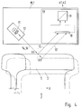
- FIG. 1 An embodiment of an optomechanical beam translator is shown in FIG.
- the beam generated by the light source 11, 21 falls on the central axis of a mirror 30, which coincides with the axis of a galvanometer unit 31. This axis lies in the focal plane of a lens 32.
- the galvanometer input 33 By actuating the galvanometer input 33 with a corresponding position signal, the mirror is rotated into a specific angular position, and the light beam always reaches that parallel to the optical axis Probe surface S.
- the displacement of the beam is proportional to the difference between two control signals 33.
Landscapes
- Engineering & Computer Science (AREA)
- Mechanical Engineering (AREA)
- Physics & Mathematics (AREA)
- General Physics & Mathematics (AREA)
- Length Measuring Devices By Optical Means (AREA)
- Measurement Of Optical Distance (AREA)
Applications Claiming Priority (4)
| Application Number | Priority Date | Filing Date | Title |
|---|---|---|---|
| DE4433185 | 1994-09-17 | ||
| DE4433185 | 1994-09-17 | ||
| DE19531336A DE19531336C2 (de) | 1994-09-17 | 1995-08-25 | Meßvorrichtung zur berührungslosen Erfassung des Vertikal- und Horizontalabstands zwischen Fahrzeug und Schiene |
| DE19531336 | 1995-08-25 |
Publications (3)
| Publication Number | Publication Date |
|---|---|
| EP0708344A2 true EP0708344A2 (fr) | 1996-04-24 |
| EP0708344A3 EP0708344A3 (fr) | 1999-02-03 |
| EP0708344B1 EP0708344B1 (fr) | 2002-01-09 |
Family
ID=25940219
Family Applications (1)
| Application Number | Title | Priority Date | Filing Date |
|---|---|---|---|
| EP95114427A Expired - Lifetime EP0708344B1 (fr) | 1994-09-17 | 1995-09-14 | Système de mesure sans contact pour mesurer la distance verticale et horizontale entre véhicule et rail |
Country Status (2)
| Country | Link |
|---|---|
| EP (1) | EP0708344B1 (fr) |
| AT (1) | ATE211827T1 (fr) |
Cited By (2)
| Publication number | Priority date | Publication date | Assignee | Title |
|---|---|---|---|---|
| EP0908698A3 (fr) * | 1997-09-16 | 2000-10-11 | BETRIEBSFORSCHUNGSINSTITUT VDEh, INSTITUT FÜR ANGEWANDTE FORSCHUNG GmbH | Dispositif de mesure de produits longitudinaux |
| CN107792116A (zh) * | 2017-09-30 | 2018-03-13 | 成都安科泰丰科技有限公司 | 一种便携式接触轨检测装置及检测方法 |
Family Cites Families (2)
| Publication number | Priority date | Publication date | Assignee | Title |
|---|---|---|---|---|
| US3864039A (en) * | 1973-07-12 | 1975-02-04 | Us Transport | Rail gage apparatus |
| FR2700611B1 (fr) * | 1993-01-18 | 1995-03-24 | Matra Sep Imagerie Inf | Procédé et dispositif de contrôle dimensionnel du profil de produits longs. |
-
1995
- 1995-09-14 AT AT95114427T patent/ATE211827T1/de not_active IP Right Cessation
- 1995-09-14 EP EP95114427A patent/EP0708344B1/fr not_active Expired - Lifetime
Cited By (3)
| Publication number | Priority date | Publication date | Assignee | Title |
|---|---|---|---|---|
| EP0908698A3 (fr) * | 1997-09-16 | 2000-10-11 | BETRIEBSFORSCHUNGSINSTITUT VDEh, INSTITUT FÜR ANGEWANDTE FORSCHUNG GmbH | Dispositif de mesure de produits longitudinaux |
| CN107792116A (zh) * | 2017-09-30 | 2018-03-13 | 成都安科泰丰科技有限公司 | 一种便携式接触轨检测装置及检测方法 |
| CN107792116B (zh) * | 2017-09-30 | 2024-05-07 | 成都安科泰丰科技有限公司 | 一种便携式接触轨检测装置及检测方法 |
Also Published As
| Publication number | Publication date |
|---|---|
| EP0708344A3 (fr) | 1999-02-03 |
| EP0708344B1 (fr) | 2002-01-09 |
| ATE211827T1 (de) | 2002-01-15 |
Similar Documents
| Publication | Publication Date | Title |
|---|---|---|
| DE3901185C2 (fr) | ||
| DE69021207T2 (de) | Einrichtung zum gleisgebundenen erfassen des radprofiles von rädern eines zuges. | |
| DE69622940T2 (de) | Installation und Verfahren zum Messen von Rollparametern durch künstliches Sehen bei Eisenbahnfahrzeugrädern | |
| EP0254772B1 (fr) | Méthode de la détermination du diamètre des roues de véhicules sur rail et dispositif pour cela | |
| RU2142892C1 (ru) | Оптоэлектронная система бесконтактного измерения в движении геометрических характеристик железнодорожной колеи. оптоэлектронный датчик бесконтактного измерения положения и износа рельса | |
| EP0212052A2 (fr) | Dispositif pour la mesure des roues d'ensembles de roues intégrées dans le véhicule | |
| WO2009059916A1 (fr) | Système de tête de mesure pour une machine de mesure de coordonnées et procédé de mesure optique de déplacements d'une sonde du système de tête de mesure | |
| WO1998054543A1 (fr) | Mesure de stries et d'ondulations longitudinales au moyen d'un rayon lumineux allonge, sur des rails | |
| EP2769175A1 (fr) | Mesure en temps réel de données de position relative et/ou de cotes géométriques d'un corps en mouvement en utilisant des moyens de mesure optique | |
| DE19510560A1 (de) | Meßvorrichtung zur berührungsfreien Vermessung des Schienenprofils | |
| DE2855877A1 (de) | Verfahren und vorrichtung zur kontinuierlichen und beruehrungslosen messung der form von walz-, zieh- und stranggusserzeugnissen | |
| EP0112399B1 (fr) | Méthode de mesure interférométrique pour des surfaces | |
| DE19531336C2 (de) | Meßvorrichtung zur berührungslosen Erfassung des Vertikal- und Horizontalabstands zwischen Fahrzeug und Schiene | |
| DE102005040772B4 (de) | Optischer Längen- und Geschwindigkeitssensor | |
| EP1982197A1 (fr) | Testeur à pattes pour contrôler des cartes de circuits imprimés non équipées et procédé de contrôle de cartes de circuits imprimés non équipées avec un testeur à pattes | |
| EP0708344B1 (fr) | Système de mesure sans contact pour mesurer la distance verticale et horizontale entre véhicule et rail | |
| EP0346601B1 (fr) | Procédé et dispositif de mesure de la vitesse d'écoulement d'un fluide, en particulier dans un tunnel aérodynamique | |
| GB2178169A (en) | Examination of moving surfaces | |
| DE10256725B3 (de) | Sensor, Vorrichtung und Verfahren zur Geschwindigkeitsmessung | |
| DE3611795A1 (de) | Optisch-elektronische systeme zum beruehrungslosen messen waehrend der fahrt von: querschnittumriss von eisenbahnschienen, querschnittumriss und kenngroessen i, c, q(pfeil abwaerts)r(pfeil abwaerts) der eisenbahnraeder, querschnitt der eisenbahnwaggons, seiten und hoehenabweichungen von eisenbahnschienen | |
| DE19818190B4 (de) | Verfahren und Vorrichtung zur berührungslosen Messung der Wanddicke | |
| WO2023117846A1 (fr) | Procédé et dispositif de mesure d'une voie | |
| DE102006042802A1 (de) | Verfahren und Vorrichtung zum berührungslosen Messen von Bewegungen einer Eisenbahnschiene | |
| DE10114575B4 (de) | Vorrichtung zur Bestimmung der Restdicke wenigstens eines rundlichen Fahrdrahts | |
| EP0356563A1 (fr) | Procédé et appareil de mesure pour déterminer la longueur de fissures et/ou l'élongation de pièces détachées ou d'échantillons |
Legal Events
| Date | Code | Title | Description |
|---|---|---|---|
| PUAI | Public reference made under article 153(3) epc to a published international application that has entered the european phase |
Free format text: ORIGINAL CODE: 0009012 |
|
| AK | Designated contracting states |
Kind code of ref document: A2 Designated state(s): AT BE CH DE DK ES FR GB GR IE IT LI LU MC NL PT SE |
|
| PUAL | Search report despatched |
Free format text: ORIGINAL CODE: 0009013 |
|
| AK | Designated contracting states |
Kind code of ref document: A3 Designated state(s): AT BE CH DE DK ES FR GB GR IE IT LI LU MC NL PT SE |
|
| 17P | Request for examination filed |
Effective date: 19990407 |
|
| 17Q | First examination report despatched |
Effective date: 19991116 |
|
| GRAG | Despatch of communication of intention to grant |
Free format text: ORIGINAL CODE: EPIDOS AGRA |
|
| GRAG | Despatch of communication of intention to grant |
Free format text: ORIGINAL CODE: EPIDOS AGRA |
|
| GRAH | Despatch of communication of intention to grant a patent |
Free format text: ORIGINAL CODE: EPIDOS IGRA |
|
| GRAH | Despatch of communication of intention to grant a patent |
Free format text: ORIGINAL CODE: EPIDOS IGRA |
|
| GRAA | (expected) grant |
Free format text: ORIGINAL CODE: 0009210 |
|
| REG | Reference to a national code |
Ref country code: GB Ref legal event code: IF02 |
|
| AK | Designated contracting states |
Kind code of ref document: B1 Designated state(s): AT BE CH DE DK ES FR GB GR IE IT LI LU MC NL PT SE |
|
| PG25 | Lapsed in a contracting state [announced via postgrant information from national office to epo] |
Ref country code: IT Free format text: LAPSE BECAUSE OF FAILURE TO SUBMIT A TRANSLATION OF THE DESCRIPTION OR TO PAY THE FEE WITHIN THE PRE;WARNING: LAPSES OF ITALIAN PATENTS WITH EFFECTIVE DATE BEFORE 2007 MAY HAVE OCCURRED AT ANY TIME BEFORE 2007. THE CORRECT EFFECTIVE DATE MAY BE DIFFERENT FROM THE ONE RECORDED.SCRIBED TIME-LIMIT Effective date: 20020109 Ref country code: IE Free format text: LAPSE BECAUSE OF FAILURE TO SUBMIT A TRANSLATION OF THE DESCRIPTION OR TO PAY THE FEE WITHIN THE PRESCRIBED TIME-LIMIT Effective date: 20020109 Ref country code: GR Free format text: LAPSE BECAUSE OF FAILURE TO SUBMIT A TRANSLATION OF THE DESCRIPTION OR TO PAY THE FEE WITHIN THE PRESCRIBED TIME-LIMIT Effective date: 20020109 Ref country code: GB Free format text: LAPSE BECAUSE OF FAILURE TO SUBMIT A TRANSLATION OF THE DESCRIPTION OR TO PAY THE FEE WITHIN THE PRESCRIBED TIME-LIMIT Effective date: 20020109 |
|
| REF | Corresponds to: |
Ref document number: 211827 Country of ref document: AT Date of ref document: 20020115 Kind code of ref document: T |
|
| REG | Reference to a national code |
Ref country code: CH Ref legal event code: NV Representative=s name: BUECHEL, KAMINSKI & PARTNER PATENTANWAELTE ESTABLI Ref country code: CH Ref legal event code: EP |
|
| REG | Reference to a national code |
Ref country code: IE Ref legal event code: FG4D Free format text: GERMAN |
|
| REF | Corresponds to: |
Ref document number: 59509988 Country of ref document: DE Date of ref document: 20020214 |
|
| ET | Fr: translation filed | ||
| PG25 | Lapsed in a contracting state [announced via postgrant information from national office to epo] |
Ref country code: SE Free format text: LAPSE BECAUSE OF FAILURE TO SUBMIT A TRANSLATION OF THE DESCRIPTION OR TO PAY THE FEE WITHIN THE PRESCRIBED TIME-LIMIT Effective date: 20020409 Ref country code: PT Free format text: LAPSE BECAUSE OF FAILURE TO SUBMIT A TRANSLATION OF THE DESCRIPTION OR TO PAY THE FEE WITHIN THE PRESCRIBED TIME-LIMIT Effective date: 20020409 Ref country code: DK Free format text: LAPSE BECAUSE OF FAILURE TO SUBMIT A TRANSLATION OF THE DESCRIPTION OR TO PAY THE FEE WITHIN THE PRESCRIBED TIME-LIMIT Effective date: 20020409 |
|
| GBV | Gb: ep patent (uk) treated as always having been void in accordance with gb section 77(7)/1977 [no translation filed] |
Effective date: 20020109 |
|
| PG25 | Lapsed in a contracting state [announced via postgrant information from national office to epo] |
Ref country code: ES Free format text: LAPSE BECAUSE OF FAILURE TO SUBMIT A TRANSLATION OF THE DESCRIPTION OR TO PAY THE FEE WITHIN THE PRESCRIBED TIME-LIMIT Effective date: 20020730 |
|
| REG | Reference to a national code |
Ref country code: IE Ref legal event code: FD4D |
|
| PG25 | Lapsed in a contracting state [announced via postgrant information from national office to epo] |
Ref country code: LU Free format text: LAPSE BECAUSE OF NON-PAYMENT OF DUE FEES Effective date: 20020914 |
|
| PG25 | Lapsed in a contracting state [announced via postgrant information from national office to epo] |
Ref country code: BE Free format text: LAPSE BECAUSE OF NON-PAYMENT OF DUE FEES Effective date: 20020930 |
|
| PLBE | No opposition filed within time limit |
Free format text: ORIGINAL CODE: 0009261 |
|
| STAA | Information on the status of an ep patent application or granted ep patent |
Free format text: STATUS: NO OPPOSITION FILED WITHIN TIME LIMIT |
|
| 26N | No opposition filed | ||
| BERE | Be: lapsed |
Owner name: DEUTSCHE *BAHN A.G. Effective date: 20020930 |
|
| PG25 | Lapsed in a contracting state [announced via postgrant information from national office to epo] |
Ref country code: MC Free format text: LAPSE BECAUSE OF NON-PAYMENT OF DUE FEES Effective date: 20030401 |
|
| PGFP | Annual fee paid to national office [announced via postgrant information from national office to epo] |
Ref country code: NL Payment date: 20040917 Year of fee payment: 10 Ref country code: FR Payment date: 20040917 Year of fee payment: 10 |
|
| PGFP | Annual fee paid to national office [announced via postgrant information from national office to epo] |
Ref country code: AT Payment date: 20040922 Year of fee payment: 10 |
|
| PGFP | Annual fee paid to national office [announced via postgrant information from national office to epo] |
Ref country code: CH Payment date: 20040923 Year of fee payment: 10 |
|
| PG25 | Lapsed in a contracting state [announced via postgrant information from national office to epo] |
Ref country code: AT Free format text: LAPSE BECAUSE OF NON-PAYMENT OF DUE FEES Effective date: 20050914 |
|
| PG25 | Lapsed in a contracting state [announced via postgrant information from national office to epo] |
Ref country code: LI Free format text: LAPSE BECAUSE OF NON-PAYMENT OF DUE FEES Effective date: 20050930 Ref country code: CH Free format text: LAPSE BECAUSE OF NON-PAYMENT OF DUE FEES Effective date: 20050930 |
|
| PGFP | Annual fee paid to national office [announced via postgrant information from national office to epo] |
Ref country code: DE Payment date: 20050930 Year of fee payment: 11 |
|
| PG25 | Lapsed in a contracting state [announced via postgrant information from national office to epo] |
Ref country code: NL Free format text: LAPSE BECAUSE OF NON-PAYMENT OF DUE FEES Effective date: 20060401 |
|
| REG | Reference to a national code |
Ref country code: CH Ref legal event code: PL |
|
| PG25 | Lapsed in a contracting state [announced via postgrant information from national office to epo] |
Ref country code: FR Free format text: LAPSE BECAUSE OF NON-PAYMENT OF DUE FEES Effective date: 20060531 |
|
| NLV4 | Nl: lapsed or anulled due to non-payment of the annual fee |
Effective date: 20060401 |
|
| REG | Reference to a national code |
Ref country code: FR Ref legal event code: ST Effective date: 20060531 |
|
| PG25 | Lapsed in a contracting state [announced via postgrant information from national office to epo] |
Ref country code: DE Free format text: LAPSE BECAUSE OF NON-PAYMENT OF DUE FEES Effective date: 20070403 |