EP0708349A2 - Anordnung zur Justierung der Krümmung eines Umlenkspiegels in einem Rasterscanner - Google Patents
Anordnung zur Justierung der Krümmung eines Umlenkspiegels in einem Rasterscanner Download PDFInfo
- Publication number
- EP0708349A2 EP0708349A2 EP95307447A EP95307447A EP0708349A2 EP 0708349 A2 EP0708349 A2 EP 0708349A2 EP 95307447 A EP95307447 A EP 95307447A EP 95307447 A EP95307447 A EP 95307447A EP 0708349 A2 EP0708349 A2 EP 0708349A2
- Authority
- EP
- European Patent Office
- Prior art keywords
- mirror
- adjusting
- curvature
- raster scanning
- bow
- Prior art date
- Legal status (The legal status is an assumption and is not a legal conclusion. Google has not performed a legal analysis and makes no representation as to the accuracy of the status listed.)
- Granted
Links
- 238000005452 bending Methods 0.000 claims description 26
- 108091008695 photoreceptors Proteins 0.000 claims description 9
- 230000003287 optical effect Effects 0.000 description 15
- 238000000034 method Methods 0.000 description 10
- 239000013256 coordination polymer Substances 0.000 description 7
- 238000007639 printing Methods 0.000 description 4
- 241000226585 Antennaria plantaginifolia Species 0.000 description 2
- 230000009977 dual effect Effects 0.000 description 2
- 238000009825 accumulation Methods 0.000 description 1
- 229910052782 aluminium Inorganic materials 0.000 description 1
- XAGFODPZIPBFFR-UHFFFAOYSA-N aluminium Chemical compound [Al] XAGFODPZIPBFFR-UHFFFAOYSA-N 0.000 description 1
- 239000004568 cement Substances 0.000 description 1
- 239000003086 colorant Substances 0.000 description 1
- 238000006073 displacement reaction Methods 0.000 description 1
- 230000000694 effects Effects 0.000 description 1
- 238000005516 engineering process Methods 0.000 description 1
- 229910052751 metal Inorganic materials 0.000 description 1
- 239000002184 metal Substances 0.000 description 1
Images




Classifications
-
- G—PHYSICS
- G02—OPTICS
- G02B—OPTICAL ELEMENTS, SYSTEMS OR APPARATUS
- G02B5/00—Optical elements other than lenses
- G02B5/08—Mirrors
- G02B5/09—Multifaceted or polygonal mirrors, e.g. polygonal scanning mirrors; Fresnel mirrors
-
- G—PHYSICS
- G02—OPTICS
- G02B—OPTICAL ELEMENTS, SYSTEMS OR APPARATUS
- G02B26/00—Optical devices or arrangements for the control of light using movable or deformable optical elements
- G02B26/08—Optical devices or arrangements for the control of light using movable or deformable optical elements for controlling the direction of light
- G02B26/0816—Optical devices or arrangements for the control of light using movable or deformable optical elements for controlling the direction of light by means of one or more reflecting elements
- G02B26/0825—Optical devices or arrangements for the control of light using movable or deformable optical elements for controlling the direction of light by means of one or more reflecting elements the reflecting element being a flexible sheet or membrane, e.g. for varying the focus
-
- G—PHYSICS
- G02—OPTICS
- G02B—OPTICAL ELEMENTS, SYSTEMS OR APPARATUS
- G02B7/00—Mountings, adjusting means, or light-tight connections, for optical elements
- G02B7/18—Mountings, adjusting means, or light-tight connections, for optical elements for prisms; for mirrors
- G02B7/182—Mountings, adjusting means, or light-tight connections, for optical elements for prisms; for mirrors for mirrors
Definitions
- This invention relates generally to an apparatus and method for adjusting the curvature of a mirror in a raster scanning system. More particularly, this invention relates to adjusting the curvature of a mirror to correct for differential bow in a raster scanning system.
- Flying spot scanners (often referred to as raster output scanners or ROSs) conventionally have a reflective multi-faceted polygon mirror that is rotated about its central axis to repeatedly sweep one or more intensity modulated beams of light across a photosensitive recording medium in a fast scan direction while the recording medium is being advanced in the slow scan direction.
- the beam scans the recording medium based on a raster scanning pattern.
- Digital printing is performed by serially intensity modulating each of the beams in accordance with the binary sample string.
- Printers that sweep several beams simultaneously are referred to as multi-beam printers. Both ROS and multi-beam printer techniques are illustrated in US-A-4,474,422.
- High speed process color or multi-highlight color xerographic image output terminals require multiple independently addressable raster lines to be printed simultaneously at separate exposure stations. This is called multi-station printing.
- Conventional architectures for multi-station process color printers use a plurality of separate ROSs, usually four independent ROSs, one for each system color as illustrated in US-A-4,847,642 and US-A-4,903,067.
- US-A-5,243,359 discloses a ROS system suitable for deflecting multiple laser beams in a multi-station printer.
- Figure 1 of the present application illustrates one embodiment of the multi-station printer 10 of US-A-5,243,359.
- a rotating polygon mirror 12 simultaneously deflects a plurality of clustered, dissimilar wavelength laser beams, having their largest divergent angles parallel to one another.
- the laser beams are subsequently separated by a plurality of optical filters 16, 18 and 20 and are directed onto respective photoreceptors 24, 26, 28 and 30 using mirrors 21 and 22.
- dimensioned spots are obtained on each photoreceptor 24, 26, 28 and 30 by establishing similar optical path lengths for each beam.
- the laser diodes in US-A-5,243,359 are arranged in the slow scan direction (i.e., sagittally offset). Diodes arranged in the slow scan direction must be arranged such that they are packed closely in a direction parallel to the polygon mirror's rotational axis to minimize beam characteristic deviations such as spot size, energy uniformity, bow and linearity. Thus, the laser diodes are kept as closely as possible in the direction parallel to the polygon mirror's rotational axis so that the light beams strike nearly the same portion of the polygon mirror as possible.
- US-A-5,341,158 discloses a ROS system in which the laser beams are tangentially offset (i.e., separated in the fast scan direction) to offset the laser diode spacing constraints of US-A-5,243,359.
- Bow is the curved line described by the scanned laser beam of the ROS as the laser beam moves in the fast scan direction. Bow appears as a displacement of the scan line in the process direction as the line extends in the fast scan direction.
- differential scan line bow rises from the very nature of multi-beam optic systems, where the beams are offset sagittally (i.e., in the slow scan direction). The bow occurs because the magnification of the optical system varies across each sagittal plane as each of the sagittally offset beams propagate through the optical system.
- the differential scan line bow can cause scan lines to move towards each other (barrel distortion) or away from each other (pincushion distortion).
- the light sources are on opposite sides of the optical axis. Therefore, the centers of curvature of the bowed scan lines are also on opposite sides of the optical axis.
- Figures 5A-5C of the present application show the problems of differential scan line bow on the surface of a photoreceptor.
- the ideal scan line 70 is shown as a dashed line.
- the bowed scan line 72 results from the scanning of the laser beam off the optical axis.
- a printed line may be curved rather than straight. Such errors are generally visible to the human eye.
- Figure 5B shows differential bow in a dual spot ROS.
- a dual spot ROS simultaneously images two spots on a single photoreceptor.
- two types of differential bows may occur.
- a second scan line 74 is created that has a radius of curvature different from the radius of curvature of the first scan line 72.
- the centers of curvature of the bowed scanned lines 72 and 74 are on opposite sides of the ideal scan lines 70 and create a pincushion distortion.
- Figure 5C shows the bowed scan lines 76 and 78 having centers of curvature on opposite sides of the ideal scan line 70 to create a barrel distortion.
- EP-A-0,661,573 discloses a multi-beam ROS in which the chief exit rays from the optical system to the photoreceptor are telecentric.
- the multi-beam system becomes both tolerant to pyramidal polygon angular errors and is able to maintain adequately stable, essentially no bow performance over an acceptable depth of focus in the single station xerographic printer.
- multi-station systems are able to print with acceptable levels of misregistration between the various images written on the widely separated xerographic stations.
- FIG 2 of the present application shows a top view of a prior art apparatus for mounting mirrors 22 in a ROS system such as that of Figure 1.
- Each mirror 22 is mounted such that the reflective front surface 23 faces the incoming light beam while the rear surface 25 faces an opposite direction.
- the holding members 34 are securely attached to a mounting board (not shown in Figure 2).
- the holding members 34 may include arms 32 that extend into contact with longitudinal ends of the mirror 22.
- the mirror 22 may be attached to the arms 32 using attaching clips, cement or other types of attaching devices as is well known in the art.
- the mirror 22 in an undeformed mode is unable to correct any differential bow problems.
- a raster scanning system having an image receiving device for receiving a light beam, a scanning device for scanning a light beam across the image receiving device, a mirror located in a path of the light beam between the scanning device and the image receiving device, and an adjusting device for adjusting the curvature of the mirror.
- the invention provides for an optical system that corrects for differential bow problems by adjusting the curvature of a mirror.
- a light beam is scanned onto an image receiving member and the curvature of a mirror is adjusted.
- the adjusted curvature of the mirror substantially eliminates the bow of the light beam on the image receiving member.
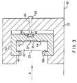
- Figure 3 shows the end view of an adjusting device that adjusts a curvature of the mirror 22.
- the adjusting device includes a mounting device 50 and a bending device 40 positioned at a center location of the mirror 22 between longitudinal ends of the mirror 22.
- the mirror 22 is additionally securely attached at its longitudinal ends to the holding members 34 as shown in Figures 4A and 4B.
- Figures 4A and 4B additionally show the central location of the mounting device 50. Therefore, the mirror 22 is fixed at its longitudinal ends but is capable of bending along its longitudinal axis, the amount of the bending is adjusted by the adjusting device as described below.
- the bending device 40 contacts and holds the mirror 22 preferably using abutments 42, 44, 45 and 45A.
- the rear surface 25 of the mirror 22 has a central longitudinal axis and a central transverse axis which intersect at a center point CP of the mirror 22.
- the abutments 42 and 44 preferably are located in line with the central transverse axis, with each pair equally spaced from the center point CP.
- the bending device 40 includes rear abutments 42 and 44 contacting the rear surface 25 of the mirror 22 on opposite sides of the center point CP of the mirror 22.
- the bending device 40 may additionally include two abutments 45 and 45A contacting a front surface 23 of the mirror 22 on opposite sides of the center point CP at locations near the top and bottom edges of the mirror 22.
- the abutments 42, 44, 45 and 45A are preferably made of soft metal such as aluminum to prevent the mirror 22 from breaking when force is applied by the bending device 40 to adjust the curvature of the mirror 22.
- Other embodiments of the abutments 42, 44, 45 and 45A are also within the scope of this invention.
- the mounting device 50 surrounds the bending device 40. As illustrated in Fig. 4A, the mounting device 50 is preferably secured to a mounting board 90 and allows movement of the bending device 40 relative to the mounting board 90 as will be described below.
- Figure 4A shows a rear view of the mirror 22 and the mounting device 50 with the mounting device 50 located around a center portion of the mirror 22.
- the mounting device 50 extends along the rear surface between the top surface and the front surface of the mirror 22.
- the bending device 40 is not visible from the rear view because the mounting device 50 preferably surrounds the bending device 40.
- the mounting device 50 preferably includes a setting screw 60 that is aligned with the center point CP and extends through the mounting device 50 to the bending device 40.
- the setting screw 60 may include a threaded section 64 received within a threaded hole of the mounting device and an enlarged portion 62 received within a recess 46 of the bending device 40.
- the enlarged portion 62 is a "T-shape" to control movement of the bending device 40 relative to the mounting device 50.
- the mounting device 50 and thus the bending device 40 are located around a center portion of the mirror 22 (i.e., the area near the center point CP).
- the bending device 40 applies a force to the mirror 22 to thereby either "push” or “pull” the center portion of the mirror 22.
- the bending device 40 results in an adjustment of the curvature of the mirror 22 due to bending of the longitudinal axis. That is, the position of the center point CP will move a certain distance out of the plane defined by the longitudinal ends of the mirror, to create a "bow” or "bend” in the mirror 22.
- Typical folding mirrors 22 are capable of easily being adjusted in sag by up to 2 mm, depending on the width and the length of the mirror. However, movements of only a fraction of a millimeter are sufficient to correct for bow problems.
- the bending device 40 and the mounting device 50 preferably adjust the curvature of the last mirror 22 in an optical channel before the light beam impinges on a photoreceptor.
- the present invention can be used with any mirror in the optical system.
- differential bow can be corrected by introducing a compensating bow within any of the mirrors 22 of an optical system using the above-described apparatus and method.
- the compensating bow is introduced, the mirror 22 assumes either a uniform concave form or a uniform convex form.
- computer analysis it has been found that a 14 micron bow in a mirror can eliminate a 9.3 micron bow in the optical system.
- the setting screw 60 is preferably adjusted by a user after first determining the amount of bow in an optical system. This can be done by first allowing a light beam to reflect from the mirror and scan onto a photoreceptor. The bow can then be determined and measured as is well-known in the art. The setting screw 60 is then appropriately adjusted using the above described method and apparatus to correct for the bow. The light beam is then reflected from the mirror and scanned across the photoreceptor with the compensated bow introduced into the mirror. Again, the bow is determined and measured. If necessary, the setting screw 60 is then again adjusted until the bow is substantially eliminated. This process is repeated for each of the four channels of the color printing system shown in Fig 1. Other methods of determining the bow are also within the scope of this invention.
Landscapes
- Physics & Mathematics (AREA)
- General Physics & Mathematics (AREA)
- Optics & Photonics (AREA)
- Mechanical Optical Scanning Systems (AREA)
- Laser Beam Printer (AREA)
- Facsimile Scanning Arrangements (AREA)
Applications Claiming Priority (2)
| Application Number | Priority Date | Filing Date | Title |
|---|---|---|---|
| US08/325,017 US5543829A (en) | 1994-10-19 | 1994-10-19 | Method and apparatus for adjusting the curvature of a folding mirror in a raster scanning system |
| US325017 | 2002-12-19 |
Publications (3)
| Publication Number | Publication Date |
|---|---|
| EP0708349A2 true EP0708349A2 (de) | 1996-04-24 |
| EP0708349A3 EP0708349A3 (de) | 1996-12-11 |
| EP0708349B1 EP0708349B1 (de) | 2001-09-26 |
Family
ID=23266094
Family Applications (1)
| Application Number | Title | Priority Date | Filing Date |
|---|---|---|---|
| EP95307447A Expired - Lifetime EP0708349B1 (de) | 1994-10-19 | 1995-10-19 | Anordnung zur Justierung der Krümmung eines Umlenkspiegels in einem Rasterscanner |
Country Status (4)
| Country | Link |
|---|---|
| US (1) | US5543829A (de) |
| EP (1) | EP0708349B1 (de) |
| JP (1) | JP3745420B2 (de) |
| DE (1) | DE69522885T2 (de) |
Cited By (2)
| Publication number | Priority date | Publication date | Assignee | Title |
|---|---|---|---|---|
| EP0942306A3 (de) * | 1998-03-12 | 2001-10-04 | Sumitomo Electric Industries, Ltd. | Reflektierender Spiegel mit veränderlicher Krümmung |
| GB2460947A (en) * | 2008-06-20 | 2009-12-23 | Boeing Co | Dynamic variable shape optical element assembly and focus correction method |
Families Citing this family (15)
| Publication number | Priority date | Publication date | Assignee | Title |
|---|---|---|---|---|
| US5793408A (en) * | 1994-11-09 | 1998-08-11 | Ricoh Company, Ltd. | Optical scanning apparatus with improved structure for adjusting focus position |
| US5627579A (en) * | 1994-11-29 | 1997-05-06 | Xerox Corporation | Raster scanning optical system and method for adjusting scan line locations on a photoreceptor |
| JP3154938B2 (ja) * | 1996-03-21 | 2001-04-09 | 株式会社東芝 | ビーム光走査装置および画像形成装置 |
| JPH09318895A (ja) * | 1996-05-29 | 1997-12-12 | Konica Corp | 画像形成装置 |
| US5729278A (en) * | 1996-07-01 | 1998-03-17 | Xerox Corporation | Sidewinder raster output scanner |
| NL1006664C2 (nl) * | 1997-07-25 | 1999-01-26 | Oce Tech Bv | Aftastinrichting voor het aftasten van een beelddrager. |
| JP2000039575A (ja) * | 1998-07-16 | 2000-02-08 | Xerox Corp | 走査線弓調整用鏡取付台 |
| US6271869B1 (en) * | 1998-12-15 | 2001-08-07 | Fuji Xerox Co., Ltd. | Multicolor image forming apparatus having adjustable optical members |
| US6496215B2 (en) * | 2000-12-15 | 2002-12-17 | Xerox Corporation | Thermal scan line bow adjustment in an optical scanning system |
| US6490072B2 (en) | 2001-01-12 | 2002-12-03 | Lexmark International, Inc. | Mirror angle adjustment and mounting system for a laser scanner device |
| US6791595B1 (en) * | 2003-02-27 | 2004-09-14 | Xerox Corporation | Bow adjustment in an optical scanning system by adjusting the curvature of a cylindrical mirror |
| JP2004301971A (ja) * | 2003-03-31 | 2004-10-28 | Fuji Photo Optical Co Ltd | 光走査装置 |
| CN100454082C (zh) * | 2004-07-29 | 2009-01-21 | 佳能株式会社 | 具有扫描线弯曲校正机构的光学扫描装置 |
| JP4537285B2 (ja) * | 2004-07-29 | 2010-09-01 | キヤノン株式会社 | 走査線湾曲補正機構を有する光学走査装置 |
| JP5075616B2 (ja) * | 2007-12-27 | 2012-11-21 | 株式会社リコー | 画像形成装置 |
Citations (5)
| Publication number | Priority date | Publication date | Assignee | Title |
|---|---|---|---|---|
| US4474422A (en) | 1979-11-13 | 1984-10-02 | Canon Kabushiki Kaisha | Optical scanning apparatus having an array of light sources |
| US4847642A (en) | 1987-01-30 | 1989-07-11 | Canon Kabushiki Kaisha | Electrophotographic apparatus |
| US4903067A (en) | 1987-04-28 | 1990-02-20 | Canon Kabushiki Kaisha | Multiimage forming apparatus |
| US5243359A (en) | 1991-12-19 | 1993-09-07 | Xerox Corporation | Raster output scanner for a multistation xerographic printing system |
| US5341158A (en) | 1992-09-22 | 1994-08-23 | Xerox Corporation | Raster output scanner for a xerographic printing system having laser diodes arranged in a line parallel to the fast scan direction |
Family Cites Families (6)
| Publication number | Priority date | Publication date | Assignee | Title |
|---|---|---|---|---|
| JPS56140373A (en) * | 1980-04-03 | 1981-11-02 | Fuji Xerox Co Ltd | Mirror aberration correcting device for copying machine |
| DE3036083A1 (de) * | 1980-09-25 | 1982-04-29 | Messerschmitt-Bölkow-Blohm GmbH, 8000 München | Spiegel mit variabler kruemmung |
| US5048904A (en) * | 1990-07-06 | 1991-09-17 | General Scanning, Inc. | Two-mirror scanner with pincushion error correction |
| JPH04264417A (ja) * | 1991-02-19 | 1992-09-21 | Minolta Camera Co Ltd | 走査光学装置 |
| US5233367A (en) * | 1992-09-18 | 1993-08-03 | Xerox Corporation | Multiple beam interlaced scanning system |
| DE4236355C2 (de) * | 1992-10-28 | 2001-11-08 | Zeiss Carl | Adaptiver Membranspiegel |
-
1994
- 1994-10-19 US US08/325,017 patent/US5543829A/en not_active Expired - Lifetime
-
1995
- 1995-10-06 JP JP26042895A patent/JP3745420B2/ja not_active Expired - Fee Related
- 1995-10-19 EP EP95307447A patent/EP0708349B1/de not_active Expired - Lifetime
- 1995-10-19 DE DE69522885T patent/DE69522885T2/de not_active Expired - Lifetime
Patent Citations (5)
| Publication number | Priority date | Publication date | Assignee | Title |
|---|---|---|---|---|
| US4474422A (en) | 1979-11-13 | 1984-10-02 | Canon Kabushiki Kaisha | Optical scanning apparatus having an array of light sources |
| US4847642A (en) | 1987-01-30 | 1989-07-11 | Canon Kabushiki Kaisha | Electrophotographic apparatus |
| US4903067A (en) | 1987-04-28 | 1990-02-20 | Canon Kabushiki Kaisha | Multiimage forming apparatus |
| US5243359A (en) | 1991-12-19 | 1993-09-07 | Xerox Corporation | Raster output scanner for a multistation xerographic printing system |
| US5341158A (en) | 1992-09-22 | 1994-08-23 | Xerox Corporation | Raster output scanner for a xerographic printing system having laser diodes arranged in a line parallel to the fast scan direction |
Cited By (4)
| Publication number | Priority date | Publication date | Assignee | Title |
|---|---|---|---|---|
| EP0942306A3 (de) * | 1998-03-12 | 2001-10-04 | Sumitomo Electric Industries, Ltd. | Reflektierender Spiegel mit veränderlicher Krümmung |
| GB2460947A (en) * | 2008-06-20 | 2009-12-23 | Boeing Co | Dynamic variable shape optical element assembly and focus correction method |
| US7649691B2 (en) | 2008-06-20 | 2010-01-19 | The Boeing Company | Dynamic variable shape optical element |
| GB2460947B (en) * | 2008-06-20 | 2010-09-29 | Boeing Co | Dynamic variable shape optical element |
Also Published As
| Publication number | Publication date |
|---|---|
| US5543829A (en) | 1996-08-06 |
| DE69522885T2 (de) | 2002-03-28 |
| EP0708349B1 (de) | 2001-09-26 |
| JP3745420B2 (ja) | 2006-02-15 |
| EP0708349A3 (de) | 1996-12-11 |
| JPH08122674A (ja) | 1996-05-17 |
| DE69522885D1 (de) | 2001-10-31 |
Similar Documents
| Publication | Publication Date | Title |
|---|---|---|
| EP0708349B1 (de) | Anordnung zur Justierung der Krümmung eines Umlenkspiegels in einem Rasterscanner | |
| US6771296B2 (en) | Optical scanning device and method for providing specific dot offsets at center and ends of scan width | |
| EP1085743B1 (de) | Optisches Abtastgerät mit mehreren Strahlen und Vorrichtung zur Bilderzeugung das dasselbe benutzt | |
| US6587245B2 (en) | Optical scanning device, optical scanning method, and image forming apparatus | |
| EP1111435B1 (de) | Optischer Rasterabtaster mit reduzierter Bauhöhe erreicht durch mehrere Schwankungskorrekturelemente | |
| EP0661573B1 (de) | Optisches Mehrfachstrahlabtastsystem mit telezentrischen Hauptaustrittstrahlen | |
| US5243359A (en) | Raster output scanner for a multistation xerographic printing system | |
| EP0263143B1 (de) | Hochauflösende optische abtastvorrichtung | |
| EP0947335A2 (de) | Laserdrucker unter Verwendung von mehrfachen Lasergruppen mit mehrfachen Wellenlängen | |
| EP0713323B1 (de) | Vielpunkt-Polygonrasterausgabeabtaster mit optimierter Linienabstandsschärfentiefe | |
| EP0672925A1 (de) | Optisches System für Laserprinter | |
| US6621593B1 (en) | Scan line non-linearity correction using an aspheric element in a ROS system | |
| US5617133A (en) | Method and apparatus for adjusting orientation of light beams in a raster scanning system | |
| EP1107038B1 (de) | Optisches Mehrstrahlabtastsystem und Bilderzeugungsvorrichtung unter Verwendung desselben | |
| EP0315428A2 (de) | Mehrstrahliges Polygon-Scannersystem | |
| EP0631166B1 (de) | Rasterscanner mit Abtastbogenfehlerkompensation | |
| EP0843192B1 (de) | Optisches Abtastsystem | |
| EP0549204B1 (de) | Kontrolle der Strahlposition für ein Abtastgerät | |
| US4902084A (en) | Optical scanning system | |
| US5627579A (en) | Raster scanning optical system and method for adjusting scan line locations on a photoreceptor | |
| EP0973055A2 (de) | Einstellung der Krümmung von Abtastzeilen | |
| EP0715197A2 (de) | Anamorphotisches Zoomlinsensystem zur Kontrolle des Abtastlinienabstandes | |
| JPH0980331A (ja) | 複数ビーム走査装置 | |
| JP2001166242A (ja) | 光走査装置およびミラー面調節装置 | |
| JPH01185512A (ja) | 光走査装置 |
Legal Events
| Date | Code | Title | Description |
|---|---|---|---|
| PUAI | Public reference made under article 153(3) epc to a published international application that has entered the european phase |
Free format text: ORIGINAL CODE: 0009012 |
|
| AK | Designated contracting states |
Kind code of ref document: A2 Designated state(s): DE FR GB |
|
| PUAL | Search report despatched |
Free format text: ORIGINAL CODE: 0009013 |
|
| AK | Designated contracting states |
Kind code of ref document: A3 Designated state(s): DE FR GB |
|
| 17P | Request for examination filed |
Effective date: 19970611 |
|
| 17Q | First examination report despatched |
Effective date: 19970806 |
|
| GRAG | Despatch of communication of intention to grant |
Free format text: ORIGINAL CODE: EPIDOS AGRA |
|
| GRAG | Despatch of communication of intention to grant |
Free format text: ORIGINAL CODE: EPIDOS AGRA |
|
| GRAH | Despatch of communication of intention to grant a patent |
Free format text: ORIGINAL CODE: EPIDOS IGRA |
|
| GRAH | Despatch of communication of intention to grant a patent |
Free format text: ORIGINAL CODE: EPIDOS IGRA |
|
| GRAA | (expected) grant |
Free format text: ORIGINAL CODE: 0009210 |
|
| AK | Designated contracting states |
Kind code of ref document: B1 Designated state(s): DE FR GB |
|
| REF | Corresponds to: |
Ref document number: 69522885 Country of ref document: DE Date of ref document: 20011031 |
|
| REG | Reference to a national code |
Ref country code: GB Ref legal event code: IF02 |
|
| ET | Fr: translation filed | ||
| PLBE | No opposition filed within time limit |
Free format text: ORIGINAL CODE: 0009261 |
|
| STAA | Information on the status of an ep patent application or granted ep patent |
Free format text: STATUS: NO OPPOSITION FILED WITHIN TIME LIMIT |
|
| 26N | No opposition filed | ||
| PGFP | Annual fee paid to national office [announced via postgrant information from national office to epo] |
Ref country code: GB Payment date: 20140924 Year of fee payment: 20 |
|
| PGFP | Annual fee paid to national office [announced via postgrant information from national office to epo] |
Ref country code: DE Payment date: 20140924 Year of fee payment: 20 Ref country code: FR Payment date: 20141021 Year of fee payment: 20 |
|
| REG | Reference to a national code |
Ref country code: DE Ref legal event code: R071 Ref document number: 69522885 Country of ref document: DE |
|
| REG | Reference to a national code |
Ref country code: GB Ref legal event code: PE20 Expiry date: 20151018 |
|
| PG25 | Lapsed in a contracting state [announced via postgrant information from national office to epo] |
Ref country code: GB Free format text: LAPSE BECAUSE OF EXPIRATION OF PROTECTION Effective date: 20151018 |