EP0708360B1 - Appareil étanche à la lumière - Google Patents
Appareil étanche à la lumière Download PDFInfo
- Publication number
- EP0708360B1 EP0708360B1 EP95420282A EP95420282A EP0708360B1 EP 0708360 B1 EP0708360 B1 EP 0708360B1 EP 95420282 A EP95420282 A EP 95420282A EP 95420282 A EP95420282 A EP 95420282A EP 0708360 B1 EP0708360 B1 EP 0708360B1
- Authority
- EP
- European Patent Office
- Prior art keywords
- film
- chamber
- camera
- light
- taking lens
- Prior art date
- Legal status (The legal status is an assumption and is not a legal conclusion. Google has not performed a legal analysis and makes no representation as to the accuracy of the status listed.)
- Expired - Lifetime
Links
- 230000000903 blocking effect Effects 0.000 claims description 16
- 238000004519 manufacturing process Methods 0.000 claims description 2
- 238000004804 winding Methods 0.000 description 6
- 238000005286 illumination Methods 0.000 description 4
- 239000003990 capacitor Substances 0.000 description 2
- 239000000839 emulsion Substances 0.000 description 2
- 230000003287 optical effect Effects 0.000 description 2
- 230000015556 catabolic process Effects 0.000 description 1
- 238000006731 degradation reaction Methods 0.000 description 1
- 230000000593 degrading effect Effects 0.000 description 1
- 230000000881 depressing effect Effects 0.000 description 1
- 238000012986 modification Methods 0.000 description 1
- 230000004048 modification Effects 0.000 description 1
- 239000002991 molded plastic Substances 0.000 description 1
- 239000004033 plastic Substances 0.000 description 1
- 230000002028 premature Effects 0.000 description 1
- 238000004064 recycling Methods 0.000 description 1
- 238000006748 scratching Methods 0.000 description 1
- 230000002393 scratching effect Effects 0.000 description 1
Images




Classifications
-
- G—PHYSICS
- G03—PHOTOGRAPHY; CINEMATOGRAPHY; ANALOGOUS TECHNIQUES USING WAVES OTHER THAN OPTICAL WAVES; ELECTROGRAPHY; HOLOGRAPHY
- G03B—APPARATUS OR ARRANGEMENTS FOR TAKING PHOTOGRAPHS OR FOR PROJECTING OR VIEWING THEM; APPARATUS OR ARRANGEMENTS EMPLOYING ANALOGOUS TECHNIQUES USING WAVES OTHER THAN OPTICAL WAVES; ACCESSORIES THEREFOR
- G03B17/00—Details of cameras or camera bodies; Accessories therefor
- G03B17/02—Bodies
Definitions
- the invention relates generally to the field of photography, and in particular to apparatus for preventing stray light from entering the film roll chamber of a camera.
- cameras typically include a film roll chamber for retaining an unexposed roll of film and an adjacent exposure gate which allows light to enter the camera in order to expose the film passing through the exposure gate along a film transport path.
- a light baffle positioned within the exposure gate diffuses the entering light to prevent the premature exposure of the film roll contained in the film roll chamber.
- the light baffle operates most effectively in so called "normal" lighting conditions. However, in extreme lighting instances, such as bright sunlight, it is possible that stray light will not be effectively baffled and will enter the film roll chamber, thereby fogging portions of film roll contained therein.
- US-A-5 311 231 discloses a lens-fitted photographic film unit comprises a main body having a photograph-taking function and a rear cover for shielding the rear of the main body in a light-tight manner.
- the main body has a film supply chamber and a film take-up chamber both of which are provided with respective bottom openings.
- the film supply chamber is provided with a first side edge limiting plate so as partially to shield the bottom opening.
- the rear cover is provided with a cap for closing the bottom opening of the film supply chamber and a second side edge limiting plate.
- a winding shaft is engaged with a film leader of a photographic film, drawn from a photographic film cassette and positioned in a film supply chamber. Similarly, the empty photographic film cassette is positioned in a film take-up chamber.
- an arc-shaped cutout of the first side edge limiting plate faces an arc-shaped cutout of the second side edge limiting plate to form a circular opening through which the winding shaft is inserted and withdrawn.
- the winding shaft is rotated in the opening to wind up the film thereon. After forming a film roll, the winding shaft is pulled out of the film roll through the opening and the cap is closed to seal the unit light-tightly.
- US-A-5 268 713 discloses a lens-fitted photographic film unit is pre-loaded with an unexposed photographic film.
- An exposure station is adapted to exposing the film.
- a film supplying chamber contains a roll of the unexposed film with a first film end wound internally.
- a film take-up chamber is disposed opposite to the film supply chamber, and rotatably contains a spool for holding a second film end. The film as exposed is wound up in the film take-up chamber on the spool, having passed through a chamber entrance to the film take-up chamber.
- An outlet slot is formed behind the film take-up chamber. After completing winding-up of the film, the first film end is exited outward from the outlet slot when the spool is rotated.
- a tongue of a blocking member is movable so that the chamber entrance is left open when the spool rotates in the winding-up direction, and is partly closed when the spool rotates in the unwinding direction.
- the present invention is directed to overcoming one or more of the problems set forth above. Briefly summarized, according to one aspect of the present invention, there is provided a camera as defined in claim 1.
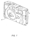
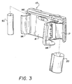
- a preferred embodiment of the present invention is herein described as pertaining to a recyclable single-use camera which is shown in FIGS. 1-9.
- a user exposes the film contained in the camera body and turns the entire film package; that is, the camera and the film contained therein to the photofinisher who unloads the film for development.
- the filmstrip is initially prewound from a film cassette contained in a film cassette chamber of the camera body onto a take-up spool or into a take-up roll chamber of the camera body, so that as exposures are taken, the filmstrip is rewound into a film cartridge which is subsequently removed by a photofinisher.
- the assembled single use camera 10 of the preferred embodiment comprises a main body 12, a front cover 14 which is attached to the front of the main body, and a rear cover 16 that is attached to the rear of the main body.
- Each of the main body 12, the front cover 14 and the rear cover 16 are formed from molded plastic parts.
- the main body 12 includes a pair of formed chambers 17, 18 for retaining a film cassette 20 and a take-up spool 22, respectively.
- the chambers 17, 18 are oppositely disposed relative to an exposure gate 24, which is shown in FIG. 4.
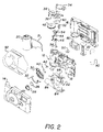
- the body 12 additionally supports a number of camera parts which are attached thereto prior to the attachment of the covers 14, 16 which sandwich the body. These parts include a taking lens 26 which is attached to the front of the body 12 by means of a retainer 28 and a support plate 30, sandwiching the lens therebetween.
- a contact switch 32 is also attached to one side of the support plate 30.
- a plastic viewfinder 34 a shutter mechanism consisting of a keeper plate 38 having a depressable shutter release portion 36 for tripping a shutter blade 40, which is biased by a spring 42 via a high-energy lever 44 which is also biased by a helical spring 46; a film advancing and metering mechanism consisting of a film winding knob 48 which engages the spool (not shown) of a loaded film cassette 20, a sprocket 50 for engaging edge perforations of the film 21 having a spring biased portion extending into a rotatable cam 52 which engages a metering lever 54 biased by a spring 56, the cam 52 having an extending portion for contacting the teeth of a frame counter 60; a light baffle 80 which is mounted into the rear of the body 12 and the exposure gate 24, FIG.
- a flash illumination assembly 82 including a circuit board 84, capacitor 86 and flashhead 88, which is powered by a battery 90.
- the front and rear covers 14, 16 are sandwiched together with the body 12 to form an assembled camera 10.
- a label 92 is subsequently attached to the finished camera 10.
- a breakaway door 94 is provided on the rear cover 14 which allows removal of the film cassette 20 from the film cassette chamber 17.
- the opening of the door 94 breaks the rear cover 14; that is, by destroying the light-tight integrity of the camera 10, but does not expose those parts which are supported by the camera body 12.
- a second breakaway door 96 is also provided on the rear cover 14 to be opened by the photofinisher in order to remove the flash battery 90 from a battery compartment 98, if desired.
- FIG. 4 there is shown a partial top view of the camera 10 having light blocking means according to the prior art.
- the view depicts the camera body 12 having the attached rear cover 16, but does not depict the front cover 14, FIG. 2, which is not shown for ease of discussion.
- Exterior light enters the camera 10 through the taking lens 26 and an openable light portal 100 into an integral exposure chamber 104, the portal 100 being selectively openable by means of tripping the shutter blade 40, FIG. 2, in a manner conventionally known, such as by depressing the shutter release portion 36 of the keeper plate 38, FIG. 2, which uncocks the high energy lever 44, FIG. 2, thereby tripping the shutter blade 40, moving the blade from the portal 100.
- the film 21 passes the exposure gate 24 and the exposure chamber 104 along a film transport path 102, the film extending from the take-up spool 22 which is housed and supported for rotation in the film take-up chamber 18.
- the light entering through the taking lens 26 and portal 100 impinges upon the film 21 as-it passes from the film roll chamber 18 and across the exposure gate 24.
- a majority of the light passes directly through the opening 100 in a direction which is substantially parallel to the optical axis 104 of the lens 26.
- Other portions of the light, such as light ray 108 entering the camera 10 at more oblique angles are either absorbed or diffused by the light baffle 80, FIG. 2, which is disposed within the exposure gate 24.
- Still other portions of light such as light ray 110, enters the opening 100 at a very steep angle, but usually contains less illumination energy than those rays which directly enter the camera, such as along axis 104. Though the light does impinge on the surface of the film 21, this light is usually absorbed.
- the obliquely entering light rays 110 contain considerably more illumination energy. Therefore, as these light rays strike the surface of the film 21, it is possible that a portion of the light rays 110 will be reflected off the surface of the film 21 and into the film roll chamber 18 through the film passage 114 which is defined by the rear cover 16 and the camera body 12, thereby prematurely exposing a portion of the film.
- a thickened portion 112 of the back cover 16 extending into the film passage 114 between the film roll chamber 18 and the exposure chamber 104 fails to adequately shield the film roll chamber from the reflected light ray 110.
- the film 21 is supported for movement along the film transport path 102 by a set of rails 120 which border the upper and lower sides of the exposure gate 24 and extend from the film roll chamber 18 to the film cassette chamber 17, FIG. 5.
- the film transport path 102 extends between the film roll chamber 18 into which the film 21 is prewound from a film cassette 20 positioned within the film cassette chamber 17 and extends toward the film roll chamber 18 for prewinding and away from the film roll chamber for film advancing for exposure.
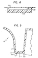
- a light blocking member 116 there is provided between the film roll chamber 18 and the exposure chamber 104, a light blocking member 116 according to the present invention, including a first stepped portion 118 and an adjacent second stepped portion 122.
- the light blocking member 116 is preferably formed as an integral portion of the camera body 12 extending into the film passage 114 and the film transport path 102.
- an ambient light ray 110 entering the exposure chamber 104 impinges onto the emulsion surface of the film 21, but is no longer reflected into the film roll chamber 18, as previously shown in FIG.6, due to the first and second stepped portions 118, 122, respectively, of the light blocking member 116, each of which are sufficiently raised from the surface of a portion 12a of the camera body 12 to shield the film roll chamber 18 from light entering the exposure chamber 104.
- the second stepped portion 122 is raised a greater distance from the body 12 than the first stepped portion 118.
- the enhanced spacing of the second stepped portion 118 of the light blocking member 116 allows the emulsion side of the film 21 to be supported by the second stepped portion 118, rather than having the film surface being supported over its entire width by the light blocking member 116, that is, the first and second stepped portions.
- Supporting the film 21 as described is advantageous in that scratching or other degradation of the film 21 is minimized as the film passes from and to the film cassette chamber 17 to and from the film roll chamber 18 on prewinding and advancing of the film 21 along the film transport path 102.
- the second stepped portion 122 includes a curved outer surface 124 to more easily allow film transport across the light shielding member 116 without sticking or otherwise degrading the film 21.
- FIGS. 1-6 PARTS LIST for FIGS. 1-6
Landscapes
- Physics & Mathematics (AREA)
- General Physics & Mathematics (AREA)
- Camera Bodies And Camera Details Or Accessories (AREA)
- Structure And Mechanism Of Cameras (AREA)
Claims (3)
- Appareil de prise de vues (10) comprenant une chambre de rouleau de film (18) destinée à contenir un rouleau de film non exposé (21), une chambre d'exposition (104) dans laquelle de la lumière ambiante pénètre au travers d'un objectif de prise de vues (26) afin d'être incidente sur le film (21), une partie de corps (12a) séparant ladite chambre de rouleau de film (18) de ladite chambre d'exposition (104), et un moyen d'arrêt de lumière (116) destiné à empêcher la lumière entrant au travers dudit objectif de prise de vues (26) d'entrer dans ladite chambre de rouleau de film (18), ledit moyen d'arrêt de lumière (116) supportant des bords du film (21),
caractérisé en ce que :
ledit moyen d'arrêt de lumière (116) comprend un premier étagement (118) relevé par rapport à ladite partie de corps (12a), ledit premier étagement (118) étant suffisamment relevé pour empêcher la lumière entrant au travers dudit objectif de prise de vues et réfléchie par la surface du film tournée vers l'objectif de prise de vues d'entrer dans ladite chambre de rouleau de film (18) et des second et troisième étagements (122) situés aux extrémités opposées du premier étagement et relevés au-dessus dudit premier étagement (118) afin de supporter les bords du film (21). - Procédé de réalisation d'un appareil de prise de vues à usage unique (10) à partir de pièces d'appareil de prise de vues précédemment utilisées, comprenant les étapes consistant à :
charger un rouleau de film non exposé (21) dans une chambre de cassette de film (15), caractérisé par l'étape consistant à :
pré-enrouler le rouleau de film non exposé à partir de la chambre de cassette de film dans une chambre de rouleau de film (18) en faisant passer le film sur une partie de corps (12a) séparant ladite chambre de rouleau de film d'une chambre d'exposition et sur un premier étagement (118) qui est relevé par rapport à ladite partie de corps et suffisamment relevé pour arrêter la lumière qui peut entrer au travers d'un objectif de prise de vues (26) et être réfléchie par la surface du film tournée vers l'objectif de prise de·vues, d'entrer dans la chambre de rouleau de film et des second et troisième étagements (122) qui sont situés aux extrémités opposées du premier étagement et relevés au-dessus dudit premier étagement afin de supporter les bords du film lorsqu'il est pré-enroulé dans la chambre de rouleau de film. - Appareil de prise de vues selon la revendication 1, dans lequel lesdits second et troisième étagements (122) comprennent une surface extérieure incurvée (124) destinée à permettre au film (21) de se déplacer aisément au travers du moyen d'arrêt de lumière (116).
Applications Claiming Priority (2)
| Application Number | Priority Date | Filing Date | Title |
|---|---|---|---|
| US08/327,251 US5555052A (en) | 1994-10-21 | 1994-10-21 | Light shielding apparatus |
| US327251 | 1994-10-21 |
Publications (2)
| Publication Number | Publication Date |
|---|---|
| EP0708360A1 EP0708360A1 (fr) | 1996-04-24 |
| EP0708360B1 true EP0708360B1 (fr) | 2001-08-01 |
Family
ID=23275762
Family Applications (1)
| Application Number | Title | Priority Date | Filing Date |
|---|---|---|---|
| EP95420282A Expired - Lifetime EP0708360B1 (fr) | 1994-10-21 | 1995-10-13 | Appareil étanche à la lumière |
Country Status (5)
| Country | Link |
|---|---|
| US (2) | US5555052A (fr) |
| EP (1) | EP0708360B1 (fr) |
| JP (1) | JPH08211465A (fr) |
| CN (1) | CN1142058A (fr) |
| DE (1) | DE69521961T2 (fr) |
Families Citing this family (28)
| Publication number | Priority date | Publication date | Assignee | Title |
|---|---|---|---|---|
| US5926662A (en) * | 1993-06-16 | 1999-07-20 | Demaree; Michael S. | Simplified trigger, shutter and film advance system for use in a camera |
| US6349178B1 (en) * | 1994-04-21 | 2002-02-19 | Canon Kabushiki Kaisha | Camera |
| JP3004892B2 (ja) * | 1995-06-21 | 2000-01-31 | 富士写真フイルム株式会社 | レンズ付きフイルムユニット |
| JPH09230479A (ja) * | 1996-02-09 | 1997-09-05 | Konica Corp | 弾性部材付カメラ |
| HUP0204507A2 (en) * | 1996-09-13 | 2003-04-28 | Concord Camera Corp | Film and battery loading method for a single use camera such as a single use aps camera and a camera loaded according to the same |
| US5832311A (en) * | 1996-09-13 | 1998-11-03 | Concord Camera Corp. | Single use camera with battery located in film spool |
| US5862414A (en) * | 1996-09-13 | 1999-01-19 | Concord Camera Corp. | Film and battery loading method for a single use camera such as a single use APS camera and a camera loaded according to the same |
| US6085037A (en) * | 1996-09-13 | 2000-07-04 | Concord Camera Corp. | APS camera structure for film preloading |
| US6081666A (en) * | 1996-09-13 | 2000-06-27 | Concord Camera Corp. | Film and battery loading method for a single use camera such as a single use APS camera and a camera loaded according to the same |
| US5761542A (en) * | 1997-06-03 | 1998-06-02 | Eastman Kodak Company | One-time-use camera with film door which when opened to remove film cartridge breaks anti-backup pawl for film winder wheel |
| US6529687B1 (en) | 1999-03-30 | 2003-03-04 | Concord Camera Corp. | APS camera and method |
| US6283645B1 (en) * | 2000-01-26 | 2001-09-04 | Eastman Kodak Company | Camera with film debris catching comb |
| USD447759S1 (en) | 2000-02-03 | 2001-09-11 | Samsung Techwin Co., Ltd. | Camera |
| JP3557159B2 (ja) * | 2000-08-03 | 2004-08-25 | 三洋電機株式会社 | 機械式絞り装置を具備するビデオカメラ |
| USD442204S1 (en) | 2000-10-18 | 2001-05-15 | Chicony Electronics Co., Ltd. | Camera |
| USD453527S1 (en) | 2000-11-30 | 2002-02-12 | Fuji Photo Film Co., Ltd | Camera |
| US6736555B2 (en) * | 2001-11-28 | 2004-05-18 | Fuji Photo Film Co., Ltd. | Photo film cartridge and camera |
| USD473579S1 (en) | 2002-02-04 | 2003-04-22 | Kabushiki Kaisha Toshiba | Digital still camera |
| USD481405S1 (en) | 2003-03-11 | 2003-10-28 | Casio Keisanki Kabushiki Kaisha | Digital camera |
| TWD103614S1 (zh) | 2003-09-02 | 2005-03-11 | 賓得士股份有限公司 | 數位相機 |
| USD496675S1 (en) | 2003-09-02 | 2004-09-28 | Pentax Corporation | Digital camera |
| USD495727S1 (en) | 2003-10-31 | 2004-09-07 | Hewlett-Packard Development Company, L.P. | Camera |
| WO2005052100A1 (fr) * | 2003-11-26 | 2005-06-09 | Jae Youl Kim | Systeme et procede de fabrication de combustible solide a partir de dechets |
| TWD104587S1 (zh) * | 2003-12-26 | 2005-05-11 | 賓得士股份有限公司 | 數位相機 |
| USD503417S1 (en) | 2004-04-15 | 2005-03-29 | Sony Corporation | Camera |
| USD524838S1 (en) * | 2004-07-06 | 2006-07-11 | Pentax Corporation | Digital camera |
| USD532433S1 (en) * | 2004-12-10 | 2006-11-21 | Canon Kabushiki Kaisha | Digital camera |
| USD528579S1 (en) * | 2005-04-01 | 2006-09-19 | Sony Corporation | Camera |
Family Cites Families (4)
| Publication number | Priority date | Publication date | Assignee | Title |
|---|---|---|---|---|
| JP2527311Y2 (ja) * | 1991-09-03 | 1997-02-26 | 富士写真フイルム株式会社 | レンズ付きフイルムユニット |
| JP2980264B2 (ja) * | 1991-10-03 | 1999-11-22 | 富士写真フイルム株式会社 | レンズ付きフイルムユニット及びその製造方法 |
| JPH06175206A (ja) * | 1992-12-07 | 1994-06-24 | Konica Corp | カメラの遮光構造 |
| JPH06273830A (ja) * | 1993-03-19 | 1994-09-30 | Konica Corp | カメラの遮光構造 |
-
1994
- 1994-10-21 US US08/327,251 patent/US5555052A/en not_active Ceased
-
1995
- 1995-10-02 CN CN95116058.3A patent/CN1142058A/zh active Pending
- 1995-10-13 DE DE69521961T patent/DE69521961T2/de not_active Expired - Fee Related
- 1995-10-13 EP EP95420282A patent/EP0708360B1/fr not_active Expired - Lifetime
- 1995-10-23 JP JP7274085A patent/JPH08211465A/ja active Pending
-
1997
- 1997-02-12 US US08/799,725 patent/USRE35856E/en not_active Expired - Fee Related
Also Published As
| Publication number | Publication date |
|---|---|
| EP0708360A1 (fr) | 1996-04-24 |
| DE69521961T2 (de) | 2002-04-04 |
| CN1142058A (zh) | 1997-02-05 |
| USRE35856E (en) | 1998-07-21 |
| US5555052A (en) | 1996-09-10 |
| JPH08211465A (ja) | 1996-08-20 |
| DE69521961D1 (de) | 2001-09-06 |
Similar Documents
| Publication | Publication Date | Title |
|---|---|---|
| EP0708360B1 (fr) | Appareil étanche à la lumière | |
| US5555063A (en) | Camera with built-in means for closing film cassette and ejecting closed cassette | |
| US5517270A (en) | Camera with built-in means for closing film cassette and tearing open camera to remove closed cassette | |
| US5666561A (en) | One-time-use camera with heat disabling mechanism | |
| US5761542A (en) | One-time-use camera with film door which when opened to remove film cartridge breaks anti-backup pawl for film winder wheel | |
| US5602609A (en) | Camera with film sensor for closing cassette when filmstrip wound completely into cassette | |
| US5555054A (en) | Film loading/unloading design for photographic camera | |
| US5384613A (en) | Single-use camera with weakened area to access film cassette | |
| JPH08171180A (ja) | フィルム一体型カメラの製造方法 | |
| US5412446A (en) | Film assembly apparatus and method for single-use camera employing film securement web | |
| US5881319A (en) | Shutter release button with integral cantilevered support for braking rotatable film sprocket to prevent film movement during exposure | |
| US5974266A (en) | One-time-use camera with film winding thumbwheel removable to unload exposed film roll | |
| US5815738A (en) | Compact one-time-use camera | |
| US5812884A (en) | Closing light lock of film cartridge breaks anti-backup pawl for film winder wheel in one-time-use camera, to prevent unauthorized reuse | |
| US5802401A (en) | Method of remanufacturing one-time-use camera | |
| US5937209A (en) | Camera with film guide rib having film-on-sprocket retention portion | |
| US5978597A (en) | One-time-use camera with break-off protuberance for film ejection | |
| JPH11316406A (ja) | 折り畳んだ場合に使い捨てカメラがコンパクトになるようにフィルムロ―ル室を組み込む跳ね上げ式フラッシュ | |
| US5528326A (en) | Single-use camera with light-blocking film-protective end strip | |
| US5895125A (en) | One-time-use camera can only be used with modified film cartridge, to prevent unauthorized reuse with standard film cartridge | |
| US5708855A (en) | One-time-use camera with built-in flash-every-exposure device incrementally destroyed after each exposure | |
| US6006037A (en) | Compact camera with frame counter and viewfinder integrated to conserve space | |
| JP3668337B2 (ja) | レンズ付きフイルムユニット | |
| JP2583683Y2 (ja) | レンズ付きフイルムユニツト及びフイルムカートリツジ | |
| US6070014A (en) | Anti-backup pawl for manual film winder reinforced when film winder reverse rotated |
Legal Events
| Date | Code | Title | Description |
|---|---|---|---|
| PUAI | Public reference made under article 153(3) epc to a published international application that has entered the european phase |
Free format text: ORIGINAL CODE: 0009012 |
|
| AK | Designated contracting states |
Kind code of ref document: A1 Designated state(s): DE FR GB IT |
|
| 17P | Request for examination filed |
Effective date: 19960919 |
|
| 17Q | First examination report despatched |
Effective date: 19991208 |
|
| GRAG | Despatch of communication of intention to grant |
Free format text: ORIGINAL CODE: EPIDOS AGRA |
|
| GRAG | Despatch of communication of intention to grant |
Free format text: ORIGINAL CODE: EPIDOS AGRA |
|
| GRAH | Despatch of communication of intention to grant a patent |
Free format text: ORIGINAL CODE: EPIDOS IGRA |
|
| GRAH | Despatch of communication of intention to grant a patent |
Free format text: ORIGINAL CODE: EPIDOS IGRA |
|
| GRAA | (expected) grant |
Free format text: ORIGINAL CODE: 0009210 |
|
| ITF | It: translation for a ep patent filed | ||
| AK | Designated contracting states |
Kind code of ref document: B1 Designated state(s): DE FR GB IT |
|
| REF | Corresponds to: |
Ref document number: 69521961 Country of ref document: DE Date of ref document: 20010906 |
|
| ET | Fr: translation filed | ||
| REG | Reference to a national code |
Ref country code: GB Ref legal event code: IF02 |
|
| PLBE | No opposition filed within time limit |
Free format text: ORIGINAL CODE: 0009261 |
|
| STAA | Information on the status of an ep patent application or granted ep patent |
Free format text: STATUS: NO OPPOSITION FILED WITHIN TIME LIMIT |
|
| 26N | No opposition filed | ||
| PGFP | Annual fee paid to national office [announced via postgrant information from national office to epo] |
Ref country code: GB Payment date: 20040915 Year of fee payment: 10 |
|
| PGFP | Annual fee paid to national office [announced via postgrant information from national office to epo] |
Ref country code: FR Payment date: 20041004 Year of fee payment: 10 |
|
| PGFP | Annual fee paid to national office [announced via postgrant information from national office to epo] |
Ref country code: DE Payment date: 20041029 Year of fee payment: 10 |
|
| PG25 | Lapsed in a contracting state [announced via postgrant information from national office to epo] |
Ref country code: IT Free format text: LAPSE BECAUSE OF NON-PAYMENT OF DUE FEES;WARNING: LAPSES OF ITALIAN PATENTS WITH EFFECTIVE DATE BEFORE 2007 MAY HAVE OCCURRED AT ANY TIME BEFORE 2007. THE CORRECT EFFECTIVE DATE MAY BE DIFFERENT FROM THE ONE RECORDED. Effective date: 20051013 Ref country code: GB Free format text: LAPSE BECAUSE OF NON-PAYMENT OF DUE FEES Effective date: 20051013 |
|
| PG25 | Lapsed in a contracting state [announced via postgrant information from national office to epo] |
Ref country code: DE Free format text: LAPSE BECAUSE OF NON-PAYMENT OF DUE FEES Effective date: 20060503 |
|
| GBPC | Gb: european patent ceased through non-payment of renewal fee |
Effective date: 20051013 |
|
| PG25 | Lapsed in a contracting state [announced via postgrant information from national office to epo] |
Ref country code: FR Free format text: LAPSE BECAUSE OF NON-PAYMENT OF DUE FEES Effective date: 20060630 |
|
| REG | Reference to a national code |
Ref country code: FR Ref legal event code: ST Effective date: 20060630 |