EP0708393A1 - Limiteur auto-adaptif pour système automatique d'approche et d'atterrissage - Google Patents
Limiteur auto-adaptif pour système automatique d'approche et d'atterrissage Download PDFInfo
- Publication number
- EP0708393A1 EP0708393A1 EP95116021A EP95116021A EP0708393A1 EP 0708393 A1 EP0708393 A1 EP 0708393A1 EP 95116021 A EP95116021 A EP 95116021A EP 95116021 A EP95116021 A EP 95116021A EP 0708393 A1 EP0708393 A1 EP 0708393A1
- Authority
- EP
- European Patent Office
- Prior art keywords
- vertical speed
- flight path
- nominal
- pitch
- limit
- Prior art date
- Legal status (The legal status is an assumption and is not a legal conclusion. Google has not performed a legal analysis and makes no representation as to the accuracy of the status listed.)
- Granted
Links
- 238000013459 approach Methods 0.000 title claims abstract description 39
- RZVHIXYEVGDQDX-UHFFFAOYSA-N 9,10-anthraquinone Chemical compound C1=CC=C2C(=O)C3=CC=CC=C3C(=O)C2=C1 RZVHIXYEVGDQDX-UHFFFAOYSA-N 0.000 claims description 35
- 238000000034 method Methods 0.000 claims description 10
- 238000012935 Averaging Methods 0.000 claims description 9
- 238000004891 communication Methods 0.000 claims 3
- 230000006870 function Effects 0.000 description 23
- 230000008901 benefit Effects 0.000 description 7
- 238000001514 detection method Methods 0.000 description 7
- 230000008569 process Effects 0.000 description 7
- 238000013461 design Methods 0.000 description 4
- 238000010586 diagram Methods 0.000 description 3
- 238000005259 measurement Methods 0.000 description 3
- 230000008859 change Effects 0.000 description 2
- 230000007423 decrease Effects 0.000 description 2
- 230000001419 dependent effect Effects 0.000 description 2
- 238000012886 linear function Methods 0.000 description 2
- 230000002265 prevention Effects 0.000 description 2
- 230000009471 action Effects 0.000 description 1
- 230000001154 acute effect Effects 0.000 description 1
- 238000004364 calculation method Methods 0.000 description 1
- 238000012937 correction Methods 0.000 description 1
- JXSJBGJIGXNWCI-UHFFFAOYSA-N diethyl 2-[(dimethoxyphosphorothioyl)thio]succinate Chemical compound CCOC(=O)CC(SP(=S)(OC)OC)C(=O)OCC JXSJBGJIGXNWCI-UHFFFAOYSA-N 0.000 description 1
- 238000010348 incorporation Methods 0.000 description 1
- 238000012545 processing Methods 0.000 description 1
- 238000011160 research Methods 0.000 description 1
Images


Classifications
-
- G—PHYSICS
- G05—CONTROLLING; REGULATING
- G05D—SYSTEMS FOR CONTROLLING OR REGULATING NON-ELECTRIC VARIABLES
- G05D1/00—Control of position, course, altitude or attitude of land, water, air or space vehicles, e.g. using automatic pilots
- G05D1/04—Control of altitude or depth
- G05D1/06—Rate of change of altitude or depth
- G05D1/0607—Rate of change of altitude or depth specially adapted for aircraft
- G05D1/0653—Rate of change of altitude or depth specially adapted for aircraft during a phase of take-off or landing
- G05D1/0676—Rate of change of altitude or depth specially adapted for aircraft during a phase of take-off or landing specially adapted for landing
Definitions
- the present invention relates generally to flight control systems for an aircraft and to a method of computing flight path limits for an aircraft according to the preamble of the independent claims and more specifically to fail passive flight control systems for approach and landing.
- Flight control systems control an aircraft's flight profile including takeoff, climb, cruise, descent, approach, and landing. Flight control systems often comprise several different components which influence the control of an aircraft.
- a basic flight control system includes an autopilot and a flight director. More sophisticated systems include flight management systems, performance management systems, wind shear detection systems, and the like.
- the flight director generates pitch and roll commands which are communicated to the autopilot.
- the autopilot implements control laws pertaining to the pitch, roll, and yaw of the aircraft and directly controls actuators which in turn move the control surfaces of the aircraft.
- a problem with flight control systems is that a failure can lead to catastrophic results. This problem is particularly acute during approach and landing where the aircraft is in close proximity to the ground giving a pilot little time to react to a flight system failure.
- Hardover failures are failures in the hardware or software of a flight control system that command abrupt full scale movement of an aircraft control surface.
- Slowover failures are failures in the hardware or software of the flight control system which cause a slow or gradual deviation from the desired flight command.
- FIG. 1 One approach to detection and prevention of failures is illustrated in figure 1 where flight director 10 communicates a pitch command 11 to autopilot 12 which controls the aircraft servos or actuators 14 which in turn control the aircraft flight surfaces 15.
- autopilot fault detection 13 is provided in the flight director 10. In these systems, autopilot fault detection 13 compares feedback 16 from actuators 14 to desired flight director commands 11 thus verifying proper operation of autopilot 12.
- This type of fault detection and similar systems only detect failures in the autopilot 12 and do not detect failures in the flight director 10. Slowover failures can result from this failure to detect flight director failures.
- Multi-channel flight control systems use multiple flight control channels each of which communicate commands to a comparator which detects differences between the channels.
- a first flight director 20 computes a first pitch command 21 to a first autopilot 22 which in turn transmits a first servo command 23 to comparator 24.
- a second flight director 25 communicates a second pitch command 26 to a second autopilot 27 which in turn communicates a second servo command 28 to comparator 24. If comparator 24 detects a significant difference between the commands the comparator attempts to determine which signal or command is correct and disregards the erroneous signal. However, if both channels are identical, a generic failure can occur in both channels simultaneously resulting in both commands being erroneous.
- multi-channel multi-version flight control systems are predominantly used. These systems use multiple dissimilar channels which differ in hardware design, software design, or both hardware and software design from the other channels. This design eliminates the possibility of generic failures in the hardware or the software.
- Multi-channel multi-version flight control systems are reliable, however, they are expensive. Multiple versions of software must be developed, multiple versions of hardware must be developed, and both systems must produce nearly identical commands at nearly the same time (known as cross equalization) for the comparator to operate correctly.
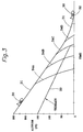
- Figure 3 illustrates the affect of a slowover failure during approach.
- aircraft 30 follows the ILS approach flight path 31 to runway 32.
- Aircraft 30 must remain at a safe altitude above the terrain 33.
- a slowover failure of the pitch or vertical speed of the aircraft can cause aircraft 30 to gradually descend below a safe altitude on approach as illustrated by alternate flight paths 34A, 34B, 34C, and 34D.
- flight control systems would be greatly enhanced by the ability to detect slowover failures especially during approach and landing of an aircraft.
- Current single channel flight control systems do not adequately address the problem of slowover failures.
- multi-channel and multi-version flight control systems would be enhanced if each channel of the multi-channel system was able to detect slowover failures.
- the invention creates a self-adaptive limiter for use in aircraft control systems during approach and landing.
- the limiter limits the pitch command communicated from a flight director to an autopilot during approach and landing.
- the limiter computes a pitch limit value in a unique way which is simple, automatically adapts to changes in the ground speed of the aircraft, wind, and ILS beam angles; and is easily adapted to other aircraft.
- the limiter To compute the pitch limit the limiter first computes an estimated flight path angle as a function of the vertical speed and ground speed of the aircraft. An average (or nominal) flight path angle is continuously computed from the estimated flight path angle during glideslope tracking phase of the approach until, at a predetermined lock altitude above ground, the nominal flight path angle is latched and remains constant for the remainder of the approach and landing.
- a nominal vertical speed is continually computed as a function of the latched nominal flight path angle and ground speed. From nominal vertical speed and radio altitude a vertical speed limit is also continuously computed. The vertical speed limit is computed to ensure that if the aircraft does not exceed the vertical speed limit then it will not descend below the certification terrain clearance requirements. The vertical speed limit is converted into a corresponding pitch limit value allowing easy comparison and limiting of pitch commands communicated to the autopilot.
- the limiter is self-adaptive since the pitch limit computed by the limiter adapts to changes in the ground speed of the aircraft, winds, and ILS beam angles.
- Figure 4 illustrates the affect of the invention during a slowover failure.
- Aircraft 30 normally follows ILS glideslope 31 to a safe landing on runway 32.
- the limiter limits the pitch commands so that aircraft 30 does not descend below a safe altitude thus preventing catastrophic results.
- An object of the invention is to prevent unreasonable flight director commanded maneuvers on approach and landing at low altitude.
- Another object of the invention is to provide fail-passive operation during approach and landing at low altitude.
- a feature of the invention is the self-adaptive algorithm used to compute the pitch limit.
- An advantage of the invention is dissimilar architecture between the flight director and the limiter thus preventing generic failures.
- Another advantage is the simple design which is easily implemented and requires minimal execution time.
- Yet another advantage is that no cross-channel equalization is required.
- Yet another advantage is the protection provided against ILS glideslope signal failures.
- the invention increases the safety of flight control systems by detecting and correcting slowover failures during approach and landing.
- the invention is simple to implement, can be implemented in almost any flight control system, is easily ported to different aircraft, and also provides protection against ILS glideslope system failures.
- Figure 1 is a block diagram of a single channel flight control system.
- Figure 2 shows a multi-channel flight control system.
- Figure 3 illustrates the affect of a slowover failure on the flight path of an aircraft on approach.
- Figure 4 illustrates the affect of the invention on the flight path during a slowover failure on approach.
- Figure 5 illustrates the invention embodied as a single channel flight control system.
- FIG. 6 is a block diagram of the invention.
- FIG. 7 illustrates the vertical speed limit function in detail.
- FIG 8 is a flowchart of the invention.
- Figure 5 illustrates the preferred embodiment of the invention as a pitch limiter in a single channel flight control system.
- Flight director 10 generates a pitch command 11 which is communicated to autopilot 50.
- Pitch limiter 51 is preferably part of autopilot 50.
- Pitch command 11 is processed by pitch limiter 51 before it is processed by the control law portion 52 of autopilot 50.
- the invention's simple design allows it to be easily incorporated into autopilot 50.
- flight director 10 and autopilot 50 are separate boxes which communicate via cable, wires, buses, or the like. However, in some systems the flight director and the autopilot may be incorporated into a single box and may even share hardware resources such as memory and processors.
- the preferred embodiment has separate processors and memory for the flight director and the autopilot.
- the limiter is incorporated into the front end of the autopilot such that pitch commands to the autopilot are checked, and limited if necessary, prior to processing by the remainder of the autopilot.
- This embodiment provides safety related advantages since the limiter algorithm is dissimilar from the flight director algorithms and is implemented on separate hardware thus reducing the risk of generic failures.
- pitch limiter 51 is activated to check pitch commands 11 communicated to autopilot 50 to verify that pitch commands 11 will not cause the aircraft to descend below a safe altitude.
- Pitch limiter 51 communicates the limited pitch command 53 to the control law portion 52 of autopilot 50 which transmits commands to the appropriate aircraft actuators which move the control surfaces thus implementing the pitch command.
- the invention can be implemented in several alternate embodiments including, but not limited to, placing the pitch limiter in the flight director 10 or in a separate box. If the limiter is part of the flight director, however, it does not have the advantage of dissimilar hardware platforms between the pitch limiter 51 and flight director 10 and is therefore more susceptible to generic failures.
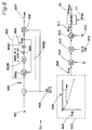
- Figure 6 is a block diagram of the preferred embodiment of the invention.
- Pitch limiter 51 computes estimated flight path angle 600 from the vertical speed 601 and ground speed 602 of the aircraft.
- Vertical speed 601 of the aircraft is divided by ground speed 602 of the aircraft over 57.3 which is a conversion factor representing the number of degrees per radian.
- Vertical speed 601 is obtained from other aircraft systems such as the air data computer system, the inertial reference system, the attitude heading reference system, or the like.
- ground speed 602 is obtained from other systems in the aircraft.
- true air speed or other value representative of the horizontal speed of the aircraft may also be used.
- the term "horizontal speed" is used to represent either ground speed, true air speed, or similar velocity measurement.
- the term "57.3" is used to compute a small angle approximation for the tangent and arc tangent trigonometric functions and is used to reduce execution time.
- Estimated flight path angle 600 is input to averaging filter 603.
- Averaging filter 603 averages estimated flight path angle 600 over time to produce a nominal flight path angle 604 which is representative of the actual flight path angle of the aircraft.
- the preferred embodiment uses an averaging filter comprising a difference device 603A, a time constant 603B, an integrator 603C, and a feedback loop 603D.
- Feedback loop 603D communicates nominal flight path angle 604 to difference device 603A which calculates the difference between the nominal flight path angle 604 and the estimated flight path angle 600 producing a difference flight path angle which is input to time constant 603B which limits the amount of change per unit time.
- the output of time constant 603B is communicated to the input of integrator 603C through switch 605.
- Switch 605 represents the latching of the nominal flight path angle 604 when the aircraft descends below the lock altitude which is 225 feet above ground level in the preferred embodiment. Those skilled in the art recognize that the lock altitude may be changed as desired for an alternate embodiment.
- Integrator 603C sums the values communicated to its inputs and generates nominal flight path angle 604.
- averaging filter 603 is disabled by switch 605 and nominal flight path angle 604 is latched and remains constant for the remainder of the approach and landing.
- averaging filter 603 which are known in the art and will accomplish substantially the same result.
- switch 605 which latches the nominal flight path angle value, may be implemented in many equivalent ways, particularly if the invention is implemented in software.
- Nominal flight path angle 604 is next communicated to multiplier 606.
- Multiplier 606 multiplies nominal flight path angle 604 times horizontal speed 602 over 57.3 degrees per radian thus producing nominal vertical speed 607. As discussed above, 57.3 is the small angle approximation for the tangent and arc tangent functions.
- Nominal vertical speed 607 is self-adaptive since it varies according to changes in horizontal speed 602. If the horizontal speed changes during approach and landing, nominal vertical speed 607 is automatically changed to adapt to the change.
- Vertical speed limit 608 is calculated as a function of nominal vertical speed 607 and altitude 609 of the aircraft above the ground.
- the vertical speed limit function is illustrated by the function displayed inside of box 610. Calculation of vertical speed limit 608 is described in detail below.
- Radio altitude is the preferred measurement for altitude 609, however, those skilled in the art understand that other altitude measurements may be used.
- Vertical speed limit 608 represents the maximum safe descent rate for the aircraft on approach and landing.
- the vertical speed limit function is self-adaptive since it is dependent on nominal vertical speed 607 which is also self-adaptive. Accordingly, as the aircraft horizontal speed changes during approach and landing so does vertical speed limit 608.
- vertical speed limit 608 can readily be adapted for use in many flight control systems to limit the vertical speed of an aircraft on approach and landing. In the preferred embodiment, however, vertical speed limit 608 is converted to an equivalent pitch limit which allows easy comparison and limiting of pitch commands between a flight director and an autopilot.
- Pitch limit 611 is computed from vertical speed limit 608 as follows. First, the difference between vertical speed limit 608 and actual vertical speed 601 of the aircraft is computed by second difference device 612. The output of second difference device 612 is input into second multiplier device 613 which produces a difference flight path angle by multiplying the output of difference device 612 by 57.3 degrees per radian over horizontal speed 602. As discussed above, 57.3 is used to compute the small angle approximation for the tangent and arc tangent functions.
- pitch limit 611 is easily compared to pitch commands 11 received by an autopilot 50. It should be noted that pitch limit 611 is self-adaptive and changes during approach and landing as the wind and horizontal speed 602 of the aircraft changes.
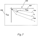
- Figure 7 illustrates the vertical speed limit function
- the vertical speed limit function 71 approaches zero as altitude 609 goes to zero according to a predetermined flare function thus causing the aircraft to flare as it approaches the ground. In the preferred embodiment this is done with a linear function. However, it is envisioned that future embodiments will utilize a curved function which more closely approximates the flare maneuver of an aircraft.
- vertical speed limit function may utilize curved safety margin functions which may extend below 50 feet.
- the vertical speed limit function 71 changes dynamically with changes in the aircraft's horizontal speed and wind. For example, as the horizontal speed of the aircraft decreases nominal vertical speed 607 also decreases causing the vertical speed limit function 71 to move toward dashed line 70A. Conversely, as the horizontal speed of the aircraft increases nominal vertical speed 607 increases causing the vertical speed limit function 71 to move toward dashed line 70B.
- FIG 8 is a flowchart of a possible embodiment of the invention.
- the flowchart illustrates the major steps during one iteration. In most embodiments, these steps are executed multiple times a second during approach and landing. Those skilled in the art understand that many alternate, yet equivalent, embodiments of this flowchart are possible.
- the flowchart begins at start 80 and proceeds to decision box 81 where altitude is compared to 225 feet (lock altitude). If altitude is above 225 feet then the process proceeds to compute estimated flight path angle 82 and compute nominal flight path angle 83. The process then continues to compute nominal vertical speed 84.
- the process proceeds directly to compute the nominal vertical speed 84 and skips computation of estimated flight path angle 82 and nominal flight path angle 83 since these values are latched below 225 feet.
- the process continues on to compute the vertical speed limit 85 and compute the pitch limit 86.
- the process then proceeds to the second decision box 87 where the pitch command from the flight director is compared to the pitch limit computed in step 86 above. If the pitch command is less than the pitch limit (i.e. an excessive pitch down attitude is commanded) then the process proceeds to set the pitch command equal to the pitch limit, step 88, and then proceeds to end 89. If the pitch command is not less than the pitch limit the pitch command is not altered and the process proceeds to end 89.
- Alternate embodiments of the invention envisioned include, but are not limited to, incorporation of the invention into multi-channel multi-version flight control systems, flight directors, flight management systems, electronic flight instrument systems(EFIS), and the like.
- EFIS electronic flight instrument systems
- the present invention represents a new and useful device for detection and correction of slowover failures during approach and landing.
- the invention is simple, reliable, eliminates the need for cross channel equalization between multiple channels, and provides protection against ILS glideslope signal failures.
Landscapes
- Engineering & Computer Science (AREA)
- Aviation & Aerospace Engineering (AREA)
- Radar, Positioning & Navigation (AREA)
- Remote Sensing (AREA)
- Physics & Mathematics (AREA)
- General Physics & Mathematics (AREA)
- Automation & Control Theory (AREA)
- Traffic Control Systems (AREA)
- Control Of Position, Course, Altitude, Or Attitude Of Moving Bodies (AREA)
Applications Claiming Priority (2)
| Application Number | Priority Date | Filing Date | Title |
|---|---|---|---|
| US08/325,836 US5826834A (en) | 1994-10-19 | 1994-10-19 | Self adaptive limiter for automatic control of approach and landing |
| US325836 | 1994-10-19 |
Publications (2)
| Publication Number | Publication Date |
|---|---|
| EP0708393A1 true EP0708393A1 (fr) | 1996-04-24 |
| EP0708393B1 EP0708393B1 (fr) | 2001-04-11 |
Family
ID=23269652
Family Applications (1)
| Application Number | Title | Priority Date | Filing Date |
|---|---|---|---|
| EP95116021A Expired - Lifetime EP0708393B1 (fr) | 1994-10-19 | 1995-10-11 | Limiteur auto-adaptif pour système automatique d'approche et d'atterrissage |
Country Status (3)
| Country | Link |
|---|---|
| US (1) | US5826834A (fr) |
| EP (1) | EP0708393B1 (fr) |
| DE (1) | DE69520641T2 (fr) |
Cited By (6)
| Publication number | Priority date | Publication date | Assignee | Title |
|---|---|---|---|---|
| US6492934B1 (en) * | 2001-08-06 | 2002-12-10 | Rockwell Collins | Method of deriving ground speed for descending aircraft |
| FR2920231A1 (fr) * | 2007-08-20 | 2009-02-27 | Airbus France Sas | Procede et dispositif de protection automatique d'un aeronef contre un atterissage dur |
| EP2104886A4 (fr) * | 2006-12-11 | 2013-07-24 | Embraer Aeronautica Sa | Système de commande de vol |
| CN104035335A (zh) * | 2014-05-27 | 2014-09-10 | 北京航空航天大学 | 基于高精度纵、横程解析预测方法的平稳滑翔再入制导律 |
| CN104965515A (zh) * | 2015-06-12 | 2015-10-07 | 南京航空航天大学 | 一种基于自适应控制的螺旋桨无人靶机的姿态控制方法 |
| FR3023368A1 (fr) * | 2014-07-04 | 2016-01-08 | Airbus Operations Sas | Procede et dispositif d'aide a l'atterrissage d'un aeronef. |
Families Citing this family (11)
| Publication number | Priority date | Publication date | Assignee | Title |
|---|---|---|---|---|
| FR2754364B1 (fr) * | 1996-10-03 | 1998-11-27 | Aerospatiale | Procede et dispositif de guidage vertical d'un aeronef |
| US6456940B1 (en) | 1998-11-20 | 2002-09-24 | Amsaad, Inc. | Minimum safe altitude system and method |
| US6422517B1 (en) * | 1999-12-02 | 2002-07-23 | Boeing Company | Aircraft tailstrike avoidance system |
| FR2852683B1 (fr) * | 2003-03-19 | 2005-05-20 | Airbus France | Procede et dispositif d'aide au pilotage d'un aeronef lors d'une approche de non precision pendant une phase d'atterrissage. |
| US7693620B2 (en) * | 2005-05-31 | 2010-04-06 | The Boeing Company | Approach guidance system and method for airborne mobile platform |
| FR2897154B1 (fr) * | 2006-02-08 | 2008-03-07 | Airbus France Sas | Dispositif pour construire et securiser une trajectoire de vol a basse altitude destinee a etre suivie par un aeronef. |
| US8508387B2 (en) | 2007-05-24 | 2013-08-13 | Aviation Communication & Surveillance Systems Llc | Systems and methods for aircraft windshear detection |
| SG192204A1 (en) | 2011-01-30 | 2013-09-30 | Elbit Systems Ltd | Dynamic limitation of monoblock flight control surfaces inclinations during stall susceptibility conditions |
| ES2694427T3 (es) * | 2013-06-06 | 2018-12-20 | The Boeing Company | Método y sistema de control de velocidad de la aeronave |
| FR3032551B1 (fr) | 2015-02-09 | 2020-11-06 | Airbus Operations Sas | Systeme et procede de pilotage d'un aeronef. |
| CN113961011B (zh) * | 2021-09-16 | 2024-03-19 | 中国航空工业集团公司西安飞机设计研究所 | 一种航迹倾角保持控制方法 |
Citations (7)
| Publication number | Priority date | Publication date | Assignee | Title |
|---|---|---|---|---|
| EP0078688A1 (fr) * | 1981-11-03 | 1983-05-11 | Sperry Corporation | Appareil de commande de vitesse d'avion |
| EP0084447A2 (fr) * | 1982-01-18 | 1983-07-27 | Honeywell Inc. | Appareil de commande de vol automatique d'un avion |
| EP0109315A1 (fr) * | 1982-08-18 | 1984-05-23 | Societe Francaise D'equipements Pour La Navigation Aerienne (S.F.E.N.A.) | Procédé et dispositif de pilotage d'un aérodyne dans le plan vertical |
| US4485446A (en) * | 1981-09-08 | 1984-11-27 | The Boeing Company | Aircraft lift control system with acceleration and attitude limiting |
| EP0253614A2 (fr) * | 1986-07-16 | 1988-01-20 | Honeywell Inc. | Système de commande de la trajectoire verticale et de la vitesse par rapport à l'air d'un avion |
| GB2240957A (en) * | 1990-02-17 | 1991-08-21 | Smiths Industries Plc | Aircraft performance monitoring during landing flare stage |
| EP0530924A2 (fr) * | 1991-09-03 | 1993-03-10 | The Boeing Company | Système de contrôle de l'arrondi pour un avion utilisant un limiteur d'enveloppe |
Family Cites Families (11)
| Publication number | Priority date | Publication date | Assignee | Title |
|---|---|---|---|---|
| FR1517949A (fr) * | 1967-02-08 | 1968-03-22 | Csf | Calculateur de pente vraie |
| US3698669A (en) * | 1970-03-16 | 1972-10-17 | Rita Ann Miller | Method and apparatus for controlling the flight path angle of aircraft |
| US3887148A (en) * | 1973-12-19 | 1975-06-03 | Sperry Rand Corp | Aircraft glide slope coupler and landing system |
| US3930610A (en) * | 1974-06-03 | 1976-01-06 | Hache Jean Guy | Method and apparatus for obtaining accurately the angle of attack of an aircraft |
| US4043526A (en) * | 1976-02-23 | 1977-08-23 | The United States Of America As Represented By The Secretary Of The Navy | Autopilot hardover failure protection system |
| DE2807902C2 (de) * | 1978-02-24 | 1980-04-30 | Messerschmitt-Boelkow-Blohm Gmbh, 8000 Muenchen | Steuereinrichtung mit aktiver Kraft rückführung |
| US4609987A (en) * | 1983-03-09 | 1986-09-02 | Safe Flight Instrument Corporation | Aircraft guidance system for take off or go-around during severe wind shear |
| US4714929A (en) * | 1986-09-04 | 1987-12-22 | Davidson Eldon F | Digital averaging filter particularly suited for use with air navigation receivers |
| US4947165A (en) * | 1987-09-30 | 1990-08-07 | Zweifel Terry L | Windshear detection for aircraft using temperature lapse rate |
| US5361065A (en) * | 1990-05-11 | 1994-11-01 | Honeywell Inc. | Windshear guidance system |
| US5224664A (en) * | 1991-07-22 | 1993-07-06 | United Technologies Corporation | Adaptive control system input limiting |
-
1994
- 1994-10-19 US US08/325,836 patent/US5826834A/en not_active Expired - Fee Related
-
1995
- 1995-10-11 DE DE69520641T patent/DE69520641T2/de not_active Expired - Fee Related
- 1995-10-11 EP EP95116021A patent/EP0708393B1/fr not_active Expired - Lifetime
Patent Citations (7)
| Publication number | Priority date | Publication date | Assignee | Title |
|---|---|---|---|---|
| US4485446A (en) * | 1981-09-08 | 1984-11-27 | The Boeing Company | Aircraft lift control system with acceleration and attitude limiting |
| EP0078688A1 (fr) * | 1981-11-03 | 1983-05-11 | Sperry Corporation | Appareil de commande de vitesse d'avion |
| EP0084447A2 (fr) * | 1982-01-18 | 1983-07-27 | Honeywell Inc. | Appareil de commande de vol automatique d'un avion |
| EP0109315A1 (fr) * | 1982-08-18 | 1984-05-23 | Societe Francaise D'equipements Pour La Navigation Aerienne (S.F.E.N.A.) | Procédé et dispositif de pilotage d'un aérodyne dans le plan vertical |
| EP0253614A2 (fr) * | 1986-07-16 | 1988-01-20 | Honeywell Inc. | Système de commande de la trajectoire verticale et de la vitesse par rapport à l'air d'un avion |
| GB2240957A (en) * | 1990-02-17 | 1991-08-21 | Smiths Industries Plc | Aircraft performance monitoring during landing flare stage |
| EP0530924A2 (fr) * | 1991-09-03 | 1993-03-10 | The Boeing Company | Système de contrôle de l'arrondi pour un avion utilisant un limiteur d'enveloppe |
Cited By (11)
| Publication number | Priority date | Publication date | Assignee | Title |
|---|---|---|---|---|
| US6492934B1 (en) * | 2001-08-06 | 2002-12-10 | Rockwell Collins | Method of deriving ground speed for descending aircraft |
| EP2104886A4 (fr) * | 2006-12-11 | 2013-07-24 | Embraer Aeronautica Sa | Système de commande de vol |
| FR2920231A1 (fr) * | 2007-08-20 | 2009-02-27 | Airbus France Sas | Procede et dispositif de protection automatique d'un aeronef contre un atterissage dur |
| US8240615B2 (en) | 2007-08-20 | 2012-08-14 | Airbus Operations Sas | Method and device for automatically protecting an aircraft against a hard landing |
| CN104035335A (zh) * | 2014-05-27 | 2014-09-10 | 北京航空航天大学 | 基于高精度纵、横程解析预测方法的平稳滑翔再入制导律 |
| CN104035335B (zh) * | 2014-05-27 | 2017-01-04 | 北京航空航天大学 | 基于高精度纵、横程解析预测方法的平稳滑翔再入制导方法 |
| FR3023368A1 (fr) * | 2014-07-04 | 2016-01-08 | Airbus Operations Sas | Procede et dispositif d'aide a l'atterrissage d'un aeronef. |
| CN105235911A (zh) * | 2014-07-04 | 2016-01-13 | 空中客车运营简化股份公司 | 用于飞行器的着陆辅助方法和着陆辅助设备 |
| US9776734B2 (en) | 2014-07-04 | 2017-10-03 | Airbus Operations (S.A.S.) | Landing aid method and device for an aircraft |
| CN105235911B (zh) * | 2014-07-04 | 2018-08-10 | 空中客车运营简化股份公司 | 用于飞行器的着陆辅助方法和着陆辅助设备 |
| CN104965515A (zh) * | 2015-06-12 | 2015-10-07 | 南京航空航天大学 | 一种基于自适应控制的螺旋桨无人靶机的姿态控制方法 |
Also Published As
| Publication number | Publication date |
|---|---|
| DE69520641T2 (de) | 2001-09-13 |
| EP0708393B1 (fr) | 2001-04-11 |
| DE69520641D1 (de) | 2001-05-17 |
| US5826834A (en) | 1998-10-27 |
Similar Documents
| Publication | Publication Date | Title |
|---|---|---|
| US5826834A (en) | Self adaptive limiter for automatic control of approach and landing | |
| US5901927A (en) | Ground strike protection function for aircraft autopilot | |
| US5746392A (en) | Autopilot/flight director underspeed protection system | |
| EP2188144B1 (fr) | Systèmes de protection contre le décrochage, le tremblement et l'assiette élevée | |
| US4801110A (en) | Approach to hover control system for helicopters | |
| KR100232332B1 (ko) | 헬리콥터 고속 회전 조정시스템 | |
| EP0743245B1 (fr) | Système d'obtention d'un signal en air/par terre pour systèmes de contrôle de vol pour aéronefs | |
| US4357661A (en) | Aircraft landing control system | |
| EP0253614A2 (fr) | Système de commande de la trajectoire verticale et de la vitesse par rapport à l'air d'un avion | |
| EP0054553B1 (fr) | Signal de commande de l'arrondi d'un avion | |
| EP0235964B1 (fr) | Procédé et appareil de guidage d'avion en zone de cisaillement du vent | |
| EP0028435A1 (fr) | Système de guidage d'avion en montée | |
| EP0601073B1 (fr) | Systeme ameliore de commande par suivi d'un modele | |
| EP3315910B1 (fr) | Système de commande de vol avec déviation de radioalignement inertiel synthétique et procédé d'utilisation | |
| US6575410B2 (en) | Glide slope tracking system | |
| EP3315909A1 (fr) | Système de commande de vol avec déviation de localisateur inertiel synthétique et procédé d'utilisation | |
| US20070005247A1 (en) | A system and a method for automatic air collision avoidance | |
| EP0441007A2 (fr) | Méthode d'estimation en temps réel du centre de gravité d'un avion | |
| US4841448A (en) | Windshear flight recovery command system | |
| EP0471395B1 (fr) | Appareil et méthode de contrÔle d'opération de commande d'un avion dans les limites d'un paramètre de vol prédéterminé | |
| EP0122718B1 (fr) | Appareillage et méthode pour la commande automatique du vol d'un aéronef | |
| US6986486B2 (en) | Aircraft control system | |
| EP0229197A1 (fr) | Système de commande de vol et de visualisation des soutes de vent | |
| EP0073588B1 (fr) | Appareil de protection contre des changements brusques pluriaxiaux pour systèmes de commande de vol automatique | |
| US4530060A (en) | Aircraft speed control system modified for decreased headwind at touchdown |
Legal Events
| Date | Code | Title | Description |
|---|---|---|---|
| PUAI | Public reference made under article 153(3) epc to a published international application that has entered the european phase |
Free format text: ORIGINAL CODE: 0009012 |
|
| AK | Designated contracting states |
Kind code of ref document: A1 Designated state(s): DE FR GB |
|
| 17P | Request for examination filed |
Effective date: 19960830 |
|
| 17Q | First examination report despatched |
Effective date: 19990215 |
|
| GRAG | Despatch of communication of intention to grant |
Free format text: ORIGINAL CODE: EPIDOS AGRA |
|
| GRAG | Despatch of communication of intention to grant |
Free format text: ORIGINAL CODE: EPIDOS AGRA |
|
| GRAH | Despatch of communication of intention to grant a patent |
Free format text: ORIGINAL CODE: EPIDOS IGRA |
|
| GRAH | Despatch of communication of intention to grant a patent |
Free format text: ORIGINAL CODE: EPIDOS IGRA |
|
| GRAA | (expected) grant |
Free format text: ORIGINAL CODE: 0009210 |
|
| AK | Designated contracting states |
Kind code of ref document: B1 Designated state(s): DE FR GB |
|
| REF | Corresponds to: |
Ref document number: 69520641 Country of ref document: DE Date of ref document: 20010517 |
|
| ET | Fr: translation filed | ||
| REG | Reference to a national code |
Ref country code: GB Ref legal event code: IF02 |
|
| PLBE | No opposition filed within time limit |
Free format text: ORIGINAL CODE: 0009261 |
|
| STAA | Information on the status of an ep patent application or granted ep patent |
Free format text: STATUS: NO OPPOSITION FILED WITHIN TIME LIMIT |
|
| 26N | No opposition filed | ||
| PGFP | Annual fee paid to national office [announced via postgrant information from national office to epo] |
Ref country code: GB Payment date: 20030915 Year of fee payment: 9 |
|
| PGFP | Annual fee paid to national office [announced via postgrant information from national office to epo] |
Ref country code: FR Payment date: 20031003 Year of fee payment: 9 |
|
| PG25 | Lapsed in a contracting state [announced via postgrant information from national office to epo] |
Ref country code: GB Free format text: LAPSE BECAUSE OF NON-PAYMENT OF DUE FEES Effective date: 20041011 |
|
| PGFP | Annual fee paid to national office [announced via postgrant information from national office to epo] |
Ref country code: DE Payment date: 20041029 Year of fee payment: 10 |
|
| GBPC | Gb: european patent ceased through non-payment of renewal fee |
Effective date: 20041011 |
|
| PG25 | Lapsed in a contracting state [announced via postgrant information from national office to epo] |
Ref country code: FR Free format text: LAPSE BECAUSE OF NON-PAYMENT OF DUE FEES Effective date: 20050630 |
|
| REG | Reference to a national code |
Ref country code: FR Ref legal event code: ST |
|
| PG25 | Lapsed in a contracting state [announced via postgrant information from national office to epo] |
Ref country code: DE Free format text: LAPSE BECAUSE OF NON-PAYMENT OF DUE FEES Effective date: 20060503 |
|
| P01 | Opt-out of the competence of the unified patent court (upc) registered |
Effective date: 20230525 |