EP0893852B1 - Verbinder mit lösbarem Befestigungsflansch - Google Patents
Verbinder mit lösbarem Befestigungsflansch Download PDFInfo
- Publication number
- EP0893852B1 EP0893852B1 EP98113541A EP98113541A EP0893852B1 EP 0893852 B1 EP0893852 B1 EP 0893852B1 EP 98113541 A EP98113541 A EP 98113541A EP 98113541 A EP98113541 A EP 98113541A EP 0893852 B1 EP0893852 B1 EP 0893852B1
- Authority
- EP
- European Patent Office
- Prior art keywords
- mounting flange
- connector
- flange
- groove
- shoulder
- Prior art date
- Legal status (The legal status is an assumption and is not a legal conclusion. Google has not performed a legal analysis and makes no representation as to the accuracy of the status listed.)
- Expired - Lifetime
Links
- 238000007789 sealing Methods 0.000 claims description 21
- 239000004033 plastic Substances 0.000 description 4
- 239000000835 fiber Substances 0.000 description 2
- 230000013011 mating Effects 0.000 description 2
- 239000002184 metal Substances 0.000 description 2
- 230000004048 modification Effects 0.000 description 2
- 238000012986 modification Methods 0.000 description 2
- 239000012212 insulator Substances 0.000 description 1
Images


Classifications
-
- H—ELECTRICITY
- H01—ELECTRIC ELEMENTS
- H01R—ELECTRICALLY-CONDUCTIVE CONNECTIONS; STRUCTURAL ASSOCIATIONS OF A PLURALITY OF MUTUALLY-INSULATED ELECTRICAL CONNECTING ELEMENTS; COUPLING DEVICES; CURRENT COLLECTORS
- H01R13/00—Details of coupling devices of the kinds covered by groups H01R12/70 or H01R24/00 - H01R33/00
- H01R13/62—Means for facilitating engagement or disengagement of coupling parts or for holding them in engagement
- H01R13/625—Casing or ring with bayonet engagement
-
- H—ELECTRICITY
- H01—ELECTRIC ELEMENTS
- H01R—ELECTRICALLY-CONDUCTIVE CONNECTIONS; STRUCTURAL ASSOCIATIONS OF A PLURALITY OF MUTUALLY-INSULATED ELECTRICAL CONNECTING ELEMENTS; COUPLING DEVICES; CURRENT COLLECTORS
- H01R13/00—Details of coupling devices of the kinds covered by groups H01R12/70 or H01R24/00 - H01R33/00
- H01R13/46—Bases; Cases
- H01R13/52—Dustproof, splashproof, drip-proof, waterproof, or flameproof cases
- H01R13/5202—Sealing means between parts of housing or between housing part and a wall, e.g. sealing rings
-
- H—ELECTRICITY
- H01—ELECTRIC ELEMENTS
- H01R—ELECTRICALLY-CONDUCTIVE CONNECTIONS; STRUCTURAL ASSOCIATIONS OF A PLURALITY OF MUTUALLY-INSULATED ELECTRICAL CONNECTING ELEMENTS; COUPLING DEVICES; CURRENT COLLECTORS
- H01R13/00—Details of coupling devices of the kinds covered by groups H01R12/70 or H01R24/00 - H01R33/00
- H01R13/73—Means for mounting coupling parts to apparatus or structures, e.g. to a wall
- H01R13/74—Means for mounting coupling parts in openings of a panel
Definitions
- the present invention relates generally to a connector, and more particularly, to a connector having a mounting flange attached thereto for securing the connector to a panel according to the preamble of claim 1.
- Such a connector is known from EP 0 368 965 .
- a flange mount connector has a flange thereon for mounting such connector in an opening of a panel, while the other mating half of the connector assembly is a cable connector that connects to the flange mount connector.
- a cable connector can be converted to flange mount connector by mounting a flange on the cable connector body.
- the flange is essentially permanently fixed to the connector body.
- the flange is pushed on the connector body over tapered projections, and then snaps behind radial shoulders on the projections, so that removal of the flange is almost impossible. Since the mounting flange cannot be removed from the connector body, the connector cannot again be converted to a cable-type connector. Furthermore, there is no seal provided in such prior connector between the flange and the connector body.
- a cable connector is converted to a flange mount connector by releasably mounting a mounting flange on the connector body.
- the locking and unlocking of the flange on the body is achieved by a twisting motion of the flange relative to the body.
- the mounting flange is fixed to the connector body in a simple and dependable manner, preferably with a seal being provided between the flange and the connector body.
- the seal could be replaced by a non-sealing spring element that forms part of the detent mechanism that permits the releasable mounting of the flange on the connector body.
- Fig. 1 illustrates a flange mount electrical connector, generally designated 10, in which a square plastic mounting flange 12 is mounted on a generally cylindrical plastic connector body 14 of the type normally used for cable connectors.
- the connector body 14 is formed with a plurality of axially,,extending contact passages 16 that extend from the front mating end 18 of the body to the rear 20 thereof. Electrical contacts (not shown) are mounted in the passages 16. It will be appreciated that the present invention is not limited to use with an electrical connector.
- the connector could also be a fiber optic connector in which case fiber optic termini would be mounted in the passages 16. Normally, the contacts are mounted in the passages 16 from the rear 20 of the connector body.
- An annular groove 22 is formed in the connector body intermediate the front 18 and rear 20 of the body.
- the groove defines a rearwardly facing annular shoulder 24 and a forwardly facing shoulder 26.
- An elastomeric resilient sealing ring 28, such as a rubber O-ring, is mounted in the forward part of the groove 22 adjacent to the shoulder 24.
- the connector body has an annular flange 29 lying rearward of the groove 22.
- the front face of the flange forms the forwardly facing shoulder 26.
- a pair of diametrically opposed arcuate slots 30 are formed in the flange 29, only one of such slots being visible in Fig. 1.
- Locking recesses 32 are formed in the forwardly facing shoulder 26 provided by the flange 29.
- the recesses are spaced a predetermined circular distance or angle from the slots 30, preferably about 90° from the center of each slot to the center of each recess.
- the recesses 32 are positioned diametrically opposed to each other. Only one such recess is visible in Fig. 1.
- angular ramp 34 on the shoulder 26 which extends forwardly from the slot 30 to the recess 32.
- a like angular ramp 34 is provided between the slot and recess on the opposite side of the connector body. The purpose of the ramps and recesses will be explained later herein.
- the square mounting flange 12 has a central circular opening 36.
- the diameter of the opening is slightly greater than the diameter of the connector body 14.
- the mounting flange 12 embodies diametrically opposed arcuate portions or projections 38 extending inwardly toward axis A from the wall of the opening 36.
- the arcuate length of the projections 38 is slightly less than the length of the arcuate slots 30 in the connector body so that the projections can freely slide through the slots 30 when the mounting flange 12 is pushed axially onto the body.
- the mounting flange 12 is mounted on the connector body within the groove 22, it is rotated about the longitudinal axis A of the body in the clockwise direction as viewed from the rear 20 of the connector body 14, as indicated by the arrow 42 in Fig. 1.
- Locking pins 44 are formed on the projections 38 adjacent to the leading edges 46 of the projections 38.
- the locking pins 44 extend rearwardly from the rear face 48 of the mounting flange 12, and they are dimensioned to fit within the recesses 32 in the connector body 14. As seen in Fig. 1, the locking pins 44 are located on the projections 38 diametrically opposed from each other.
- the mounting flange 12 also embodies a forwardly-extending cylindrical wall 52 that surrounds the O-ring 28 when the mounting flange is mounted on the connector body 14, as seen in Fig. 4.
- the O-ring, or sealing ring 28 makes sealing engagement between the bottom of the groove 22 and the inner surface of the cylindrical wall 52 to provide an effective seal between the mounting flange 12 and the connector body.
- Figs. 2A, 2B, and 2C show the sequence of steps used in mounting the mounting flange 12 on the connector body 14.
- the sealing ring 28 is mounted over the connector body from either the front 18 or rear 20 to position the ring in the groove 22.
- the sealing ring is located in the groove adjacent to the shoulder 24.
- the mounting flange 12 is positioned behind the connector body with the projections 38 on the mounting flange aligned with the arcuate slots 30 in the flange 29 of the connector body.
- the mounting flange is then slid forwardly over the rear of the connector body until the projections 38 pass, 8 through the slots 30 and abut the sealing ring 28.
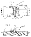
- the mounting flange is positioned with its locking pins 44, one shown in phantom lines in Fig. 3, adjacent to the leading edge of the slot 30 in the flange 29.
- a slight forward pressure is then applied to the mounting flange 12, and the flange is rotated in a clockwise direction as indicated by arrow 42 in Fig. 1, causing the locking pins 44 to ride along the angular ramps 34 seen in Figs. 5 and 6.
- the sealing ring 28 is substantially axially compressed.
- the 90° counterclockwise rotation locates the projections 38 on the flange to a release position wherein the projections are in alignment with the arcuate slots 30 in the connector body flange 29.
- the mounting flange 12 can then be readily slid off the rear of the connector body.
- the angular ramps 34, locking pins 44, recesses 32, and sealing ring 28 cooperate to form a detent mechanism 54 (Fig. 3) which releasably locks the mounting flange on the connector body, and permits easy removal of the flange from the body.
- the elastomeric ring 28 serves two functions, namely, as part of the detent mechanism, and also seals the mounting flange 12 to the connector body 14.
- the connector body 14 may be used as a cable connector, or may be modified to have the mounting flange 12 releasably mounted thereon to convert the cable connector to a flange mount connector for mounting to a panel.
- the sealing ring 28 could be replaced by any form of spring, such as an annular split wave washer that would be mounted in the groove 22 adjacent to the shoulder 24.
- the locking pins could be mounted on the annular flange 29 of the connector body extending in a forward direction, and the angular ramps 34 and pin-receiving recesses 32 could be formed in the rear surface of the mounting flange 12.
- the mounting flange has been described as being formed of plastic, it could also be formed of metal, and the plastic connector body 14 could be replaced by a metal connector shell containing an insulator in which the contact passages 16 are formed.
Landscapes
- Connector Housings Or Holding Contact Members (AREA)
Claims (5)
- Steckverbinder, enthaltend einen allgemein zylindrischen Steckverbinderkörper (14) mit einer Längsachse (A), dafür ausgelegt, dass er mindestens einen Kontakt und einen an dem Körper axial montierten Befestigungsflansch (12) enthält, gekennzeichnet durch :die Tatsache, dass der Körper eine ringförmige Nut (22) in sich aufweist, die einen ersten und einen zweiten einander gegenüberliegenden Absatz (24, 26) bildet, die hauptsächlich in Rückwärts- bzw. Vorwärtsrichtung weisen;einen elastischen Dichtring (28), der den Körper umgibt und in der Nut dem ersten Absatz (24) benachbart montiert ist;einen Befestigungsflansch (12), der eine weitgehend kreisförmige Öffnung (36) darin hat, die so dimensioniert ist, dass sie zulässt, dass der Flansch einen axialen Gleitsitz auf dem Körper von dessen Rückseite hat;mindestens einen in dem Körper von der Nut nach hinten verlaufenden Schlitz (30);wobei der Befestigungsflansch um die Achse zwischen einer unverriegelten Position und einer verriegelten Position drehbar ist und der Befestigungsflansch (12) einen nach innen verlaufenden Abschnitt (38) aufweist, der so geformt ist, dass er durch den in der Nut (22) angeordneten Schlitz (30) tritt und axial zwischen dem Dichtring und dem zweiten Absatz (26) liegt; und
einen Arretiermechanismus (54), der den elastischen Ring (28) enthält und der den Befestigungsflansch an dem Körper lösbar verriegelt, wenn der Befestigungsflansch um die Achse in eine vorbestimmte Position gedreht ist, wobei der Vorsprung (38) in der Nut (22) hinter dem nach vorne weisenden zweiten Absatz (26) und einer in dem zweiten Absatz (26) gebildeten Ausnehmung (32) angeordnet ist, die in einem vorbestimmten Abstand oder Winkel in Kreisrichtung in einer Richtung von dem Schlitz (30) beabstandet ist und mit einem Verriegelungsstift (44) in Eingriff kommt, der von dem Flansch nach hinten verläuft. - Steckverbinder nach Anspruch 1, bei welchem:der Körper entgegengesetzte Enden (18, 20) hat, ein bogenförmiger Schlitz (30) in dem Körper von der Nut (22) zu einem Ende (20) des Körpers verläuft, um axial verschieblich den nach innen verlaufenden Abschnitt (38) des Befestigungsflansches aufzunehmen, wenn der Befestigungsflansch (12) von dem einen Ende an dem Körper axial angebracht wird.
- Steckverbinder nach Anspruch 2, bei welchem:der zweite Absatz (26) nach vorne weist (F);eine im Winkel verlaufende Schräge (34) von dem Schlitz zu der Ausnehmung verläuft und eine Oberfläche bildet, auf der der Stift (44) läuft, wenn der Befestigungsflansch in die verriegelte Position gedreht wird; undder Dichtring (28) axial zusammengedrückt wird, wenn der Befestigungsflansch (12) in der einen Richtung in seine verriegelte Position gedreht wird, welcher Dichtring den Verriegelungsstift (44) in die Ausnehmung drückt, wenn der Befestigungsflansch in die verriegelte Position gedreht ist.
- Steckverbinder nach Anspruch 2, bei welchem:der elastische Ring (28) ein Elastomerring ist;der Befestigungsflansch (12) eine mit der Achse koaxiale zylindrische Wand (52) hat, die den Elastomerring (28) umgibt, wobei der Elastomerring in abdichtendem Eingriff mit der Innenfläche der zylindrischen Wand liegt.
- Steckverbinder nach Anspruch 1, bei welchem:der Körper einander entgegengesetzt ein vorderes und ein hinteres Ende (18, 20) aufweist und ein bogenförmiger Schlitz (30) in dem Körper von der Nut (22) nach hinten zu dem hinteren Ende (20) des Körpers verläuft, um axial verschieblich den nach innen verlaufenden Abschnitt (38) des Befestigungsflansches darin aufzunehmen, wenn der Befestigungsflansch (12) auf dem Körper von dem hinteren Ende axial nach vorne bewegt wird.
Applications Claiming Priority (2)
| Application Number | Priority Date | Filing Date | Title |
|---|---|---|---|
| US900557 | 1997-07-25 | ||
| US08/900,557 US6083040A (en) | 1997-07-25 | 1997-07-25 | Connector with releasable mounting flange |
Publications (3)
| Publication Number | Publication Date |
|---|---|
| EP0893852A2 EP0893852A2 (de) | 1999-01-27 |
| EP0893852A3 EP0893852A3 (de) | 1999-11-10 |
| EP0893852B1 true EP0893852B1 (de) | 2007-07-18 |
Family
ID=25412712
Family Applications (1)
| Application Number | Title | Priority Date | Filing Date |
|---|---|---|---|
| EP98113541A Expired - Lifetime EP0893852B1 (de) | 1997-07-25 | 1998-07-21 | Verbinder mit lösbarem Befestigungsflansch |
Country Status (3)
| Country | Link |
|---|---|
| US (1) | US6083040A (de) |
| EP (1) | EP0893852B1 (de) |
| DE (1) | DE69838082T2 (de) |
Cited By (1)
| Publication number | Priority date | Publication date | Assignee | Title |
|---|---|---|---|---|
| US7972154B2 (en) | 2006-05-11 | 2011-07-05 | Abl Sursum Bayerische Elektrozubehor Gmbh & Co. Kg | Rotatable feed |
Families Citing this family (34)
| Publication number | Priority date | Publication date | Assignee | Title |
|---|---|---|---|---|
| US6334715B1 (en) * | 1998-12-24 | 2002-01-01 | Bti, Photonics, Inc. | Mountable optical fibre couplers |
| DE19932113B4 (de) * | 1999-07-09 | 2005-12-15 | Audi Ag | Elektrische Steckverbindung |
| FI109564B (fi) * | 2000-11-24 | 2002-08-30 | Valtimo Components Oy | Radiotaajuusliitin |
| US6508666B1 (en) * | 2002-02-08 | 2003-01-21 | Delphi Technologies, Inc. | Pass-thru electrical connector assembly |
| DE20204382U1 (de) * | 2002-03-20 | 2003-07-31 | Adels-Contact Elektrotechnische Fabrik GmbH & Co KG, 51469 Bergisch Gladbach | Gehäuse mit einem Trägerelement für ein Anschlußelement |
| KR101176817B1 (ko) * | 2003-04-07 | 2012-08-24 | 가부시키가이샤 니콘 | 노광장치 및 디바이스 제조방법 |
| US7175481B1 (en) | 2005-11-01 | 2007-02-13 | Walbro Engine Management, L.L.C. | Sealed pass-through electrical connector |
| FR2888677B1 (fr) * | 2005-07-12 | 2010-12-10 | Radiall Sa | Ensemble de connexion electrique |
| DE102005062545A1 (de) * | 2005-12-27 | 2007-07-05 | Robert Bosch Gmbh | Steckverbindungsanordnung |
| DE102006053477C5 (de) * | 2006-11-14 | 2011-05-05 | Erich Jaeger Gmbh & Co. Kg | Steckdose |
| DE202006017885U1 (de) * | 2006-11-22 | 2007-03-08 | Coninvers Elektrotechnische Bauelemente Gmbh | Elektrischer Steckverbinder zur Wandbefestigung |
| DE202006018110U1 (de) * | 2006-11-29 | 2007-02-08 | Anton Hummel Verwaltungs-Gmbh | Steckverbinder für Vorderwandmontage oder Hinterwandmontage |
| JP4153549B1 (ja) * | 2007-06-28 | 2008-09-24 | タイコエレクトロニクスアンプ株式会社 | 防水型コネクタ、防水型コネクタの実装構造、および防水型コネクタの実装方法 |
| US7484982B1 (en) * | 2007-08-31 | 2009-02-03 | The Gillette Company | Coupling for a hand held appliance |
| KR100997863B1 (ko) * | 2008-04-04 | 2010-12-01 | 엘에스전선 주식회사 | 기기접속용 케이블 커넥터 및 이를 위한 기기접속유닛 |
| US7540768B1 (en) * | 2008-07-22 | 2009-06-02 | Ying-Cou Wang | Rotatable wall panel assembly for media signal wire |
| US8487196B1 (en) | 2009-06-26 | 2013-07-16 | Hubbell Incorporated | Box connector for electrical cable |
| DE202010002633U1 (de) * | 2010-02-22 | 2010-06-17 | THÖRNER, Wolfgang B. | Lagervorrichtung für eine Polklemme |
| US8550859B2 (en) * | 2011-10-20 | 2013-10-08 | Andrew Llc | Close proximity panel mount connectors |
| US8668506B2 (en) * | 2011-04-27 | 2014-03-11 | Lear Corporation | Charger receptacle |
| NL2007599C2 (en) * | 2011-10-14 | 2013-04-16 | Voltea Bv | Apparatus and method for removal removal of ions. |
| JP5854538B2 (ja) * | 2012-03-01 | 2016-02-09 | モレックス エルエルシー | パネルコネクタ |
| USD829891S1 (en) | 2012-12-14 | 2018-10-02 | Retractable Technologies, Inc. | Syringe with offset needle retraction chamber and frontal attachment |
| DE102013008765B4 (de) * | 2013-05-23 | 2017-06-01 | Amphenol-Tuchel Electronics Gmbh | Steckverbinder mit trennbaren Haltemitteln |
| DK2835878T3 (da) * | 2013-08-05 | 2019-06-24 | Phoenix Contact Connector Tech Gmbh | Indkapslet skrue forbindelse for en elektrisk terminal |
| CN104425986B (zh) * | 2013-09-11 | 2018-09-07 | 深圳富泰宏精密工业有限公司 | 电子装置 |
| US9553440B2 (en) | 2013-11-18 | 2017-01-24 | Walbro Llc | Wire seal assembly |
| US10326194B2 (en) | 2013-12-12 | 2019-06-18 | Schneider Electric USA, Inc. | Antenna mount for electrical panel boards |
| CN106602338A (zh) * | 2016-12-23 | 2017-04-26 | 深圳市宝尔爱迪科技有限公司 | 防水耳机插头固定机构及使用该结构的手机 |
| US10090659B2 (en) | 2017-02-16 | 2018-10-02 | Bridgeport Fittings, Inc. | Raintight fitting for jacketed metal clad cables |
| WO2021102117A1 (en) * | 2019-11-22 | 2021-05-27 | Spectrum Brands, Inc. | Sealing of an electronic lock |
| CN112510406A (zh) * | 2020-11-25 | 2021-03-16 | 泰兴市航安电器有限公司 | 一种一体式可提高传输效率的圆形电连接器 |
| JP2022149207A (ja) | 2021-03-25 | 2022-10-06 | 住友電装株式会社 | パネル取付型コネクタ |
| DE102021109407A1 (de) | 2021-04-14 | 2022-10-20 | Endress + Hauser Flowtec Ag | Steckverbindung für hochfrequenzbasierte Feldgeräte |
Family Cites Families (16)
| Publication number | Priority date | Publication date | Assignee | Title |
|---|---|---|---|---|
| US3398391A (en) * | 1967-08-10 | 1968-08-20 | Alexander R. Brishka | Hermetically sealed connectors |
| US3430187A (en) * | 1968-03-11 | 1969-02-25 | Heiko T De Man | Marine plug |
| US3818420A (en) * | 1970-12-07 | 1974-06-18 | Itt | Low insertion force electrical connector |
| BE788766A (fr) * | 1971-09-23 | 1973-01-02 | Bunker Ramo | Assemblages de traversee electriques |
| US3719918A (en) * | 1971-11-04 | 1973-03-06 | Schlumberger Technology Corp | Electrical connector |
| US3772637A (en) * | 1972-02-16 | 1973-11-13 | Amp Inc | Device for sealing electrical connectors |
| US3790698A (en) * | 1972-07-25 | 1974-02-05 | Chance Co | Detachable bushing |
| DE2329334A1 (de) * | 1973-06-08 | 1975-01-02 | Daimler Benz Ag | Zentralsteckverbindung |
| US3982813A (en) * | 1975-11-19 | 1976-09-28 | General Motors Corporation | Weather sealed lamp socket assembly |
| US4066314A (en) * | 1976-06-28 | 1978-01-03 | Williams Robert A | Electrical connector backshell accessory indexing body |
| US4193655A (en) * | 1978-07-20 | 1980-03-18 | Amp Incorporated | Field repairable connector assembly |
| US4427255A (en) * | 1979-11-14 | 1984-01-24 | General Electric Company | Plastic based glass halogen lamp |
| US5035646A (en) * | 1990-06-29 | 1991-07-30 | Hubbell Incorporated | Flush mounted receptacle and plug with pin and sleeve type contacts |
| JP2779104B2 (ja) * | 1992-11-12 | 1998-07-23 | 日本原子力研究所 | 簡易着脱電気コネクター |
| GB9316838D0 (en) * | 1993-08-13 | 1993-09-29 | Amp Gmbh | Circular bulkhead connector assembly |
| JPH0945444A (ja) * | 1995-07-28 | 1997-02-14 | Yazaki Corp | ランプソケット用防水構造 |
-
1997
- 1997-07-25 US US08/900,557 patent/US6083040A/en not_active Expired - Fee Related
-
1998
- 1998-07-21 DE DE69838082T patent/DE69838082T2/de not_active Expired - Fee Related
- 1998-07-21 EP EP98113541A patent/EP0893852B1/de not_active Expired - Lifetime
Cited By (1)
| Publication number | Priority date | Publication date | Assignee | Title |
|---|---|---|---|---|
| US7972154B2 (en) | 2006-05-11 | 2011-07-05 | Abl Sursum Bayerische Elektrozubehor Gmbh & Co. Kg | Rotatable feed |
Also Published As
| Publication number | Publication date |
|---|---|
| EP0893852A2 (de) | 1999-01-27 |
| DE69838082D1 (de) | 2007-08-30 |
| US6083040A (en) | 2000-07-04 |
| EP0893852A3 (de) | 1999-11-10 |
| DE69838082T2 (de) | 2008-04-10 |
Similar Documents
| Publication | Publication Date | Title |
|---|---|---|
| US6083040A (en) | Connector with releasable mounting flange | |
| US4165910A (en) | Electrical connector | |
| EP0638965B1 (de) | Runde Durchführungsverbinderanordnung | |
| US4462653A (en) | Electrical connector assembly | |
| US4464001A (en) | Coupling nut having an anti-decoupling device | |
| EP0052530B1 (de) | Kupplungsring eines elektrischen Verbinders mit angeformter Feder | |
| US5399096A (en) | Electrical connector having a threaded ring and means for retaining it in locked condition | |
| US4478473A (en) | Coupling nut for an electrical connector | |
| US4484790A (en) | Anti-decoupling device for an electrical connector | |
| US4074927A (en) | Electrical connector with insert member retaining means | |
| EP0210272A1 (de) | Kupplungsvorrichtung für verbinder | |
| US5993266A (en) | Keying system for electrical connector | |
| KR950002113A (ko) | 변형이 감소된 케이블 커넥터 | |
| GB1595968A (en) | Electrical connector with arcuate detent means | |
| US4154496A (en) | Coupling assembly for resilient electrical connector components | |
| GB1595967A (en) | Electrical connector and frequency shielding means therefor | |
| GB1585438A (en) | Electrical connector assembly having antidecoupling mechanism | |
| GB2236221A (en) | Rotary lanyard-disconnected electrical connector | |
| US4542952A (en) | Electrical connector assembly having locking means | |
| CA1296079C (en) | Locked connector | |
| US4500154A (en) | Electrical connector assembly having an anti-decoupling device | |
| EP0708496A2 (de) | Elektrische Verbinderanordnung mit verbessertem Entkupplungsverzögerungsmechanismus | |
| US4462652A (en) | Coupling nut for an electrical connector | |
| EP0892466B1 (de) | Elektrischer Steckverbinder | |
| US20020048984A1 (en) | Electrical plug connector half |
Legal Events
| Date | Code | Title | Description |
|---|---|---|---|
| PUAI | Public reference made under article 153(3) epc to a published international application that has entered the european phase |
Free format text: ORIGINAL CODE: 0009012 |
|
| AK | Designated contracting states |
Kind code of ref document: A2 Designated state(s): DE FR GB IT SE |
|
| AX | Request for extension of the european patent |
Free format text: AL;LT;LV;MK;RO;SI |
|
| PUAL | Search report despatched |
Free format text: ORIGINAL CODE: 0009013 |
|
| AK | Designated contracting states |
Kind code of ref document: A3 Designated state(s): AT BE CH CY DE DK ES FI FR GB GR IE IT LI LU MC NL PT SE |
|
| AX | Request for extension of the european patent |
Free format text: AL;LT;LV;MK;RO;SI |
|
| 17P | Request for examination filed |
Effective date: 20000510 |
|
| AKX | Designation fees paid |
Free format text: DE FR GB IT SE |
|
| 17Q | First examination report despatched |
Effective date: 20030926 |
|
| GRAP | Despatch of communication of intention to grant a patent |
Free format text: ORIGINAL CODE: EPIDOSNIGR1 |
|
| GRAS | Grant fee paid |
Free format text: ORIGINAL CODE: EPIDOSNIGR3 |
|
| GRAA | (expected) grant |
Free format text: ORIGINAL CODE: 0009210 |
|
| AK | Designated contracting states |
Kind code of ref document: B1 Designated state(s): DE FR GB IT SE |
|
| REG | Reference to a national code |
Ref country code: GB Ref legal event code: FG4D |
|
| REG | Reference to a national code |
Ref country code: SE Ref legal event code: TRGR |
|
| REF | Corresponds to: |
Ref document number: 69838082 Country of ref document: DE Date of ref document: 20070830 Kind code of ref document: P |
|
| ET | Fr: translation filed | ||
| PLBE | No opposition filed within time limit |
Free format text: ORIGINAL CODE: 0009261 |
|
| STAA | Information on the status of an ep patent application or granted ep patent |
Free format text: STATUS: NO OPPOSITION FILED WITHIN TIME LIMIT |
|
| 26N | No opposition filed |
Effective date: 20080421 |
|
| PGFP | Annual fee paid to national office [announced via postgrant information from national office to epo] |
Ref country code: DE Payment date: 20080829 Year of fee payment: 11 |
|
| PGFP | Annual fee paid to national office [announced via postgrant information from national office to epo] |
Ref country code: IT Payment date: 20080725 Year of fee payment: 11 Ref country code: FR Payment date: 20080729 Year of fee payment: 11 |
|
| PGFP | Annual fee paid to national office [announced via postgrant information from national office to epo] |
Ref country code: GB Payment date: 20080729 Year of fee payment: 11 |
|
| PGFP | Annual fee paid to national office [announced via postgrant information from national office to epo] |
Ref country code: SE Payment date: 20080729 Year of fee payment: 11 |
|
| EUG | Se: european patent has lapsed | ||
| GBPC | Gb: european patent ceased through non-payment of renewal fee |
Effective date: 20090721 |
|
| REG | Reference to a national code |
Ref country code: FR Ref legal event code: ST Effective date: 20100331 |
|
| PG25 | Lapsed in a contracting state [announced via postgrant information from national office to epo] |
Ref country code: FR Free format text: LAPSE BECAUSE OF NON-PAYMENT OF DUE FEES Effective date: 20090731 |
|
| PG25 | Lapsed in a contracting state [announced via postgrant information from national office to epo] |
Ref country code: GB Free format text: LAPSE BECAUSE OF NON-PAYMENT OF DUE FEES Effective date: 20090721 |
|
| PG25 | Lapsed in a contracting state [announced via postgrant information from national office to epo] |
Ref country code: DE Free format text: LAPSE BECAUSE OF NON-PAYMENT OF DUE FEES Effective date: 20100202 |
|
| PG25 | Lapsed in a contracting state [announced via postgrant information from national office to epo] |
Ref country code: IT Free format text: LAPSE BECAUSE OF NON-PAYMENT OF DUE FEES Effective date: 20090721 |
|
| PG25 | Lapsed in a contracting state [announced via postgrant information from national office to epo] |
Ref country code: SE Free format text: LAPSE BECAUSE OF NON-PAYMENT OF DUE FEES Effective date: 20090722 |