EP0708588B1 - Dispositif de decoupe d'une ou plusieurs plaques de gazon et procede d'empilage de ces plaques - Google Patents
Dispositif de decoupe d'une ou plusieurs plaques de gazon et procede d'empilage de ces plaques Download PDFInfo
- Publication number
- EP0708588B1 EP0708588B1 EP94924419A EP94924419A EP0708588B1 EP 0708588 B1 EP0708588 B1 EP 0708588B1 EP 94924419 A EP94924419 A EP 94924419A EP 94924419 A EP94924419 A EP 94924419A EP 0708588 B1 EP0708588 B1 EP 0708588B1
- Authority
- EP
- European Patent Office
- Prior art keywords
- grass
- conveyor
- sods
- sod
- cutting
- Prior art date
- Legal status (The legal status is an assumption and is not a legal conclusion. Google has not performed a legal analysis and makes no representation as to the accuracy of the status listed.)
- Expired - Lifetime
Links
- 244000025254 Cannabis sativa Species 0.000 title claims description 93
- 238000005520 cutting process Methods 0.000 title claims description 42
- 238000000034 method Methods 0.000 title claims description 9
- 240000002459 Urochloa reptans Species 0.000 claims 2
- 230000008878 coupling Effects 0.000 claims 1
- 238000010168 coupling process Methods 0.000 claims 1
- 238000005859 coupling reaction Methods 0.000 claims 1
- 230000032258 transport Effects 0.000 description 5
- 238000005096 rolling process Methods 0.000 description 4
- 230000001360 synchronised effect Effects 0.000 description 2
- 241000526657 Microchloa Species 0.000 description 1
- 230000001419 dependent effect Effects 0.000 description 1
- 239000012467 final product Substances 0.000 description 1
- 238000004519 manufacturing process Methods 0.000 description 1
- 230000007246 mechanism Effects 0.000 description 1
- 238000009331 sowing Methods 0.000 description 1
- 229920002994 synthetic fiber Polymers 0.000 description 1
Images


Classifications
-
- A—HUMAN NECESSITIES
- A01—AGRICULTURE; FORESTRY; ANIMAL HUSBANDRY; HUNTING; TRAPPING; FISHING
- A01G—HORTICULTURE; CULTIVATION OF VEGETABLES, FLOWERS, RICE, FRUIT, VINES, HOPS OR SEAWEED; FORESTRY; WATERING
- A01G20/00—Cultivation of turf, lawn or the like; Apparatus or methods therefor
- A01G20/10—Pre-cultivated sod or turf; Apparatus therefor
- A01G20/12—Apparatus for cutting sods or turfs
- A01G20/15—Apparatus for cutting sods or turfs specially adapted for stacking sods or sod rolls
-
- Y—GENERAL TAGGING OF NEW TECHNOLOGICAL DEVELOPMENTS; GENERAL TAGGING OF CROSS-SECTIONAL TECHNOLOGIES SPANNING OVER SEVERAL SECTIONS OF THE IPC; TECHNICAL SUBJECTS COVERED BY FORMER USPC CROSS-REFERENCE ART COLLECTIONS [XRACs] AND DIGESTS
- Y10—TECHNICAL SUBJECTS COVERED BY FORMER USPC
- Y10S—TECHNICAL SUBJECTS COVERED BY FORMER USPC CROSS-REFERENCE ART COLLECTIONS [XRACs] AND DIGESTS
- Y10S414/00—Material or article handling
- Y10S414/124—Roll handlers
Definitions
- the present invention provides a method for cutting out and stacking up one or more grass sods, as defined in claim 1.
- a method which makes it possible to cut out and stack up grass sods in such a manner that a similar grass sod can be pulled of the stacked up grass sods with a relatively simple help means or with the hand, and placed then at the desired place.
- the present invention provides an apparatus for cutting grass sods out of grass land and for stacking to a predetermined quantity one or more grass sods, as defined in claim 4.
- Particular embodiments of the method and apparatus are defined in the dependent claims.
- the base concept of the present invention aims to provide a universal grass sod cutting apparatus which can process big rolls as well as stacked grass sods in other ways. Due to the working costs and level of training needed for personnel working on the land, the automatic laying down (and therefore also the manufacturing of) large rolls of grass sods is more or less desired.
- a cutting head 5 is secured in frame 2 which is preferably changeable and suspended somewhat moveable in the frame 2, so that this cutting head 5 can follow possible irregularities in the ground surface level and can thus cut out grass sods of near enough uniform thickness. Details of a cutting head for cutting out grass sods are described in the older patent US-A-4.892.152 of the applicant. Although the cutting head 5 is capable of cutting out grass sods with a breadth of 48 inches, 120 cm or for instance 1 meter, one or more narrower strips of grass can also be cut out with another cutting head.
- a first conveyor 6 is secured behind the cutting head for transporting the grass sods upwards from the cutting head (see arrow W).
- a second conveyor 7 is also secured on the frame 2 which in the position shown in figures 1 and 2 connects to the conveyor 6 and transports the grass sods further in an upwards direction (arrow B) whereafter these are transported downwards between these conveyors 8 or 9, which both form part of the second conveyor 7, and are stacked on a pallet P.
- the pallet P is shifted onto a fork 10, which is secured to a frame part 11, which according to arrow C is moveable in an upwards and downwards direction in accordance with the height of the grass sods G already stacked.
- the part conveyors 8 and 9 are swivelable to and fro, as depicted by broken arrow D, by means of a hydraulicly operable plunger 13 so that the grass sods are stacked onto pallet P in a zig-zag manner.
- a grass sod stacked in such a zig-zag manner can be lain out by simply pulling on the upperside thereof, if the strength of the grass sod allows this.
- an approaching sensor is for instance mounted on the underside of one of the conveyors 8, 9 which is workably connected with a schematically shown device 14 for lowering the fork 10 and thereby the pallet P with regularity, so that the distance between the underside of the part conveyors 8, 9 and the upper side of the grass sod G remains roughly constant.
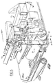
- the conveyor 6 is brought into a low position by means of hydraulic cylinders 20, 21 and there behind are two help conveyors 22 in the transporting direction of the conveyor 6.
- the first conveyor 6 and the part conveyors 22 and 23 belonging thereto work together with the part conveyors 8 and 9 which belong to the second conveyor 7.
- FIG 3 is, above all, schematically depicted how with the aid of a driving belt 24, of which the length by means of an adjusting member 25 secured to the frame 26, is adjustable, the synchronization of the driving of the conveyors takes place.
- the part conveyors 8 and 9 are driven via the driving belt 24 and the fixed head part of the second conveyor 7 whilst the help conveyors 22 and 23 are driven via driving belt 24 and the head part of the first conveyor 6.
- the help conveyors 22, 23 are respectively folded away under the main part of the first conveyor 6 and the driving belt 24 is so adjusted, with the aid of the adjusting element 25, that synchronization again takes place between the first and second conveyors 6, 7 respectively.
- FIG 4 It is also shown in figure 4 that the driving of the first conveyor 6 and second conveyor 7 is synchronized by means of the driving belt 24.
- a schematically depicted driving belt 40 is also seen in figure 4 which guarantees the synchronization of the conveyors 8 and 9 with the first conveyor 6.
- a hydraulic system is preferably used, which preferably makes use of a power take off 41 of a further not shown puller.
- a hydraulic unit 42 is connected thereon, with which the driving of the diverse driving belts and other hydraulic cylinders depicted in figure 4 is taken care of.
- the to and fro movement of the part conveyors 8 and 9 via plunger 13 and the therewith belonging cylinder 42 is of particular importance.
- a pulley 44, along which the driving belt 40 is guided, is workably coupled with a hydraulic operating member 45 for operating plunger 13 via the hydraulic cylinder 43.
- the cutting head 5 is shown in more detail in figure 5 so as it is placed in the frame 2 in the embodiments shown in figures 1-4.
- This cutting head is, apart from the large breadth thereof for cutting out of earlier mentioned breadths of 120 cm, in many ways similar to the cutting head as shown and described in the earlier mentioned American patent of the applicant.
- a knife 52 is, according to arrow I with respect to a roll 53, adjustable for adjusting the thickness of a sod to be cut.
- a vertically moveable knife 53 is also mounted which determines the length of grass sod to be cut during operation. It is also conceivable to place a cutting-off knife near to the first or second conveyor for cutting off of the sod length.
- Punch elements 55 are placed in front of the roll 43 and under the knife 52 on the frame part 54 which punches a relatively small part of the grass land into the ground before a grass sod is cut out of the grass land. Under certain climatological circumstances is it sufficient that such relatively small parts of the grass land remain behind so that the grass land does not need to be further sown. It is also conceivable under these climatological circumstances and suitable grass sorts therefor, to leave behind small grass strips in the grass land wherefrom a complete grass land then grows.
- each knife for the cutting out of the narrower grass sods, is suspended independently in the cutting head so that each cutting head can follow possible irregularities in the level of the grass land and cut out sods of as much as possible consistent thickness.
- the second conveyor 7 is also easily interchangeably secured in the frame, it is for both broader and narrower grass strips possible to determine the manner of stacking onto the pallets according to the wishes of the customer.
- the narrow or broad grass strips can, according to wishes, by means of a vertically moveable knife such as the knife 56 in figure 5, be cut out with a determined length.
- the second conveyor can for instance be made up of two or three conveyors mounted above each other which are successively provided with a grass sod, due to the fact that the first conveyor 1 is moved up and down to a certain extent, whereafter each of the part conveyors can bring a smaller or bigger grass sod, whether or not folded, onto a pallet.
- FIG 6 a grass sod G, folded in a zig-zag manner, on a pallet P is shown, i.e. the final product of the preferred embodiment shown in figure 1 of the present invention in the position as shown in figure 1 and 2.
- a large roll 70 is obtained with the apparatus according to the present invention in the position as shown in figure 2.
- cut out grass sods G' with a breadth of 120 cm for example are repeatedly stacked onto each other.
- first and second conveyors can then be set up as one passing through conveyor.
- an apparatus can be easily made suitable for cutting out of narrow grass sods according to the requirements of the user of the apparatus.
- An important new aspect here is that with narrower grass sods a strip of grass can be left behind on the grass land, because under certain climatological circumstances the sowing of new grass need not be carried out because new grass land can form from the grass strip left behind.
- the conveyor can be provided with discs or baffle plates in order to bring the narrow grass strips into the desired mutual positions on the broad conveyor.
Landscapes
- Life Sciences & Earth Sciences (AREA)
- Environmental Sciences (AREA)
- Harvester Elements (AREA)
- Cultivation Of Plants (AREA)
- Soil Working Implements (AREA)
Claims (10)
- Procédé de découpe et d'empilage d'une ou plusieurs plaques de gazon (G) dans lequel une première partie d'une plaque de gazon (G) est placée sur un support (P) approprié, après quoi la plaque de gazon (G) est pliée et une seconde partie de la plaque de gazon (G) est placée sur la première partie, caractérisé en ce que la plaque de gazon (G) est pliée à plusieurs reprises pour donner une plaque de gazon (G), à défilement continu, empilée en accordéon, ladite plaque de gazon (G), à défilement continu, comprenant au moins deux plis.
- Procédé selon la revendication 1 dans lequel la plaque de gazon (G) est automatiquement pliée à plusieurs reprises par une machine.
- Procédé selon la revendication 1 dans lequel la plaque de gazon (G) a une largeur d'environ 60 à 120 cm.
- Appareil pour découper des plaques de gazon (G) dans un terrain gazonné et pour empiler une ou plusieurs plaques de gazon (G) en quantité prédéterminée, comprenant :un châssis (2) doté de deux ou plusieurs roues suspendues à celui-ci;une tête de découpe (5) suspendue au châssis (2) pour découper les plaques de gazon (G) par en-dessous ;un transporteur (6, 7) monté sur le châssis (2) dans le sens d'entrâinement vu de derrière la tête de coupe (5) qui sert à transporter de manière répétée les plaques (G) vers le haut depuis la tête de coupe (5);une partie effectuant un mouvement alternatif (8, 9) qui est fixée à l'extrémité du transporteur (6, 7);
caractérisé en ce que ladite partie effectuant un mouvement alternatif (8, 9) empile les plaques de gazon suivant un mouvement alternatif vers le bas depuis le transporteur (6, 7) sur un support de stockage (P) en accordéon, et en ce que la partie effectuant un mouvement alternatif (8, 9) est mobile entre une première position d'empilage des plaques de gazon et une seconde position d'empilage des plaques de gazon au moyen d'un arrangement de tige de piston (13) fixé à celle-ci. - Appareil selon la revendication 4, qui est agencé sur le côté avant avec un arbre (3) pour le couplage à un tracteur.
- Appareil selon les revendications 4 ou 5, dans lequel deux roues dotées de pneus relativement larges sont associées de manière rotative aux deux côtés du châssis (2) du côté extérieur.
- Appareil selon les revendications 4, 5 ou 6 dans lequel la largeur du transporteur (6, 7) est d'au moins 48 pouces ou 120 cm.
- Appareil selon l'une quelconque des revendications 3 à 6 dans lequel la tête de découpe (5) est dotée de deux ou plusieurs couteaux de découpe agencés pour se déplacer les uns par rapport aux autres.
- Appareil selon l'une quelconque des revendications 4 à 8 dans lequel le transporteur (6, 7) dans une première position haute se raccorde à la partie effectuant un mouvement alternatif (8, 9) et dans la seconde position basse se raccorde à un transporteur auxiliaire (22, 23) faisant partie du transporteur (6, 7) pour transporter les plaques de gazon (G) sous la partie effectuant un mouvement alternatif (8, 9).
- Appareil selon l'une quelconque des revendications 4 à 9 dans lequel le transporteur (6, 7) est dotée d'un ou plusieurs transporteurs auxiliaires (22, 23) pour transporter de manière répétée les plaques de gazon (G) vers l'arrière à un niveau inférieur à celui de la partie effectuant un mouvement alternatif (8, 9).
Applications Claiming Priority (3)
| Application Number | Priority Date | Filing Date | Title |
|---|---|---|---|
| NL9301218 | 1993-07-12 | ||
| NL9301218A NL9301218A (nl) | 1993-07-12 | 1993-07-12 | Inrichting voor het snijden van één of meer graszoden en werkwijze voor het stapelen daarvan. |
| PCT/NL1994/000159 WO1995002317A1 (fr) | 1993-07-12 | 1994-07-12 | Dispositif de decoupe d'une ou plusieurs plaques de gazon et procede d'empilage de ces plaques |
Publications (2)
| Publication Number | Publication Date |
|---|---|
| EP0708588A1 EP0708588A1 (fr) | 1996-05-01 |
| EP0708588B1 true EP0708588B1 (fr) | 1998-12-23 |
Family
ID=19862646
Family Applications (1)
| Application Number | Title | Priority Date | Filing Date |
|---|---|---|---|
| EP94924419A Expired - Lifetime EP0708588B1 (fr) | 1993-07-12 | 1994-07-12 | Dispositif de decoupe d'une ou plusieurs plaques de gazon et procede d'empilage de ces plaques |
Country Status (5)
| Country | Link |
|---|---|
| US (1) | US5857527A (fr) |
| EP (1) | EP0708588B1 (fr) |
| DE (1) | DE69415530T2 (fr) |
| NL (1) | NL9301218A (fr) |
| WO (1) | WO1995002317A1 (fr) |
Families Citing this family (12)
| Publication number | Priority date | Publication date | Assignee | Title |
|---|---|---|---|---|
| US6273196B1 (en) * | 1993-07-12 | 2001-08-14 | Harmelerwaard Patents B.V. | Apparatus and method for the stacking of cut grass sods |
| US6244354B1 (en) | 1995-09-15 | 2001-06-12 | Harmelerwaard Patents B.V. | Device and process for cutting grass sods with a constant thickness from grass land |
| NL1005247C2 (nl) | 1996-08-30 | 1998-03-11 | Harmelerwaard Patents Bv | Werkwijze en inrichting voor het leggen en/of opnemen van relatief grote en dikke graszoden. |
| US6131668A (en) * | 1997-12-29 | 2000-10-17 | Clark Equipment Company | Sod laying apparatus and method |
| DE19959432B4 (de) | 1999-12-09 | 2004-02-26 | Osi International Foods Gmbh | Vorrichtung zur Herstellung von Hackfleischscheibenprodukten aus Rind- und/oder Schweinefleisch |
| US6659189B2 (en) * | 2001-02-23 | 2003-12-09 | Woerner Manufacturing, Inc. | Sod harvesting machine |
| US8235131B2 (en) | 2005-02-04 | 2012-08-07 | 1045929 Ontario Limited | Method and apparatus for harvesting and picking up sod |
| EP1850654A4 (fr) * | 2005-02-04 | 2015-12-16 | 1045929 Ontario Ltd | Procede et appareil pour le decoupage et le ramassage de plaques de gazon |
| US7516524B2 (en) * | 2005-03-11 | 2009-04-14 | Velcro Industries B.V. | Hook fastener components and methods of their manufacture |
| US10299443B1 (en) * | 2016-03-10 | 2019-05-28 | Trebro Holding, Inc. | Sod harvesters |
| AU2017257882B2 (en) * | 2016-04-29 | 2019-10-03 | Motz Enterprises, Inc. | System and method for rolling up a flexible sheet |
| CN107172900B (zh) * | 2017-05-27 | 2023-09-01 | 南京工业职业技术学院 | 一种全自动草皮收割机 |
Family Cites Families (15)
| Publication number | Priority date | Publication date | Assignee | Title |
|---|---|---|---|---|
| US3034586A (en) * | 1955-02-25 | 1962-05-15 | Sod Master Corp | Sod cutting knife |
| US3235011A (en) * | 1962-12-12 | 1966-02-15 | Richard A Pasinski | Sod roll forming machine |
| US3429377A (en) * | 1965-03-05 | 1969-02-25 | John F Nunes Jr | Sod harvesting apparatus |
| US3468381A (en) * | 1966-04-01 | 1969-09-23 | Marvin A Olson | Turfing tool |
| US3664432A (en) * | 1969-03-17 | 1972-05-23 | John F Nunes Jr | Sod handling apparatus |
| US3672452A (en) * | 1969-12-30 | 1972-06-27 | William W Miner | Apparatus for harvesting sod |
| US3887013A (en) * | 1974-06-24 | 1975-06-03 | Tri County Machine Products In | Sod cutting and stacking machine |
| US4063384A (en) * | 1976-03-25 | 1977-12-20 | Warren Turf Nursery, Inc. | Method of and apparatus for washing sod strips, and method of sodding with washed sod strips |
| US4162709A (en) * | 1977-07-21 | 1979-07-31 | Wilson-Miner R & D | Sod harvesting severing means for forming and orienting individual sod pads |
| US4162726A (en) * | 1977-07-21 | 1979-07-31 | Wilson-Miner R & D | Sod harvesting machine having means for conveying and stacking sod pads |
| US4294316A (en) * | 1980-04-25 | 1981-10-13 | Hedley Victor H | Sod cutting and stacking machine |
| US4408666A (en) * | 1981-10-28 | 1983-10-11 | Lawson Charles L | Sod handling apparatus |
| CA1260021A (fr) * | 1985-10-28 | 1989-09-26 | Brouwer Turf Equipment Limited | Dispositif et methode de recolte des plaques de gazon |
| US4828040A (en) * | 1987-07-30 | 1989-05-09 | Teledyne Princeton, Inc. | Side unloading automatic sod harvesting apparatus |
| US5064000A (en) * | 1990-10-30 | 1991-11-12 | Bucyrus Equipment Co., Inc. | Method of and apparatus for cutting sod which rolls in a semi-flaccid sheet into sod roll |
-
1993
- 1993-07-12 NL NL9301218A patent/NL9301218A/nl active Search and Examination
-
1994
- 1994-07-12 EP EP94924419A patent/EP0708588B1/fr not_active Expired - Lifetime
- 1994-07-12 WO PCT/NL1994/000159 patent/WO1995002317A1/fr not_active Ceased
- 1994-07-12 DE DE69415530T patent/DE69415530T2/de not_active Expired - Lifetime
-
1996
- 1996-01-16 US US08/585,632 patent/US5857527A/en not_active Expired - Lifetime
Also Published As
| Publication number | Publication date |
|---|---|
| US5857527A (en) | 1999-01-12 |
| NL9301218A (nl) | 1995-02-01 |
| WO1995002317A1 (fr) | 1995-01-26 |
| DE69415530T2 (de) | 1999-05-12 |
| EP0708588A1 (fr) | 1996-05-01 |
| DE69415530D1 (de) | 1999-02-04 |
Similar Documents
| Publication | Publication Date | Title |
|---|---|---|
| EP0708588B1 (fr) | Dispositif de decoupe d'une ou plusieurs plaques de gazon et procede d'empilage de ces plaques | |
| US9422129B2 (en) | Apparatus and methods for facilitating the removal of existing turf and installing new turf | |
| EP2697144B1 (fr) | Appareil et procédé pour faciliter l'enlèvement de gazon existant | |
| EP0573620B1 (fr) | Appareil servant a poser du gazon | |
| US8505643B2 (en) | Method and apparatus for harvesting and picking up sod | |
| US5571252A (en) | High frequency, low amplitude, sod harvesting apparatus | |
| CN207022760U (zh) | 一种全自动草皮收割机 | |
| US20250301969A1 (en) | Modular ultra low drag sub-surface membrane installation apparatus, machine, and methods with various automated and semi-automated sub-systems including sub-surface drip tape installation | |
| US5988289A (en) | Sod laying apparatus | |
| CA2166990C (fr) | Appareil servant au prelevement et a la mise en pile de plaques de gazon | |
| US3747686A (en) | Apparatus for harvesting sod | |
| CA2596924C (fr) | Procede et appareil pour le decoupage et le ramassage de plaques de gazon | |
| JPH0411803A (ja) | 除草方法及び除草機 | |
| WO1998021083A1 (fr) | Vehicule a bandes sans fin supportant un dispositif servant a distribuer du sable | |
| DE20318936U1 (de) | Einrichtung zum Verschieben von Ziegeln beispielsweise zwecks Bildung eines Stapels als Straßenbeschichtung benutzter Ziegel | |
| JP3332183B2 (ja) | 農産物収穫機 | |
| JPH04320613A (ja) | 茶葉摘採方法 |
Legal Events
| Date | Code | Title | Description |
|---|---|---|---|
| PUAI | Public reference made under article 153(3) epc to a published international application that has entered the european phase |
Free format text: ORIGINAL CODE: 0009012 |
|
| 17P | Request for examination filed |
Effective date: 19960112 |
|
| AK | Designated contracting states |
Kind code of ref document: A1 Designated state(s): BE DE FR GB NL |
|
| 17Q | First examination report despatched |
Effective date: 19970228 |
|
| GRAG | Despatch of communication of intention to grant |
Free format text: ORIGINAL CODE: EPIDOS AGRA |
|
| GRAG | Despatch of communication of intention to grant |
Free format text: ORIGINAL CODE: EPIDOS AGRA |
|
| GRAH | Despatch of communication of intention to grant a patent |
Free format text: ORIGINAL CODE: EPIDOS IGRA |
|
| GRAH | Despatch of communication of intention to grant a patent |
Free format text: ORIGINAL CODE: EPIDOS IGRA |
|
| GRAA | (expected) grant |
Free format text: ORIGINAL CODE: 0009210 |
|
| AK | Designated contracting states |
Kind code of ref document: B1 Designated state(s): BE DE FR GB NL |
|
| REF | Corresponds to: |
Ref document number: 69415530 Country of ref document: DE Date of ref document: 19990204 |
|
| ET | Fr: translation filed | ||
| PLBE | No opposition filed within time limit |
Free format text: ORIGINAL CODE: 0009261 |
|
| STAA | Information on the status of an ep patent application or granted ep patent |
Free format text: STATUS: NO OPPOSITION FILED WITHIN TIME LIMIT |
|
| 26N | No opposition filed | ||
| REG | Reference to a national code |
Ref country code: GB Ref legal event code: IF02 |
|
| PGFP | Annual fee paid to national office [announced via postgrant information from national office to epo] |
Ref country code: GB Payment date: 20120730 Year of fee payment: 19 |
|
| PGFP | Annual fee paid to national office [announced via postgrant information from national office to epo] |
Ref country code: DE Payment date: 20120730 Year of fee payment: 19 Ref country code: FR Payment date: 20120810 Year of fee payment: 19 Ref country code: BE Payment date: 20120730 Year of fee payment: 19 |
|
| PGFP | Annual fee paid to national office [announced via postgrant information from national office to epo] |
Ref country code: NL Payment date: 20120731 Year of fee payment: 19 |
|
| BERE | Be: lapsed |
Owner name: *VAN VUUREN JOHANNES Effective date: 20130731 |
|
| REG | Reference to a national code |
Ref country code: NL Ref legal event code: V1 Effective date: 20140201 |
|
| GBPC | Gb: european patent ceased through non-payment of renewal fee |
Effective date: 20130712 |
|
| REG | Reference to a national code |
Ref country code: FR Ref legal event code: ST Effective date: 20140331 |
|
| PG25 | Lapsed in a contracting state [announced via postgrant information from national office to epo] |
Ref country code: DE Free format text: LAPSE BECAUSE OF NON-PAYMENT OF DUE FEES Effective date: 20140201 Ref country code: BE Free format text: LAPSE BECAUSE OF NON-PAYMENT OF DUE FEES Effective date: 20130731 Ref country code: NL Free format text: LAPSE BECAUSE OF NON-PAYMENT OF DUE FEES Effective date: 20140201 Ref country code: GB Free format text: LAPSE BECAUSE OF NON-PAYMENT OF DUE FEES Effective date: 20130712 |
|
| REG | Reference to a national code |
Ref country code: DE Ref legal event code: R119 Ref document number: 69415530 Country of ref document: DE Effective date: 20140201 |
|
| PG25 | Lapsed in a contracting state [announced via postgrant information from national office to epo] |
Ref country code: FR Free format text: LAPSE BECAUSE OF NON-PAYMENT OF DUE FEES Effective date: 20130731 |