EP0708702B1 - Procede et appareil permettant de former un tuyau thermoplastique a double paroi a emboitements integres - Google Patents
Procede et appareil permettant de former un tuyau thermoplastique a double paroi a emboitements integres Download PDFInfo
- Publication number
- EP0708702B1 EP0708702B1 EP93914573A EP93914573A EP0708702B1 EP 0708702 B1 EP0708702 B1 EP 0708702B1 EP 93914573 A EP93914573 A EP 93914573A EP 93914573 A EP93914573 A EP 93914573A EP 0708702 B1 EP0708702 B1 EP 0708702B1
- Authority
- EP
- European Patent Office
- Prior art keywords
- parison
- mold
- balloons
- belled
- region
- Prior art date
- Legal status (The legal status is an assumption and is not a legal conclusion. Google has not performed a legal analysis and makes no representation as to the accuracy of the status listed.)
- Expired - Lifetime
Links
- 238000000034 method Methods 0.000 title claims description 15
- 229920001169 thermoplastic Polymers 0.000 title claims description 8
- 239000004416 thermosoftening plastic Substances 0.000 title claims description 8
- 238000011144 upstream manufacturing Methods 0.000 claims abstract description 7
- 239000000463 material Substances 0.000 claims description 5
- 239000004033 plastic Substances 0.000 claims description 3
- 239000007787 solid Substances 0.000 claims 2
- 239000012815 thermoplastic material Substances 0.000 claims 1
- 230000008878 coupling Effects 0.000 abstract description 12
- 238000010168 coupling process Methods 0.000 abstract description 12
- 238000005859 coupling reaction Methods 0.000 abstract description 12
- 238000001816 cooling Methods 0.000 description 5
- 238000000465 moulding Methods 0.000 description 5
- 238000001125 extrusion Methods 0.000 description 4
- 239000012141 concentrate Substances 0.000 description 3
- 230000015572 biosynthetic process Effects 0.000 description 2
- 241000239290 Araneae Species 0.000 description 1
- 238000000071 blow moulding Methods 0.000 description 1
- 238000010924 continuous production Methods 0.000 description 1
- 238000003780 insertion Methods 0.000 description 1
- 230000037431 insertion Effects 0.000 description 1
- 238000012423 maintenance Methods 0.000 description 1
- 230000000704 physical effect Effects 0.000 description 1
- 238000003825 pressing Methods 0.000 description 1
- 238000000926 separation method Methods 0.000 description 1
Images


Classifications
-
- B—PERFORMING OPERATIONS; TRANSPORTING
- B29—WORKING OF PLASTICS; WORKING OF SUBSTANCES IN A PLASTIC STATE IN GENERAL
- B29C—SHAPING OR JOINING OF PLASTICS; SHAPING OF MATERIAL IN A PLASTIC STATE, NOT OTHERWISE PROVIDED FOR; AFTER-TREATMENT OF THE SHAPED PRODUCTS, e.g. REPAIRING
- B29C49/00—Blow-moulding, i.e. blowing a preform or parison to a desired shape within a mould; Apparatus therefor
- B29C49/0015—Making articles of indefinite length, e.g. corrugated tubes
- B29C49/0029—Making articles of indefinite length, e.g. corrugated tubes wherein the process is characterised by the pressure used, e.g. using varying pressure depending on sequence of cavity shapes
-
- B—PERFORMING OPERATIONS; TRANSPORTING
- B29—WORKING OF PLASTICS; WORKING OF SUBSTANCES IN A PLASTIC STATE IN GENERAL
- B29C—SHAPING OR JOINING OF PLASTICS; SHAPING OF MATERIAL IN A PLASTIC STATE, NOT OTHERWISE PROVIDED FOR; AFTER-TREATMENT OF THE SHAPED PRODUCTS, e.g. REPAIRING
- B29C48/00—Extrusion moulding, i.e. expressing the moulding material through a die or nozzle which imparts the desired form; Apparatus therefor
- B29C48/03—Extrusion moulding, i.e. expressing the moulding material through a die or nozzle which imparts the desired form; Apparatus therefor characterised by the shape of the extruded material at extrusion
- B29C48/09—Articles with cross-sections having partially or fully enclosed cavities, e.g. pipes or channels
- B29C48/11—Articles with cross-sections having partially or fully enclosed cavities, e.g. pipes or channels comprising two or more partially or fully enclosed cavities, e.g. honeycomb-shaped
-
- B—PERFORMING OPERATIONS; TRANSPORTING
- B29—WORKING OF PLASTICS; WORKING OF SUBSTANCES IN A PLASTIC STATE IN GENERAL
- B29C—SHAPING OR JOINING OF PLASTICS; SHAPING OF MATERIAL IN A PLASTIC STATE, NOT OTHERWISE PROVIDED FOR; AFTER-TREATMENT OF THE SHAPED PRODUCTS, e.g. REPAIRING
- B29C48/00—Extrusion moulding, i.e. expressing the moulding material through a die or nozzle which imparts the desired form; Apparatus therefor
- B29C48/03—Extrusion moulding, i.e. expressing the moulding material through a die or nozzle which imparts the desired form; Apparatus therefor characterised by the shape of the extruded material at extrusion
- B29C48/13—Articles with a cross-section varying in the longitudinal direction, e.g. corrugated pipes
-
- B—PERFORMING OPERATIONS; TRANSPORTING
- B29—WORKING OF PLASTICS; WORKING OF SUBSTANCES IN A PLASTIC STATE IN GENERAL
- B29C—SHAPING OR JOINING OF PLASTICS; SHAPING OF MATERIAL IN A PLASTIC STATE, NOT OTHERWISE PROVIDED FOR; AFTER-TREATMENT OF THE SHAPED PRODUCTS, e.g. REPAIRING
- B29C48/00—Extrusion moulding, i.e. expressing the moulding material through a die or nozzle which imparts the desired form; Apparatus therefor
- B29C48/25—Component parts, details or accessories; Auxiliary operations
- B29C48/30—Extrusion nozzles or dies
- B29C48/303—Extrusion nozzles or dies using dies or die parts movable in a closed circuit, e.g. mounted on movable endless support
-
- B—PERFORMING OPERATIONS; TRANSPORTING
- B29—WORKING OF PLASTICS; WORKING OF SUBSTANCES IN A PLASTIC STATE IN GENERAL
- B29C—SHAPING OR JOINING OF PLASTICS; SHAPING OF MATERIAL IN A PLASTIC STATE, NOT OTHERWISE PROVIDED FOR; AFTER-TREATMENT OF THE SHAPED PRODUCTS, e.g. REPAIRING
- B29C49/00—Blow-moulding, i.e. blowing a preform or parison to a desired shape within a mould; Apparatus therefor
- B29C49/0015—Making articles of indefinite length, e.g. corrugated tubes
- B29C49/0024—Making articles of indefinite length, e.g. corrugated tubes using varying mould speed
-
- B—PERFORMING OPERATIONS; TRANSPORTING
- B29—WORKING OF PLASTICS; WORKING OF SUBSTANCES IN A PLASTIC STATE IN GENERAL
- B29C—SHAPING OR JOINING OF PLASTICS; SHAPING OF MATERIAL IN A PLASTIC STATE, NOT OTHERWISE PROVIDED FOR; AFTER-TREATMENT OF THE SHAPED PRODUCTS, e.g. REPAIRING
- B29C2791/00—Shaping characteristics in general
- B29C2791/004—Shaping under special conditions
- B29C2791/006—Using vacuum
-
- B—PERFORMING OPERATIONS; TRANSPORTING
- B29—WORKING OF PLASTICS; WORKING OF SUBSTANCES IN A PLASTIC STATE IN GENERAL
- B29C—SHAPING OR JOINING OF PLASTICS; SHAPING OF MATERIAL IN A PLASTIC STATE, NOT OTHERWISE PROVIDED FOR; AFTER-TREATMENT OF THE SHAPED PRODUCTS, e.g. REPAIRING
- B29C48/00—Extrusion moulding, i.e. expressing the moulding material through a die or nozzle which imparts the desired form; Apparatus therefor
- B29C48/001—Combinations of extrusion moulding with other shaping operations
- B29C48/0011—Combinations of extrusion moulding with other shaping operations combined with compression moulding
-
- B—PERFORMING OPERATIONS; TRANSPORTING
- B29—WORKING OF PLASTICS; WORKING OF SUBSTANCES IN A PLASTIC STATE IN GENERAL
- B29C—SHAPING OR JOINING OF PLASTICS; SHAPING OF MATERIAL IN A PLASTIC STATE, NOT OTHERWISE PROVIDED FOR; AFTER-TREATMENT OF THE SHAPED PRODUCTS, e.g. REPAIRING
- B29C48/00—Extrusion moulding, i.e. expressing the moulding material through a die or nozzle which imparts the desired form; Apparatus therefor
- B29C48/001—Combinations of extrusion moulding with other shaping operations
- B29C48/0017—Combinations of extrusion moulding with other shaping operations combined with blow-moulding or thermoforming
-
- B—PERFORMING OPERATIONS; TRANSPORTING
- B29—WORKING OF PLASTICS; WORKING OF SUBSTANCES IN A PLASTIC STATE IN GENERAL
- B29C—SHAPING OR JOINING OF PLASTICS; SHAPING OF MATERIAL IN A PLASTIC STATE, NOT OTHERWISE PROVIDED FOR; AFTER-TREATMENT OF THE SHAPED PRODUCTS, e.g. REPAIRING
- B29C48/00—Extrusion moulding, i.e. expressing the moulding material through a die or nozzle which imparts the desired form; Apparatus therefor
- B29C48/001—Combinations of extrusion moulding with other shaping operations
- B29C48/002—Combinations of extrusion moulding with other shaping operations combined with surface shaping
-
- B—PERFORMING OPERATIONS; TRANSPORTING
- B29—WORKING OF PLASTICS; WORKING OF SUBSTANCES IN A PLASTIC STATE IN GENERAL
- B29C—SHAPING OR JOINING OF PLASTICS; SHAPING OF MATERIAL IN A PLASTIC STATE, NOT OTHERWISE PROVIDED FOR; AFTER-TREATMENT OF THE SHAPED PRODUCTS, e.g. REPAIRING
- B29C48/00—Extrusion moulding, i.e. expressing the moulding material through a die or nozzle which imparts the desired form; Apparatus therefor
- B29C48/001—Combinations of extrusion moulding with other shaping operations
- B29C48/0022—Combinations of extrusion moulding with other shaping operations combined with cutting
-
- B—PERFORMING OPERATIONS; TRANSPORTING
- B29—WORKING OF PLASTICS; WORKING OF SUBSTANCES IN A PLASTIC STATE IN GENERAL
- B29C—SHAPING OR JOINING OF PLASTICS; SHAPING OF MATERIAL IN A PLASTIC STATE, NOT OTHERWISE PROVIDED FOR; AFTER-TREATMENT OF THE SHAPED PRODUCTS, e.g. REPAIRING
- B29C48/00—Extrusion moulding, i.e. expressing the moulding material through a die or nozzle which imparts the desired form; Apparatus therefor
- B29C48/03—Extrusion moulding, i.e. expressing the moulding material through a die or nozzle which imparts the desired form; Apparatus therefor characterised by the shape of the extruded material at extrusion
- B29C48/09—Articles with cross-sections having partially or fully enclosed cavities, e.g. pipes or channels
-
- B—PERFORMING OPERATIONS; TRANSPORTING
- B29—WORKING OF PLASTICS; WORKING OF SUBSTANCES IN A PLASTIC STATE IN GENERAL
- B29C—SHAPING OR JOINING OF PLASTICS; SHAPING OF MATERIAL IN A PLASTIC STATE, NOT OTHERWISE PROVIDED FOR; AFTER-TREATMENT OF THE SHAPED PRODUCTS, e.g. REPAIRING
- B29C48/00—Extrusion moulding, i.e. expressing the moulding material through a die or nozzle which imparts the desired form; Apparatus therefor
- B29C48/03—Extrusion moulding, i.e. expressing the moulding material through a die or nozzle which imparts the desired form; Apparatus therefor characterised by the shape of the extruded material at extrusion
- B29C48/12—Articles with an irregular circumference when viewed in cross-section, e.g. window profiles
-
- B—PERFORMING OPERATIONS; TRANSPORTING
- B29—WORKING OF PLASTICS; WORKING OF SUBSTANCES IN A PLASTIC STATE IN GENERAL
- B29C—SHAPING OR JOINING OF PLASTICS; SHAPING OF MATERIAL IN A PLASTIC STATE, NOT OTHERWISE PROVIDED FOR; AFTER-TREATMENT OF THE SHAPED PRODUCTS, e.g. REPAIRING
- B29C48/00—Extrusion moulding, i.e. expressing the moulding material through a die or nozzle which imparts the desired form; Apparatus therefor
- B29C48/16—Articles comprising two or more components, e.g. co-extruded layers
- B29C48/18—Articles comprising two or more components, e.g. co-extruded layers the components being layers
- B29C48/21—Articles comprising two or more components, e.g. co-extruded layers the components being layers the layers being joined at their surfaces
-
- B—PERFORMING OPERATIONS; TRANSPORTING
- B29—WORKING OF PLASTICS; WORKING OF SUBSTANCES IN A PLASTIC STATE IN GENERAL
- B29C—SHAPING OR JOINING OF PLASTICS; SHAPING OF MATERIAL IN A PLASTIC STATE, NOT OTHERWISE PROVIDED FOR; AFTER-TREATMENT OF THE SHAPED PRODUCTS, e.g. REPAIRING
- B29C49/00—Blow-moulding, i.e. blowing a preform or parison to a desired shape within a mould; Apparatus therefor
- B29C49/0015—Making articles of indefinite length, e.g. corrugated tubes
- B29C49/0025—Making articles of indefinite length, e.g. corrugated tubes subsequent mould cavities being different, e.g. for making bells
-
- B—PERFORMING OPERATIONS; TRANSPORTING
- B29—WORKING OF PLASTICS; WORKING OF SUBSTANCES IN A PLASTIC STATE IN GENERAL
- B29L—INDEXING SCHEME ASSOCIATED WITH SUBCLASS B29C, RELATING TO PARTICULAR ARTICLES
- B29L2009/00—Layered products
-
- B—PERFORMING OPERATIONS; TRANSPORTING
- B29—WORKING OF PLASTICS; WORKING OF SUBSTANCES IN A PLASTIC STATE IN GENERAL
- B29L—INDEXING SCHEME ASSOCIATED WITH SUBCLASS B29C, RELATING TO PARTICULAR ARTICLES
- B29L2016/00—Articles with corrugations or pleats
-
- B—PERFORMING OPERATIONS; TRANSPORTING
- B29—WORKING OF PLASTICS; WORKING OF SUBSTANCES IN A PLASTIC STATE IN GENERAL
- B29L—INDEXING SCHEME ASSOCIATED WITH SUBCLASS B29C, RELATING TO PARTICULAR ARTICLES
- B29L2023/00—Tubular articles
- B29L2023/18—Pleated or corrugated hoses
-
- B—PERFORMING OPERATIONS; TRANSPORTING
- B29—WORKING OF PLASTICS; WORKING OF SUBSTANCES IN A PLASTIC STATE IN GENERAL
- B29L—INDEXING SCHEME ASSOCIATED WITH SUBCLASS B29C, RELATING TO PARTICULAR ARTICLES
- B29L2023/00—Tubular articles
- B29L2023/18—Pleated or corrugated hoses
- B29L2023/186—Pleated or corrugated hoses having a smooth internal wall
-
- B—PERFORMING OPERATIONS; TRANSPORTING
- B29—WORKING OF PLASTICS; WORKING OF SUBSTANCES IN A PLASTIC STATE IN GENERAL
- B29L—INDEXING SCHEME ASSOCIATED WITH SUBCLASS B29C, RELATING TO PARTICULAR ARTICLES
- B29L2024/00—Articles with hollow walls
Definitions
- This invention relates to a method and apparatus for forming double walled thermoplastic tube having a corrugated outer wall and a smooth inner wall and having integrally formed bell sections along its length.
- Double walled thermoplastic tube may be made by an apparatus of the travelling mold tunnel type as disclosed, for example, in U.S. Patent No. 4,226,580 issued October 7th, 1980 to Gerd P.N. Lupke and Manfred A. A. Lupke, U.S. Patent No, 4,500,284 issued February 19, 1985 to Manfred A. A. Lupke, U.S. Patent No. 4,510,013 issued April 9, 1985 to Manfred A. A. Lupke and Gerd P.H. Lupke, and U.S. Patent No. 4,534,923 issued August 13, 1985 to Manfred A. A. Lupke.
- U.S. Patent No. 4,534,923 specifically concerns the formation of bells in the continuous production of double walled tube. It is necessary to form such bells along the length of tube for various reasons among which is the desirability of providing a smooth walled portion of tube at which portion the tube may be cut.
- the smooth walled end portion of cut tube is suitable for interfacing with other tube or coupling to other structures.
- double walled tube is concerned, the provision of such bells has caused a problem.
- bells were formed with a double skin and an air gap between the skins. After molding of the tube the inner skin was cut away. Such a procedure is described in U.S. Patent No. 4,500,284. Later it was found possible to press the softened inner wall against the bell section molded into the outer wall to form a stronger bell comprising of both walls combined together.
- a method of forming double walled pipe of thermoplastics material by extruding a first parison into a travelling mold tunnel comprising a tubular mold surface having a first portion having corrugations extending therearound for molding corrugated tube, and a second portion which is belled with respect to said first portion for molding a cuff portion of the tube; the method comprising extruding a first outer parison of molten thermoplastics material from a first extrusion orifice into the mold tunnel; biasing the first outer parison against the respective first and second portions to form respectively a corrugated tube section having troughs and crests therearound and a belled tube section; applying a pressure differential between the inner and outer surfaces of the first outer parison at a number of points about the circumference of an upstream region of the second portion to deform the first outer parison away to form balloon like protuberances therefrom, puncturing the balloons to form holes providing air escape passages through the first pari
- the means for biasing the first outer parison against the first and second mold portions may be pneumatic pressure from inside the parison and/or vacuum pressure from outside, i.e. the outer parison may be subjected to either or both blow or vacuum molding.
- suction is applied from the exterior to create the pressure differential to form the protuberances.
- suction may be applied through radial passages which open at the outer surface of the parison.
- the orifice of each passage bounds a small area of the parison to concentrate the suction at that area and to draw the protuberance into the passage.
- positive pressure will be exerted through the passage.
- the orifice of the passage bounds a discrete area on the outer surface of the parison and concentrates the pressure against that area. In this case, however, the protruding balloon will be blown towards the inside of the bell cavity.
- the balloons may be ruptured either by the suction or positive pressure alone, or, when the protuberances are drawn into the passages under suction, by a suitably sharp projection in the passage.
- a suitably sharp projection might be a needle or a knife.
- the holes made by rupturing the protuberances should be very small and only sufficient to allow the escape of gas pressure from between the inner and outer parisons when the inner parison is later applied.
- the holes formed in this way may, for example, be as small as from 0.01 to 2 mm depending upon the wall thickness.
- the second inner parison may be biased respectively against the troughs of the corrugated tube section or against the belled tube section by pneumatic pressure or by similar means to those disclosed in U.S. Patent No. 4,534,923 previously referred to.
- the second mold portion may be shaped to flare into a larger diameter bell section at the upstream end.
- the second mold surface may also, or alternatively, include a circumferential recess to compliment an inner circumferential groove in the bell section.
- the second mold portion may also or alternatively include an inwardly projecting circumferential ridge to form a complimentary inward projection in the belled section.
- the invention also includes apparatus for carrying out the invention.
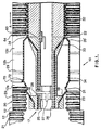
- the illustrated apparatus includes a travelling mold 10 advancing in the direction of arrow A.
- the mold consists of two sets of mold blocks 12, circulating on respective paths as described, for example, in Canadian Patent No. 1,083,766.
- This type of mold is not essential, however, and other embodiments of the invention may employ other forms of travelling mold tunnel.
- the mold 10 is associated with an extrusion die having an elongate nozzle 17 with an upstream annular orifice 16 for extruding a first, outer parison 18 into the mold cavity 20 of the mold which comprises a corrugated mold cavity 21 and a belled mold cavity 34.
- the nozzle 17 has an additional downstream orifice 22 for extruding a second inner parison 24 into the outer tube molded from the first parison.
- the die is also provided with a central core pipe 26.
- Pressurized air may be supplied through a pipe 27 running along the core pipe 26 and radial passages 28 inside the outer tube 18 upstream of the downstream die orifice 22. This pressurized air serves to blow mold the outer tube into the mold cavity 20 to mold it in crests 23 and troughs 31 in mold cavity 21 and into the shape of a bell in mold cavity 34.
- the core pipe 26 Downstream of orifice 22, the core pipe 26 carries a cooling plug 32 having a cooled outer surface.
- the cooling plug 32 presses the inner parison 24 against the corrugated outer parison 18 to fuse the tubes into a double walled pipe with a corrugated outer wall and a smooth inner wall in the mold cavity 21.
- the mold blocks 12a, 12b and 12c are shaped to form the outer wall into the cavity 34
- the outer parison 18 is molded into this bell section by blow molding, utilizing pneumatic pressure through radial passages 28 from pipe 27 within core pipe 26 by means of a spider 25.
- vacuum molding may be applied through passages 29 in mold blocks 12.
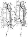
- a number of small diameter passages 70 are provided around the circumference of the mold to apply differential pressure between the interior and the exterior of outer tube wall 18 at a point where it is still soft or where it is heated to soften it. Suction may be applied through passages 70 to form small protruding balloons 72 of parison 18 into each passage 70. These are ruptured to release pressure from within outer tube wall 18. (see Figure 3).
- the actual orifice 71 may be located at the surface of outer tube wall 18 so as to concentrate suction over an area of parison equivalent to the area of the orifice 71.
- Protruding balloons 72 are ruptured either solely by differential pressure between the inside of bell section 34 and the outside of bell suction 34, or the rupture is aided by the presence of a sharp projection 80 within channel 70.
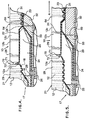
- a projection may be a needle or knife (see, for example, Figure 4).
- the use of an aid such as the needle or knife 80 may be only possible when the protruding balloon 72 is drawn into channel 70 under suction. If it is forced into bell section 34, it may be necessary to rupture it using air pressure alone,
- Inner parison wall 24 may be biased against the troughs 21 by means of the supply of pressurized air to the interior of inner tube wall 24 through radial passage 60.
- Passage 60 may be located just downstream of downstream orifice 22 so that it acts on inner parison 24 while it is still soft and is able to bond with the troughs 31 of outer tube wall formed from parison 18.
- Radial passages 60 may be formed by a small gap between cooling plug 32 and nose cone 33 therefor.
- This small gap 60 between the cooling plug 32 and the nose cone may be very small, say for example the gap may be around 10 thousandths of an inch.
- Figure 2 shows inner wall 24 biased against troughs 31 by pneumatic pressure from passage 60. There may be little or no tendency for the inner wall 24 to enter the corrugations due to air entrapped therein.
- Figures 3 and 4 show an enlarged detail of the wall of the parison being ballooned into the channels 70.
- the area of the ballooning is confined by the mouth or orifice 71 of each channel 70 and, thus, the protruding balloon may be shaped as a finger or cylinder.
- the balloon is shown rupturing under gas pressure alone but, as shown in Figure 4, the projection 80 is provided to aid the rupture.
- pressure may be used instead of suction so that the protrusion is in the opposite direction.
- the area of the parison wall which ballooned will be confined by the mouth or orifice 71 or, the protrusion itself may not be so finger shaped but may be more generally bulbous.
- projection 80 or other sharp, pointed instrument may serve to control the size of the eventual rupture. This may be important, since the size of rupture should only be sufficient to allow the escape of gas from bell section 34 but should not be big enough to affect the strength of the tube or, indeed, affect its physical properties or aesthetic appearance detrimentally.
- Figure 5 shows the mold tunnel advanced in the direction of arrow A so that the central part of belled section 34 is generally coincident with nozzle orifice 22 for inner all 24.
- the inner wall parison 24 may be seen pushed into mold cavity 34 to be against outer tube wall formed from parison 18.
- the inner tube wall is still soft and laminates with the outer wall to form a cuff or coupling part of the eventual tube (see Figure 8). Gas from within mold cavity 34 escapes through ruptured balloons 72 of the outer wall formed from parison 18.
- Figure 6 shows the mold tunnel even further advanced so that the inner wall has closed balloons 72 from the inside and no further gas escape therethrough is possible.
- Inner parison 24 will, as the next corrugated section advances, lose its tendency to confirm to the mold surface and will bond with the trough 31 of the corrugations.
- Figure 7 shows a modified mold cavity 34 having mold surfaces to enhance features of the eventual coupling or cuff of tube to be formed.
- the mold cavity 34 of Figure 7 includes an outwardly flared portion 82 which forms an enlarged mouth 83 in the eventual coupling (see Figure 8).
- bracketed pipe portion Y forms a female coupling part at one end of a pipe
- bracketed pipe portion Z forms a male coupling part for insertion into the female part as shown in Figure 8.
- the enlarged mouth 83 due to flared portion 82 may facilitate entry of part Z into part Y.
- An internal seating 85 for a seating O-ring may be provided by means of a groove 84 around the circumference of mold cavity 34.
- a suitable O-ring seated in the resulting seating will extend around the part Z when inserted to seal it with part Y.
- Means to prevent too easy separation of the assembled coupling may be provided by inwardly directed profiling of the mold cavity 34 to form an internally directed annular hook 87 of the resulting coupling. Hook 87 will extend inwardly and engage a crest 23 of the part Z as shown in Figure 8.
- the actual thickness of the coupling part Y may be influenced by speeding up or slowing down the speed of the travelling mold tunnel while mold cavity 34 is passing orifices 16 and 22. Thus a coupling of considerable strength and thickness may be produced.
- the inner wall extends smoothly within the cuter wall and only contacts the outer corrugated wall at the troughs 31.
- Such punctures may be very small indeed and at least probably, smaller than the ruptures of balloons 72.
Landscapes
- Engineering & Computer Science (AREA)
- Mechanical Engineering (AREA)
- Manufacturing & Machinery (AREA)
- Blow-Moulding Or Thermoforming Of Plastics Or The Like (AREA)
- Extrusion Moulding Of Plastics Or The Like (AREA)
Abstract
Claims (16)
- Procédé pour fabriquer un tuyau en matière plastique à paroi double à partir d'une extrudeuse comportant une buse (17) possédant un premier orifice (16) et un orifice (22) en aval du premier orifice dans un tunnel de moule mobile possédant une première région (21) pourvue d'une surface de moule cannelée et une seconde région (34) comportant une surface de moule en forme de cloche, la seconde région possédant également des ouvertures de paroi de moule (70) qui la traversent, ledit procédé consistant à extruder une première paraison (18) formée d'une matière thermoplastique fondue à partir du premier orifice, dans le tunnel de moule; mettre en forme la première paraison contre la surface de moule cannelée de manière à former alternativement des crêtes et des creux (23,31) et contre la surface de moule en cloche de manière à former une cloche dans la première paraison lors de la formation de parties de tuyau respectivement cannelée et à manchon, et étant caractérisé en ce qu'on soumet la première paraison à une pression différentielle au moyen desdites ouvertures formées dans la paroi du moule de manière à former des ballonnets (72) dans ladite première paraison, que l'on rompt les ballonnets pour produire des passages d'échappement d'air dans la cloche de la première paraison, qu'on extrude une seconde paraison (29) formée d'une matière thermoplastique fondue à partir du second orifice à l'intérieur du tunnel du moule, qu'on refoule à force la seconde paraison de manière qu'elle s'applique contre et forme un stratifié solide avec les cavités et la cloche sur la première paraison et qu'on refoule l'air entre la seconde paraison et la cloche de la première paraison hors du tuyau par les passages d'échappement d'air situés dans la première paraison.
- Procédé selon la revendication 1, selon lequel les ballonnets (72) sont formés à l'intérieur des ouvertures de paroi de moule situées dans la seconde région du tunnel du moule.
- Procédé selon la revendication 1, selon lequel les ballonnets sont formés à l'intérieur de la buse en étant repoussés vers l'intérieur à partir de la surface de moule en forme de cloche.
- Procédé selon la revendication 2, selon lequel les ballonnets sont formés par une pression d'air positive à l'intérieur du tunnel du moule.
- Procédé selon la revendication 2, selon lequel les ballonnets sont formés par aspiration à travers les ouvertures de la paroi du moule dans la seconde région.
- Procédé selon la revendication 4, selon lequel l'aspiration à travers les ouvertures de la paroi du moule dans la seconde région du tunnel du moule est suffisante pour rompre la première paraison sans rompre la seconde paraison.
- Procédé selon la revendication 1, selon lequel la première paraison est rompue par déplacement de la première paraison sur un outil de perçage (80) prévu dans chaque ouverture de la paroi de moule.
- Procédé selon la revendication 7, selon lequel la seconde paraison est repoussée contre la cloche dans la première paraison au moyen d'une pression pneumatique et contre les creux situés dans la première paraison au moyen de la combinaison d'une pression pneumatique et d'une pression mécanique.
- Dispositif pour fabriquer un tuyau en matière plastique à paroi double, ledit dispositif comprenant une extrudeuse possédant une buse (17) pourvue d'un premier orifice (16) et d'un second orifice (22) en aval du premier orifice, la buse délivrant des première et seconde paraisons (18,24) de la matière thermoplastique respectivement à travers les premier et second orifices pour former des parois extérieure et intérieure du tuyau à l'intérieur d'un tunnel de moule mobile possédant une première région (21) pourvue d'une surface de moule cannelée, et une seconde région (34) possédant une surface de moule en forme de cloche pour former respectivement une partie de tuyau cannelée et une partie de tuyau à manchon, le dispositif étant caractérisé en ce que la surface du moule en forme de cloche comporte des ouvertures (70) de la paroi de moule à travers lesquelles les ouvertures d'échappement sont formées dans la paroi extérieure de la partie de tuyau retroussée, ledit dispositif comprenant des moyens pour repousser la première paraison contre et former des crêtes et des creux alternés (23,31) sur la surface de moule cannelée et des moyens appliquant une pression différentielle pour repousser la première paraison contre et former une cloche sur la surface du moule en forme de cloche et former des ballonnets (72) dans la première paraison au niveau des ouvertures de la paroi, des moyens pour rompre les ballonnets pour former les ouvertures d'échappement d'air et des moyens pour repousser la seconde paraison contre et former un stratifié solide avec les creux de la première paraison et avec la cloche de la première paraison, à l'endroit situé entre les première et seconde paraisons est libéré par les ouvertures d'échappement d'air situées dans la première paraison et hors du dispositif par les ouvertures de la paroi de moule de la surface du moule en forme de cloche.
- Dispositif selon la revendication 9, dans lequel la première région du tunnel du moule comporte en outre une surface de moule (85) formant un renfoncement et une surface de moule (87) formant un crochet.
- Dispositif selon la revendication 9, dans lequel lesdits moyens servant à repousser la première paraison contre la surface de moule cannelée et la surface de moule en forme de cloche comprennent une pression pneumatique.
- Dispositif selon la revendication 9, dans lequel une combinaison d'une pression pneumatique et mécanique (32) est utilisée pour repousser à force la seconde paraison contre les creux de la première paraison, et dans lequel seule une pression pneumatique est utilisée pour repousser à force la seconde paraison contre la cloche de la première paraison.
- Dispositif selon la revendication 11, dans lequel la pression pneumatique est suffisante pour rompre la première paraison au niveau des ouvertures de la paroi du moule dans la seconde région du tunnel du moule sans rompre la seconde paraison.
- Dispositif selon la revendication 9, dans lequel les ouvertures de la paroi du moule sont prévues dans une partie amont de la seconde région du tunnel du moule.
- Dispositif selon la revendication 9, dans lequel un dispositif de perçage (80) est prévu dans chaque ouverture de la paroi du moule pour rompre les ballonnets.
- Dispositif selon la revendication 9, comprenant des moyens pour perforer les crêtes dans la première paraison pour libérer l'air piégé entre les première et seconde paraisons dans les crêtes.
Applications Claiming Priority (1)
| Application Number | Priority Date | Filing Date | Title |
|---|---|---|---|
| PCT/CA1993/000260 WO1995001251A1 (fr) | 1993-06-30 | 1993-06-30 | Procede et appareil permettant de former un tuyau thermoplastique a double paroi a emboitements integres |
Publications (2)
| Publication Number | Publication Date |
|---|---|
| EP0708702A1 EP0708702A1 (fr) | 1996-05-01 |
| EP0708702B1 true EP0708702B1 (fr) | 2000-06-14 |
Family
ID=4172977
Family Applications (1)
| Application Number | Title | Priority Date | Filing Date |
|---|---|---|---|
| EP93914573A Expired - Lifetime EP0708702B1 (fr) | 1993-06-30 | 1993-06-30 | Procede et appareil permettant de former un tuyau thermoplastique a double paroi a emboitements integres |
Country Status (5)
| Country | Link |
|---|---|
| EP (1) | EP0708702B1 (fr) |
| JP (1) | JP3210673B2 (fr) |
| DE (1) | DE69328879T2 (fr) |
| ES (1) | ES2149209T3 (fr) |
| WO (1) | WO1995001251A1 (fr) |
Families Citing this family (14)
| Publication number | Priority date | Publication date | Assignee | Title |
|---|---|---|---|---|
| EP0781642B1 (fr) * | 1995-12-27 | 2003-04-23 | Uponor Innovation Ab | Procédé et appareil pour la production de tubes en matière plastique, et un tube plastique |
| DE19724113A1 (de) * | 1997-06-09 | 1998-12-10 | Ralph Peter Dr Hegler | Verbundrohr mit angeformter Rohr-Muffe und Verfahren zu dessen Herstellung |
| DE29813235U1 (de) | 1998-03-09 | 1998-12-03 | Lupke, Manfred Arno Alfred, Concord, Ontario | Vorrichtung zum Formen von Kunststoffrohren |
| EP1379377B1 (fr) * | 2000-09-11 | 2011-02-02 | Manfred Arno Alfred Lupke | Appareil de moulage dote d'un tunnel de moulage a mouvement alternatif et capable de produire differentes formes d'articles |
| DE10110064B4 (de) * | 2001-03-02 | 2005-03-31 | Lupke, Manfred Arno Alfred, Thornhill | Verfahren und Vorrichtung zur Herstellung eines doppelwandigen thermoplastischen Rohres mit einer Rohrmuffe |
| DE10165124B3 (de) | 2001-03-02 | 2018-05-30 | Manfred Arno Alfred Lupke | Verfahren und Vorrichtung zur Herstellung eines doppelwandigen thermoplastischen Rohres mit einer Rohrmuffe |
| PT1363766E (pt) * | 2001-03-02 | 2007-10-22 | Manfred Arno Alfred Lupke | Processo e dispositivo para o fabrico de um tubo termoplástico de parede dupla com uma luva de ligação de tubo |
| JP3883859B2 (ja) * | 2001-12-12 | 2007-02-21 | 三桜工業株式会社 | 蛇腹チューブ製造方法および装置 |
| DE10335518A1 (de) | 2003-07-31 | 2005-02-24 | Manfred Arno Alfred Thornhill Lupke | Vorrichtung zur Herstellung eines doppelwandigen thermoplastischen Rohrs mit einer Rohrmuffe |
| CA2450560C (fr) * | 2003-11-24 | 2006-05-16 | Manfred A. A. Lupke | Systeme de moulage de tuyaux avec commandes de depression et de temperature pour les bouchons de refroidissement |
| ES2290594T3 (es) * | 2004-07-03 | 2008-02-16 | Ralph-Peter Dr.-Ing. Hegler | Procedimiento para la fabricacion continua de un tubo corrugado de doble pared con una manguera, el tubo corrugado de doble pared y el aparato para llevar a cabo el procedimiento. |
| DE102007050923A1 (de) | 2007-10-23 | 2009-05-07 | Unicor Gmbh | Verfahren und Vorrichtung zur Herstellung eines doppelwandigen thermoplastischen Wellrohres mit einer Rohrmuffe |
| DE102010043786B4 (de) * | 2010-11-11 | 2013-07-18 | Ralph Peter Hegler | Vorrichtung zur Herstellung von Rohren aus thermoplastischem Kunststoff |
| CN108274722B (zh) * | 2018-03-26 | 2023-11-21 | 大连三垒科技有限公司 | 波纹管双层承插口在线成型扩口模块尾部压紧装置 |
Family Cites Families (12)
| Publication number | Priority date | Publication date | Assignee | Title |
|---|---|---|---|---|
| FR70398E (fr) * | 1974-03-22 | 1959-04-06 | Electronique & Physique | Perfectionnements aux dispositifs de prise de vues de télévision et cinématographie |
| CA1083766A (fr) | 1977-02-07 | 1980-08-19 | Gerd P.H. Lupke | Appareil servant a la fabrication de tubes thermoplastiques |
| CA1172813A (fr) | 1982-06-16 | 1984-08-21 | Lupke, Manfred A. A. | Dispositif pour la production de tubes multiparoi en matiere thermoplastique |
| CA1187258A (fr) * | 1982-12-02 | 1985-05-21 | Lupke, Manfred A. A. | Methode et dispositif de fabrication de tubes thermoplastiques a double paroi et emboitement |
| US4500284A (en) | 1983-09-16 | 1985-02-19 | Lupke Manfred Arno Alfred | Forming single wall bells in double wall pipe |
| JPS6062930U (ja) * | 1983-10-05 | 1985-05-02 | タキロン株式会社 | 二重壁管 |
| US4846660A (en) * | 1984-07-18 | 1989-07-11 | Contech Construction Products Inc. | Apparatus for producing double wall pipe |
| JPS61148036A (ja) * | 1984-12-21 | 1986-07-05 | Takiron Co Ltd | 二重壁管の製造法 |
| DE3701822A1 (de) * | 1987-01-22 | 1988-08-11 | Uponor Nv | Verfahren und anordnung zum strangpressen von kunststoffrohren |
| JPH066329B2 (ja) * | 1987-02-05 | 1994-01-26 | ウポノール・エヌ・ベー | プラスチツク管の押出しのための方法及び装置 |
| CA1329871C (fr) * | 1989-05-17 | 1994-05-31 | Manfred A. A. Lupke | Faconnage de tubes au moyen d'un poincon refroidisseur utilisant la pression d'aspiration et la pression d'air comprime |
| DE4210482A1 (de) * | 1992-03-31 | 1993-10-07 | Wilhelm Hegler | Verfahren und Vorrichtung zur fortlaufenden Herstellung eines Verbundrohres mit Rohr-Muffe |
-
1993
- 1993-06-30 DE DE69328879T patent/DE69328879T2/de not_active Expired - Lifetime
- 1993-06-30 ES ES93914573T patent/ES2149209T3/es not_active Expired - Lifetime
- 1993-06-30 JP JP50317895A patent/JP3210673B2/ja not_active Expired - Lifetime
- 1993-06-30 WO PCT/CA1993/000260 patent/WO1995001251A1/fr not_active Ceased
- 1993-06-30 EP EP93914573A patent/EP0708702B1/fr not_active Expired - Lifetime
Also Published As
| Publication number | Publication date |
|---|---|
| JP3210673B2 (ja) | 2001-09-17 |
| ES2149209T3 (es) | 2000-11-01 |
| DE69328879T2 (de) | 2000-11-09 |
| DE69328879D1 (de) | 2000-07-20 |
| JPH09503455A (ja) | 1997-04-08 |
| WO1995001251A1 (fr) | 1995-01-12 |
| EP0708702A1 (fr) | 1996-05-01 |
Similar Documents
| Publication | Publication Date | Title |
|---|---|---|
| CA2072663C (fr) | Methode et machine pour former des tubes thermoplastiques a double paroi et tulipes integrees | |
| US4500284A (en) | Forming single wall bells in double wall pipe | |
| EP0708702A1 (fr) | Procede et appareil permettant de former un tuyau thermoplastique a double paroi a emboitements integres | |
| US4865797A (en) | Method and an apparatus for the extrusion of plastic pipes | |
| US6458311B1 (en) | Method for the continuous manufacture of a twin-wall pipe having a pipe socket | |
| IE40874B1 (en) | A method of and apparatus for extruding tubes | |
| JP3015357B2 (ja) | 多区分プラスチック容器及びその製造方法 | |
| HUT48517A (en) | Method and apparatus for producing ribbed tubes | |
| JP2008504154A (ja) | ソケット付き二重壁管を連続的に製造する方法と、二重壁管と、その方法を実施し、その二重壁管を製造するための装置 | |
| US5429398A (en) | Coupling for ribbed pipe | |
| KR100275033B1 (ko) | 다층용기의 제조방법 및 그 장치 | |
| EP0483153B1 (fr) | Procede de formage de tubes par l'application d'aspiration et de pression pneumatique a la surface du mandrin de refroidissement | |
| US4522854A (en) | Integral film tear strip | |
| CA1328155C (fr) | Methode de moulage par soufflage permettant de fabriquer des contenants plats a parois d'epaisseurs tres variables | |
| EP1468808A4 (fr) | Procede de production d'un tube ondule a double paroi | |
| JPH066329B2 (ja) | プラスチツク管の押出しのための方法及び装置 | |
| EP0368302A3 (fr) | Procédé et dispositif pour la production de feuilles en mousse de polyoléfine | |
| EP1379377B1 (fr) | Appareil de moulage dote d'un tunnel de moulage a mouvement alternatif et capable de produire differentes formes d'articles | |
| JP2606262Y2 (ja) | 薄肉チューブ成形装置 | |
| GB1207448A (en) | Extrusion apparatus for the production of tubes and tubular films of synthetic organic thermoplastic polymeric material | |
| CA1281523C (fr) | Methode et dispositif d'extrusion de canalisations en matiere plastique | |
| JP3065128B2 (ja) | ブロー成形方法 | |
| CA2182132A1 (fr) | Methode de moulage de tuyaux en plastique ondule, a double paroi et a joints integres | |
| JPS55146716A (en) | Production of side braid for automobile | |
| JPS588334B2 (ja) | ブブンテキアツニクブオユウスル ゴウセイジユシカンノセイゾウソウチ |
Legal Events
| Date | Code | Title | Description |
|---|---|---|---|
| PUAI | Public reference made under article 153(3) epc to a published international application that has entered the european phase |
Free format text: ORIGINAL CODE: 0009012 |
|
| 17P | Request for examination filed |
Effective date: 19960118 |
|
| AK | Designated contracting states |
Kind code of ref document: A1 Designated state(s): DE ES FR GB IT |
|
| RBV | Designated contracting states (corrected) |
Designated state(s): AT BE CH DE DK ES FR GB GR IE IT LI LU MC NL PT SE |
|
| 17Q | First examination report despatched |
Effective date: 19980422 |
|
| GRAG | Despatch of communication of intention to grant |
Free format text: ORIGINAL CODE: EPIDOS AGRA |
|
| GRAG | Despatch of communication of intention to grant |
Free format text: ORIGINAL CODE: EPIDOS AGRA |
|
| GRAH | Despatch of communication of intention to grant a patent |
Free format text: ORIGINAL CODE: EPIDOS IGRA |
|
| GRAH | Despatch of communication of intention to grant a patent |
Free format text: ORIGINAL CODE: EPIDOS IGRA |
|
| GRAH | Despatch of communication of intention to grant a patent |
Free format text: ORIGINAL CODE: EPIDOS IGRA |
|
| ITF | It: translation for a ep patent filed | ||
| GRAH | Despatch of communication of intention to grant a patent |
Free format text: ORIGINAL CODE: EPIDOS IGRA |
|
| GRAA | (expected) grant |
Free format text: ORIGINAL CODE: 0009210 |
|
| AK | Designated contracting states |
Kind code of ref document: B1 Designated state(s): DE ES FR GB IT |
|
| RBV | Designated contracting states (corrected) |
Designated state(s): DE ES FR GB IT |
|
| PGFP | Annual fee paid to national office [announced via postgrant information from national office to epo] |
Ref country code: FR Payment date: 20000623 Year of fee payment: 8 |
|
| PGFP | Annual fee paid to national office [announced via postgrant information from national office to epo] |
Ref country code: ES Payment date: 20000626 Year of fee payment: 8 |
|
| REF | Corresponds to: |
Ref document number: 69328879 Country of ref document: DE Date of ref document: 20000720 |
|
| ET | Fr: translation filed | ||
| REG | Reference to a national code |
Ref country code: IE Ref legal event code: FG4D |
|
| REG | Reference to a national code |
Ref country code: ES Ref legal event code: FG2A Ref document number: 2149209 Country of ref document: ES Kind code of ref document: T3 |
|
| REG | Reference to a national code |
Ref country code: IE Ref legal event code: MM4A |
|
| PLBE | No opposition filed within time limit |
Free format text: ORIGINAL CODE: 0009261 |
|
| STAA | Information on the status of an ep patent application or granted ep patent |
Free format text: STATUS: NO OPPOSITION FILED WITHIN TIME LIMIT |
|
| 26N | No opposition filed | ||
| PG25 | Lapsed in a contracting state [announced via postgrant information from national office to epo] |
Ref country code: ES Free format text: LAPSE BECAUSE OF NON-PAYMENT OF DUE FEES Effective date: 20010701 |
|
| REG | Reference to a national code |
Ref country code: GB Ref legal event code: IF02 |
|
| PG25 | Lapsed in a contracting state [announced via postgrant information from national office to epo] |
Ref country code: FR Free format text: LAPSE BECAUSE OF NON-PAYMENT OF DUE FEES Effective date: 20020228 |
|
| REG | Reference to a national code |
Ref country code: ES Ref legal event code: FD2A Effective date: 20020711 |
|
| PGFP | Annual fee paid to national office [announced via postgrant information from national office to epo] |
Ref country code: GB Payment date: 20110628 Year of fee payment: 19 |
|
| PGFP | Annual fee paid to national office [announced via postgrant information from national office to epo] |
Ref country code: IT Payment date: 20110627 Year of fee payment: 19 |
|
| PGFP | Annual fee paid to national office [announced via postgrant information from national office to epo] |
Ref country code: DE Payment date: 20120627 Year of fee payment: 20 |
|
| GBPC | Gb: european patent ceased through non-payment of renewal fee |
Effective date: 20120630 |
|
| PG25 | Lapsed in a contracting state [announced via postgrant information from national office to epo] |
Ref country code: IT Free format text: LAPSE BECAUSE OF NON-PAYMENT OF DUE FEES Effective date: 20120630 |
|
| PG25 | Lapsed in a contracting state [announced via postgrant information from national office to epo] |
Ref country code: GB Free format text: LAPSE BECAUSE OF NON-PAYMENT OF DUE FEES Effective date: 20120630 |
|
| REG | Reference to a national code |
Ref country code: DE Ref legal event code: R071 Ref document number: 69328879 Country of ref document: DE |
|
| PG25 | Lapsed in a contracting state [announced via postgrant information from national office to epo] |
Ref country code: DE Free format text: LAPSE BECAUSE OF EXPIRATION OF PROTECTION Effective date: 20130702 |