EP0708726B1 - Mini-manches actifs relies mecaniquement - Google Patents
Mini-manches actifs relies mecaniquement Download PDFInfo
- Publication number
- EP0708726B1 EP0708726B1 EP94923545A EP94923545A EP0708726B1 EP 0708726 B1 EP0708726 B1 EP 0708726B1 EP 94923545 A EP94923545 A EP 94923545A EP 94923545 A EP94923545 A EP 94923545A EP 0708726 B1 EP0708726 B1 EP 0708726B1
- Authority
- EP
- European Patent Office
- Prior art keywords
- control
- handles
- active
- movement
- handle
- Prior art date
- Legal status (The legal status is an assumption and is not a legal conclusion. Google has not performed a legal analysis and makes no representation as to the accuracy of the status listed.)
- Expired - Lifetime
Links
Images




Classifications
-
- B—PERFORMING OPERATIONS; TRANSPORTING
- B64—AIRCRAFT; AVIATION; COSMONAUTICS
- B64C—AEROPLANES; HELICOPTERS
- B64C13/00—Control systems or transmitting systems for actuating flying-control surfaces, lift-increasing flaps, air brakes, or spoilers
- B64C13/02—Initiating means
- B64C13/04—Initiating means actuated personally
- B64C13/12—Dual control apparatus
-
- B—PERFORMING OPERATIONS; TRANSPORTING
- B64—AIRCRAFT; AVIATION; COSMONAUTICS
- B64C—AEROPLANES; HELICOPTERS
- B64C13/00—Control systems or transmitting systems for actuating flying-control surfaces, lift-increasing flaps, air brakes, or spoilers
- B64C13/02—Initiating means
- B64C13/04—Initiating means actuated personally
- B64C13/042—Initiating means actuated personally operated by hand
- B64C13/0421—Initiating means actuated personally operated by hand control sticks for primary flight controls
-
- B—PERFORMING OPERATIONS; TRANSPORTING
- B64—AIRCRAFT; AVIATION; COSMONAUTICS
- B64C—AEROPLANES; HELICOPTERS
- B64C13/00—Control systems or transmitting systems for actuating flying-control surfaces, lift-increasing flaps, air brakes, or spoilers
- B64C13/02—Initiating means
- B64C13/04—Initiating means actuated personally
- B64C13/10—Initiating means actuated personally comprising warning devices
-
- B—PERFORMING OPERATIONS; TRANSPORTING
- B64—AIRCRAFT; AVIATION; COSMONAUTICS
- B64C—AEROPLANES; HELICOPTERS
- B64C13/00—Control systems or transmitting systems for actuating flying-control surfaces, lift-increasing flaps, air brakes, or spoilers
- B64C13/24—Transmitting means
- B64C13/26—Transmitting means without power amplification or where power amplification is irrelevant
- B64C13/28—Transmitting means without power amplification or where power amplification is irrelevant mechanical
- B64C13/30—Transmitting means without power amplification or where power amplification is irrelevant mechanical using cable, chain, or rod mechanisms
-
- B—PERFORMING OPERATIONS; TRANSPORTING
- B64—AIRCRAFT; AVIATION; COSMONAUTICS
- B64C—AEROPLANES; HELICOPTERS
- B64C13/00—Control systems or transmitting systems for actuating flying-control surfaces, lift-increasing flaps, air brakes, or spoilers
- B64C13/24—Transmitting means
- B64C13/38—Transmitting means with power amplification
- B64C13/50—Transmitting means with power amplification using electrical energy
- B64C13/503—Fly-by-Wire
-
- B—PERFORMING OPERATIONS; TRANSPORTING
- B64—AIRCRAFT; AVIATION; COSMONAUTICS
- B64C—AEROPLANES; HELICOPTERS
- B64C13/00—Control systems or transmitting systems for actuating flying-control surfaces, lift-increasing flaps, air brakes, or spoilers
- B64C13/24—Transmitting means
- B64C13/38—Transmitting means with power amplification
- B64C13/50—Transmitting means with power amplification using electrical energy
- B64C13/505—Transmitting means with power amplification using electrical energy having duplication or stand-by provisions
-
- G—PHYSICS
- G05—CONTROLLING; REGULATING
- G05G—CONTROL DEVICES OR SYSTEMS INSOFAR AS CHARACTERISED BY MECHANICAL FEATURES ONLY
- G05G9/00—Manually-actuated control mechanisms provided with one single controlling member co-operating with two or more controlled members, e.g. selectively, simultaneously
- G05G9/02—Manually-actuated control mechanisms provided with one single controlling member co-operating with two or more controlled members, e.g. selectively, simultaneously the controlling member being movable in different independent ways, movement in each individual way actuating one controlled member only
- G05G9/04—Manually-actuated control mechanisms provided with one single controlling member co-operating with two or more controlled members, e.g. selectively, simultaneously the controlling member being movable in different independent ways, movement in each individual way actuating one controlled member only in which movement in two or more ways can occur simultaneously
- G05G9/047—Manually-actuated control mechanisms provided with one single controlling member co-operating with two or more controlled members, e.g. selectively, simultaneously the controlling member being movable in different independent ways, movement in each individual way actuating one controlled member only in which movement in two or more ways can occur simultaneously the controlling member being movable by hand about orthogonal axes, e.g. joysticks
- G05G2009/04766—Manually-actuated control mechanisms provided with one single controlling member co-operating with two or more controlled members, e.g. selectively, simultaneously the controlling member being movable in different independent ways, movement in each individual way actuating one controlled member only in which movement in two or more ways can occur simultaneously the controlling member being movable by hand about orthogonal axes, e.g. joysticks providing feel, e.g. indexing means, means to create counterforce
-
- Y—GENERAL TAGGING OF NEW TECHNOLOGICAL DEVELOPMENTS; GENERAL TAGGING OF CROSS-SECTIONAL TECHNOLOGIES SPANNING OVER SEVERAL SECTIONS OF THE IPC; TECHNICAL SUBJECTS COVERED BY FORMER USPC CROSS-REFERENCE ART COLLECTIONS [XRACs] AND DIGESTS
- Y02—TECHNOLOGIES OR APPLICATIONS FOR MITIGATION OR ADAPTATION AGAINST CLIMATE CHANGE
- Y02T—CLIMATE CHANGE MITIGATION TECHNOLOGIES RELATED TO TRANSPORTATION
- Y02T50/00—Aeronautics or air transport
- Y02T50/40—Weight reduction
Definitions
- This invention relates to the use of active sidestick hand controllers as replacements for columns employed in conventional column controlled flight control systems. More specifically, the invention relates to the use of the active sidesticks as an improved replacement for convention column controls, or alternatively, for use in a fly-by-wire system with a backup mechanical linkage between the sidestick and the flight control system in the event of failure of the fly-by-wire system.
- Each column includes handgrips on what can be termed a steering wheel.
- the columns are pivotable along one axis to control pitch of an aircraft and the steering wheel serves to control roll of the aircraft.
- the two columns are mechanically cross-linked and are connected to parallel mechanical systems (one for port side and one for starboard side) which control the aircraft flight control surfaces.
- each system consists of cables connected by means of pulleys to the aircraft systems (e.g. mechanical, electrical or hydraulic) which in turn control the flight control surfaces in a manner corresponding to movement of the column or the steering wheel thereof.
- the two columns which are mechanically cross-linked can be disconnected by means of a selective connection mechanism.
- a disadvantage in these types of systems is that they are often bulky, require significantly more space in an aircraft cockpit and involve addition of servo and trim motors connected to the cable system for autopilot backdrive and trim. Thus, it becomes desirable to replace such systems with active sidesticks, including servomotors, which are smaller and easier to use in controlling an aircraft then conventional column control systems.
- EP 384806 describes an active hand controller system for aircraft.
- an active hand controller system comprising first and second active control handles each moveable about a pitch axis and a roll axis and each including sensor means comprising means for detecting movement of the respective first and second active control handles about said axes and for generating a signal representative of said movement.
- Control electronic means receive said signal from the sensor means and generate a control signal in response thereto representative of said movement.
- a servo motor is connected on each axis to each of the first and second active control handles. Said control signal is communicated to the control electronic means of the first and second control handle unactuated by the user such that the servo motors of the unactuated first and second control handle cause movement of the unactuated control handle in concert with the control handle actuated by the user.
- the present invention provides an active hand controller system for aircraft as defined in Claim 1 hereinafter.
- the present invention may include any one or more of the features set out in dependent Claims 2 to 5 hereinafter.
- Control electronics of the type disclosed in U.S. Patent No. 5,291,113 may serve to receive the signals from the sensors for generating a control signal in response thereto for controlling at least one servo motor per axis connected to the manual control stick.
- the servo motor is connected to the manual control stick and to cable linkages of the type in use in conventional column control systems, which are connected to an aircraft's mechanical, electrical or hydraulic flight control system.
- the servo motor when controlling the axis in response to the control electronics will also control the cable linkages which are connected to the aircraft flight control system.
- the system of the invention may include two manual control sticks arranged in a dual cockpit configuration and having a cross feed of signals to also have the control electronics provide a signal from one control stick and cable linkages to the other to cause the other control stick and cable linkages to move in a manner duplicative of the manner in which the first control stick is moved.
- an active hand controller for a fly-by-wire flight control system of an aircraft of the type disclosed in U.S. Patent No. 5,291,113.
- the manual control stick is electrically connected to the flight control system to provide a command signal from the control electronics as is disclosed in U.S. Patent No. 5,291,113.
- the cable system leading to the aircraft mechanical, electrical or hydraulic flight control system operates only as a backup with the control stick disengaged from the cable and linkages by means of a clutch which is in a disengaged condition when power is on, but which engages the cable system should there be a failure of the fly-by-wire system such that with or without the servo motors using the manual control stick, the pilot or copilot can maintain control of the aircraft.
- the motors are selected to be backdrivable with forces applied to the control stick (e.g., forces on the stick will cause motion) so as to not obstruct movement of the cables as a result of a pilot or copilot applying force to the handle of the control stick.
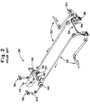
- the system for pitch control is generally designated by the numeral 10.
- Two columns 12 are arranged in a parallel arrangement and are pivotable in a manner shown by arrows A.
- the columns are interconnected by means of interconnect shaft 18 which includes a pitch mechanical disconnect which can serve to disconnect one column from the other by pulling handle 16.
- a conventional control column balance spring 20 stabilizes movement and use of the column 12.
- a link 22 to the forward quadrant pitch cable pulley assembly 24 connects the column 12 to cable 26, which in turn leads to and is connected to the aft quadrant 30 of the system 10.
- connection at the aft quadrant 30 leads to the mechanical, electrical or hydraulic system of the flight control system through load limiters 34 for control thereof Since the columns 12 are connected to the flight control system by means of cables 26, the "feel" of a mechanically linked system is not ordinarily maintained at the column for the users thereof. In order to ensure such "feel,” as shown by the dashed line, there is connected to the cables 26 a pitch feel simulator unit 32 of conventional construction, as shown in Fig. 1b.
- An autopilot servo 28 serves to provide movement to the column in a manner corresponding to control pitch of the aircraft by the autopilot when the autopilot is engaged.
- Fig. 2 further illustrates the roll control assembly 36 of the prior art column controlled system.
- the steering wheel 38 is connected to cables 12a and is shown connected by means of forward quadrant 44 to cable assembly 52 which serves to control roll as connected to port and starboard aileron controls of an aircraft.
- a roll disconnect mechanism 40 which enables the cables 12a to be disconnected from each other by merely pulling at handle 42 which then disconnects the two columns at the roll mechanical disconnect 46.
- Balance springs 50 are arranged in a conventional configuration to maintain balance between the parallel systems of cables 12a.
- the cables 52 lead to the aft quadrant (not numbered) and are connected in a conventional configuration to a trim mechanism 54, trim actuator 56, and as in the case with the pitch control system of Figs. 1a and 1b, there is provided an artificial feel unit 58 to provide artificial feel to the steering wheels 38.
- An autopilot servo 60 serves to provide movement to the wheel in a manner corresponding to control roll of the aircraft by the autopilot when the autopilot is engaged.
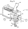
- Fig. 3 schematically illustrates in partial transparent and perspective view, a mechanically linked active sidestick 62 of the type employed in the present invention.
- the active sidestick 62 includes a handle 80 which is moveable about a pitch axis (x) and a roll axis (y).
- the handle 80 includes connected thereto at least one motor on each axis generally illustrated by the number 76a for the pitch axis and 76b for the roll axis. Although one motor is shown numbered for each axis, it will be appreciated that more than one can be employed, depending on the redundant configuration.
- a pitch interface link 68 Connected to motor 76a is a pitch interface link 68 which has connected thereto a push rod 70 which leads to the forward quadrant cable pulley in both embodiments of the present invention.
- a roll pulley assembly 72 Connected to the motor 76b, is a roll pulley assembly 72 including cable 74, also implemented in both embodiments of the present invention.
- the roll cable 74 and the push rod 70 are connected to the forward quadrant in a manner similar to that illustrated in Figs. 1a-2.
- a mother board 66 interconnects the control electronics 64 sensors connected (not shown) to handle 80 to detect movement and force thereof and generate a signal, typically a position signal, or even a force signal as a result of force applied to and movement of handle 80 caused by a user.
- the operation of the control electronics through the sensors as well as the motors 76a and 76b will not be detailed further herein but is as described in U.S. Patent No. 5,291,113.
- the control electronics serve to control the operation of the motors in response to a pilot's use of the handle 80 to cause the motor to drive the pitch and roll linkages and cables as well as to drive movement of the handle 80 in response to any external control signal being received by the electronics, which are then processed and transmitted to a respective motor 76a or 76b to move a respective handle 80.
- the motors 76a and 76b provide the "feel" to the system during piloted operation.
- a decouple mechanism can be implemented similar to that achieved on previous purely mechanically linked systems such as the commercially available military Cobra helicopter forward sidestick configuration. This decouple mechanism has been implemented in prior art and as such is not a subject matter of this invention.
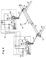
- FIG. 4 A first embodiment of a pitch control system in accordance with the invention is generally illustrated at Fig. 4.
- the pitch control system mechanically connected to the aircraft flight control system is essentially the same as illustrated in Fig. 1a without the mechanical interconnect shaft, and in addition, a disengage clutch 86 for pitch is configured so that the active sidesticks 62 are disengaged from the cables 26 when power is on.
- the system is employed in a fly-by-wire system wherein the aircraft flight control surfaces are controlled by electrical signals transmitted through lines 88 from the respective active sidesticks 62.
- Movement of the handles 80 results in position and force signals being transmitted and processed by control electronics 90 to be transmitted to the respective motor 76a, and such movement also results in a direct signal for control of the fly-by-wire system being transmitted through lines 88, depending on which handle is moved as is described in said above-referenced international applications and U.S. patent.
- a control signal being transmitted on its line 88, as well as a torque signal for electronic coupling being transmitted by means of switch 84 when closed, to the control electronics 90 of the copilot, i.e., right side, to result in a signal being fed to motor 76a to cause the handle 80 to move in a manner corresponding to that of the pilot handle 80 on the left side.
- a center command control line 92 for inputting a number of different signals, for example, for signals from an autopilot system and for signals in response to the flight control surfaces being forced to move by external forces. Such an applied signal results in a corresponding movement of both handles 80 caused by being driven by the respective motors 76a.
- a complete system shutdown may occur (e.g., power loss), in which case the clutches 86 will close allowing the handle 80 to be driven to drive the cables 26 to maintain control of the aircraft flight control system.
- the motors are backdrivable and as such will not impede movement of the handle 80 and cables 26.
- the handles 80 are moved based on pure physical strength of pilot and copilot alone resulting in degraded pilot "feel".
- An alternative failure can occur when there is a failure of the electronics of the fly-by-wire system, but power is maintained to motors 76a. In this scenario the motors 76a drive the cables in a manner where not much force is required of the pilot or copilot in moving the control stick handles 80.
- One alternative configuration of the embodiment of Fig. 4 can include a mechanical interconnecting cross-link similar to that of Fig. 1 a connecting the copilot and pilot active sidesticks 62 not only electrically by means of switch 84 but also mechanically with a shaft similar to interconnect shaft 18 also having a mechanical disconnect 14 for pitch as shown in Fig. 1a.
- the clutches 86 will allow engagement of the mechanical linkage flight control system as presented or independently engage or disengage the mechanical cross-link interconnecting shaft.
- Fig. 5 The roll control system of this embodiment of the invention is shown in Fig. 5 in a manner similar to that of Fig. 4. It will be appreciated that the control electronics is likewise similar to that disclosed in U.S. Patent No. 5,291,113, and need not be disclosed in greater detail herein with reference being made to said U.S. patent for the details of said electronics.
- a roll clutch 94 serves to disengage the mechanical system and cables 52 at the forward quadrant roll cable pulley assembly 44 from the active sidesticks 62.
- the active sidesticks are typically connected and interfaced to the forward quadrant pulley 44 through a roll output pulley 45.
- a control signal in the fly-by-wire mode is typically generated by movement of the handles 80 by the sensor thereof and transmitted through lines 96 to the fly-by-wire control system.
- the torque coupling signals are interconnected by means of a switch 98 which serve to transmit cross signals between active sidestick assemblies 62 to ensure that they track each other in movement by processing the cross signals in the respective control electronics 90, which are then transmitted to motors 76b to drive the handles 80.
- a center command or autopilot signal is also transmitted to the roll axis of the system by means of an input line 100 as illustrated in Fig. 5.
- first and second alternative variations of both mechanical and electrical interconnection between the pilot and copilot roll control systems will be effected in the same manner as discussed with reference to Fig. 4.
- a mechanical cross-link can be provided similar to that of roll interconnect shaft 48 of Fig. 2 in addition to the electrical interconnection.
- the connection through switch 98 between the torque coupling signals can be such that there is no connection resulting in only the mechanical interconnect shaft 48.
- Figs. 6 and 7 contemplates the use of the active sidestick 62 as a direct substitution for the conventional mechanical column 12 of Figs. 1a, 1b and 2.
- the sidesticks of 62 since the sidesticks of 62 of necessity employ motors 76a and 76b and electronics electrically cross-linking them, there will be some electronics involved similar to that disclosed in U.S. Patent No. 5,291,113, but there is no electrical connection to a fly-by-wire system as generally illustrated by lines 88 and 96 of Figs. 4 and 5.
- FIG. 6 and 7 Further simplification in the embodiments illustrated in Figs. 6 and 7 from Figs. 4 and 5, is that flight control is achieved through the cables 26 and 52 respectively connected to the aircraft mechanical, electrical or hydraulic flight control system.
- the clutches 86 and 94 of Figs. 4 and 5 for the fly-by-wire implementation are eliminated in the preferred configuration shown in Figs. 6 and 7 for pitch and roll control respectively for flight control with a mechanically linked sidestick.
- the systems illustrated in Figs. 6 and 7 have the advantage of the servo motors 76a and 76b driving the cables 26 and 52, wherein not much force is required of the pilot and copilot in moving the control stick handles 80.
- servo motors 76a and 76b are used to achieve the functions of Figs. 1a and 2 autopilot servo 28 and 60 with associated mechanisms and the Fig. 2 trim servo 56 with associated mechanisms, thereby simplifying the mechanical control system reducing complexity and weight.
- Fig. 6 generally illustrates the connection of the active sidesticks 62 in a manner similar to that of Fig. 1a and including an interconnect shaft 18 with a pitch mechanical disconnect mechanism 14 which is activated by handle 16.
- the system for pitch control is connected by means of cables 26 through forward quadrant pulley 24 which is in turn driven by the link 22 to the forward quadrant.
- the active sidestick 62 handle 80 may be driven to result in signals picked up by sensors and transmitted to control electronics 90.
- the control electronics 90 translates the signal into a motor control signal which is transmitted to motor 76a.
- the motor 76a drives the linkage 22.
- the motor 76a is selected to be of a type sufficiently powerful and effective to drive the linkage 22 to control the cables 26 which in turn drives the aircraft mechanical, electrical or hydraulic systems for control of the flight control surfaces.
- the active sidesticks 62 are also electronically interconnected through switch 84 such that, for example, when the left side pilot handle 80 is moved, a torque signal for electronic coupling is transmitted by means of switch 84 when closed to corresponding control electronics 90 of the copilot sidestick 62 to result in an augmented signal being transmitted from the control electronics 90 to motor 76a to drive handle 80 in a manner corresponding to the movement of the other handle 80.
- the electronic disconnect switch 84 for the electronic coupling can be simultaneously controlled by the disconnect handle 16 when mechanical cross-cockpit disconnect mechanism 14 is selected. The cross-cockpit tracking between the pilot and copilot sidesticks will be dominantly controlled by the electrical interconnection through switch 84 because of the inherent backlash and compliance in the mechanical interconnection via shaft 18 and associated mechanisms.
- the system can be configured to include an electrical input through line 92 from external sensors detecting the movement of flight control surfaces or, for example, from an autopilot system which would ensure that the handles 90 track the movement of the flight control surfaces or the commands of the autopilot system to the flight control surfaces.
- an alternative interconnect between the two active sidestick systems 62 from Figs. 6 and 7 can be achieved.
- the alternative from Figs. 6 and 7 may be configured such that only electrical signals are transmitted between sidesticks 62. With this alternative, the complete electrical interconnect can be maintained but the mechanical interconnect through shalt 18 can be eliminated.
- Fig. 7 illustrates the roll control system in a manner similar to that of Fig. 5 and Fig. 6.
- the active sidesticks 62 are interconnected electrically through switch 98 in a manner similar to that of Fig. 6.
- the roll control mechanical interface is via the roll control pulley illustrated using the number 45 again.
- lines 100 serve to provide an electrical input which is reflective of either movement of the flight control surface or is a signal from an autopilot system to ensure tracking between the handle 80 and the autopilot system.
Landscapes
- Engineering & Computer Science (AREA)
- Automation & Control Theory (AREA)
- Aviation & Aerospace Engineering (AREA)
- Mechanical Engineering (AREA)
- Mechanical Control Devices (AREA)
- Transmission Devices (AREA)
Claims (5)
- Système de commande manuelle active destiné à un aéronef comprenant :des première et seconde poignées de commande active (83), chacune mobile autour d'un axe de tangage (x) et d'un axe de roulis (y),chacune des première et seconde poignées (80) comprenant :un moyen de capteur destiné à détecter le déplacement des première et seconde poignées de commande active (80) respectives et une force qui leur est appliquée autour dudit axe de tangage (x) et dudit axe de roulis (y) afin de générer un signal représentatif dudit déplacement et de la force qui leur est appliquée,des moyens de circuits électroniques de commande (90) destinés à recevoir ledit signal provenant dudit moyen de capteur et à générer un signal de commande en réponse à celui-ci, représentatif du déplacement et de la force appliquée aux première et seconde poignées de commande active respectives, les moyens de circuits électroniques de commande des première et seconde poignées de commande respectives étant reliés l'un à l'autre, etau moins un servomoteur (76a, 76b) accouplé sur chaque axe à chacune des première et seconde poignées de commande active (80) et à des liaisons par câble mécaniques respectives (72, 74) reliées à un système de commande de vol d'un aéronef, les servomoteurs étant en outre reliés auxdits moyens de circuits électroniques de commande afin de déplacer lesdites liaisons par câble en réponse au signal de commande reçu desdits moyens de circuits électroniques de commande en tant que résultat de l'actionnement de l'une quelconque des première et seconde poignées de commande active par un utilisateur autour d'au moins l'un dudit axe de tangage (x) et dudit axe de roulis (y), le signal de commande étant en outre transmis aux moyens de circuits électroniques de commande de la première ou de la seconde poignée de commande qui n'est pas actionnée par un utilisateur de sorte que les servomoteurs de la première ou la seconde poignée de commande non actionnée provoquent le déplacement de la poignée de commande non actionnée de concert avec la poignée de commande actionnée par un utilisateur.
- Système selon la revendication 1, caractérisé par des moyens de déconnexion électronique (84) destinés à déconnecter électriquement sélectivement l'une desdites première et seconde poignées de commande active (80) de l'autre desdites première et seconde poignées de commande active afin d'empêcher des signaux, générés par le moyen de capteur correspondant de ladite une desdites première et seconde poignées de commande active suite au déplacement de celle-ci, d'être réfléchis dans le signal de commande reçu par les circuits électroniques de commande correspondants (90) de l'autre desdites première et seconde poignées de commande active.
- Système selon la revendication 1 ou 2, caractérisé par des moyens de connexion mécanique destinés à connecter mécaniquement les liaisons par câble (72, 74) des première et seconde poignées de commande active respectives (80) afin d'assurer que lesdites liaisons par câble fonctionnent ensemble comme une seule unité.
- Système selon l'une quelconque des revendications précédentes, caractérisé par des moyens mécaniques et électriques (14) destinés à déconnecter sélectivement lesdits moyens de connexion mécanique et les moyens de circuits électroniques de commande des première et seconde poignées de commande active, respectivement, afin de permettre que chaque liaison par câble (72, 74) fonctionne indépendamment de l'autre.
- Système selon l'une quelconque des revendications précédentes, caractérisé en ce que les moyens de circuits électroniques de commande (90) de chacune des première et seconde poignées de commande active (80) génèrent un autre signal de commande en réponse au signal reçu depuis le moyen de capteur des première et seconde poignées de commande (80) respectives, l'autre signal de commande étant transmis à un système de commande de vol à commandes de vol électriques en vue de la commande de celui-ci.
Applications Claiming Priority (3)
| Application Number | Priority Date | Filing Date | Title |
|---|---|---|---|
| US95870 | 1993-07-21 | ||
| US08/095,870 US5456428A (en) | 1993-07-21 | 1993-07-21 | Mechanically linked active sidesticks |
| PCT/US1994/008121 WO1995003212A1 (fr) | 1993-07-21 | 1994-07-19 | Mini-manches actifs relies mecaniquement |
Publications (2)
| Publication Number | Publication Date |
|---|---|
| EP0708726A1 EP0708726A1 (fr) | 1996-05-01 |
| EP0708726B1 true EP0708726B1 (fr) | 2000-06-28 |
Family
ID=22253962
Family Applications (1)
| Application Number | Title | Priority Date | Filing Date |
|---|---|---|---|
| EP94923545A Expired - Lifetime EP0708726B1 (fr) | 1993-07-21 | 1994-07-19 | Mini-manches actifs relies mecaniquement |
Country Status (5)
| Country | Link |
|---|---|
| US (1) | US5456428A (fr) |
| EP (1) | EP0708726B1 (fr) |
| JP (1) | JPH09501371A (fr) |
| DE (1) | DE69425058T2 (fr) |
| WO (1) | WO1995003212A1 (fr) |
Cited By (1)
| Publication number | Priority date | Publication date | Assignee | Title |
|---|---|---|---|---|
| US11014648B2 (en) | 2017-04-17 | 2021-05-25 | Textron Innovations, Inc. | Interconnected sidesticks for fly-by-wire flight control |
Families Citing this family (63)
| Publication number | Priority date | Publication date | Assignee | Title |
|---|---|---|---|---|
| US5694014A (en) * | 1995-08-22 | 1997-12-02 | Honeywell Inc. | Active hand controller redundancy and architecture |
| US5806806A (en) * | 1996-03-04 | 1998-09-15 | Mcdonnell Douglas Corporation | Flight control mechanical backup system |
| FR2754515B1 (fr) * | 1996-10-14 | 1998-12-24 | Aerospatiale | Dispositif d'aide au pilotage sur un aeronef a commande de vol electrique |
| FR2756392B1 (fr) | 1996-11-22 | 1999-01-22 | Aerospatiale | Systeme de couplage de manches de commande |
| FR2771071B1 (fr) * | 1997-11-14 | 2000-01-07 | Eurocopter France | Dispositif pour actionner un organe commande sur un aeronef a voilure tournante, notamment un helicoptere |
| US6572055B1 (en) | 1999-08-10 | 2003-06-03 | Bombardier Aerospace Corporation | Hydrostatic sidestick coupling |
| US6459228B1 (en) | 2001-03-22 | 2002-10-01 | Mpc Products Corporation | Dual input servo coupled control sticks |
| CA2347556A1 (fr) | 2001-05-10 | 2002-11-10 | Bombardier Inc. | Inconnu |
| JP3923774B2 (ja) | 2001-10-16 | 2007-06-06 | アルプス電気株式会社 | 力覚付入力装置 |
| WO2003040844A2 (fr) * | 2001-11-06 | 2003-05-15 | Bombardier Inc. | Appareil et procede de commande d'un systeme de commande actionne par une force |
| US6880855B2 (en) * | 2003-01-06 | 2005-04-19 | General Motors Corporation | Rotary driver control input device |
| DE10305261A1 (de) * | 2003-02-07 | 2004-08-26 | Wittenstein Ag | Vorrichtung zum Steuern eines Fahrzeuges |
| US6913226B2 (en) * | 2003-10-30 | 2005-07-05 | The Boeing Company | Methods and systems for redundant control and/or failure detection |
| RU2267443C1 (ru) * | 2004-04-09 | 2006-01-10 | Алексей Алексеевич Алексеенко | Механизм поворота крыла летательного аппарата с балансирным управлением |
| US7272473B2 (en) * | 2004-09-17 | 2007-09-18 | The Boeing Company | Methods and systems for analyzing system operator coupling susceptibility |
| US7229047B1 (en) | 2005-08-30 | 2007-06-12 | Cessna Aircraft Company | Aircraft roll disconnect mechanism |
| FR2899562B1 (fr) * | 2006-04-05 | 2009-01-09 | Eurocopter France | Dispositif de commandes de vol d'un giravion |
| FR2903962B1 (fr) | 2006-07-18 | 2009-07-03 | Eurocopter France | Dispositif pour lier un premier et un deuxieme manches de commande d'un aeronef en roulis et en tangage. |
| US8016566B2 (en) * | 2006-08-03 | 2011-09-13 | Bell Helicopter Textron Inc. | High performance low noise rotorcraft blade aerodynamic design |
| US7701161B2 (en) * | 2006-10-02 | 2010-04-20 | Honeywell International Inc. | Motor balanced active user interface assembly |
| GB0714916D0 (en) * | 2007-07-31 | 2007-09-12 | Wittenstein Aerospace & Simula | Control device |
| US8074940B2 (en) | 2007-08-08 | 2011-12-13 | Moog Inc. | Control stick adapted for use in a fly-by-wire flight control system, and linkage for use therein |
| US8078340B2 (en) * | 2007-11-12 | 2011-12-13 | Honeywell International Inc. | Active user interface haptic feedback and linking control system using either force or position data |
| JP4691121B2 (ja) * | 2008-02-20 | 2011-06-01 | 三菱重工業株式会社 | 操縦システム、操縦桿リンク切り離し方法 |
| FR2928621B1 (fr) * | 2008-03-13 | 2010-02-26 | Eurocopter France | Commande de vol d'un aeronef. |
| JP5531414B2 (ja) * | 2009-01-28 | 2014-06-25 | トヨタ自動車株式会社 | 操縦支援装置 |
| US8814103B2 (en) | 2010-07-28 | 2014-08-26 | Woodward Mpc, Inc. | Position control system for cross coupled operation of fly-by-wire control columns |
| US9405312B2 (en) | 2010-07-28 | 2016-08-02 | Woodward Mpc, Inc. | Active control column with manually activated reversion to passive control column |
| US9051045B2 (en) | 2010-07-28 | 2015-06-09 | Woodward Mpc, Inc. | Indirect drive active control column |
| US8469317B2 (en) | 2010-10-22 | 2013-06-25 | Woodward Mpc, Inc. | Line replaceable, fly-by-wire control columns with push-pull interconnect rods |
| US8729848B2 (en) | 2010-12-22 | 2014-05-20 | Woodward Mpc Inc. | Fail-passive variable gradient control stick drive system |
| US8494690B2 (en) * | 2011-04-26 | 2013-07-23 | The Boeing Company | Flight controller management system with a backdrive monitor |
| US9791886B2 (en) * | 2011-05-12 | 2017-10-17 | Bombardier Inc. | Controller |
| USD675555S1 (en) | 2011-05-13 | 2013-02-05 | Bombardier Inc. | Controller |
| US9126676B2 (en) | 2011-10-28 | 2015-09-08 | Woodward Mpc, Inc. | Compact two axis gimbal for control stick |
| USD693758S1 (en) * | 2012-02-10 | 2013-11-19 | Bell Helicopter Textron Inc. | Cyclic control post and grip |
| USD693757S1 (en) * | 2012-02-10 | 2013-11-19 | Bell Helicopter Textron Inc. | Combined cyclic and collective controls |
| USD694168S1 (en) * | 2012-02-10 | 2013-11-26 | Bell Helicopter Textron Inc. | Collective control post and grip for a rotorcraft |
| USD701161S1 (en) * | 2013-03-03 | 2014-03-18 | Bell Helicopter Textron Inc. | Cyclic and collective controls |
| USD701485S1 (en) * | 2013-03-03 | 2014-03-25 | Bell Helicopter Textron Inc. | Cyclic control post and grip |
| USD701486S1 (en) * | 2013-03-03 | 2014-03-25 | Bell Helicopter Textron Inc. | Collective control post and grip |
| CN105308525B (zh) * | 2013-06-14 | 2018-06-08 | 庞巴迪公司 | 飞机侧操纵杆优先级和双路输入控制逻辑 |
| RU2527574C1 (ru) * | 2013-07-22 | 2014-09-10 | Открытое Акционерное Общество "Московский Вертолётный Завод Им. М.Л. Миля" | Система управления вертолетом и раздвижная тяга проводки системы управления |
| US9284996B2 (en) * | 2013-10-23 | 2016-03-15 | Sikorsky Aircraft Corporation | Selective electrical control of electromechanical clutch assembly |
| US9352824B2 (en) | 2014-01-23 | 2016-05-31 | Woodward Mpc, Inc. | Line replaceable, fly-by-wire control column and control wheel assemblies with a centrally connected line replaceable disconnect and autopilot assembly |
| RU2572011C1 (ru) * | 2014-06-10 | 2015-12-27 | Федеральное государственное бюджетное образовательное учреждение высшего профессионального образования Московский авиационный институт (национальный исследовательский университет) (МАИ) | Система управления жизненно важными рулевыми поверхностями самолета |
| RU2571992C1 (ru) * | 2014-06-10 | 2015-12-27 | Федеральное государственное бюджетное образовательное учреждение высшего профессионального образования Московский авиационный институт (национальный исследовательский университет) (МАИ) | Боковая ручка управления самолетом |
| US11104421B2 (en) | 2014-11-05 | 2021-08-31 | Tzafrir Sheffer | Autopilot system, and related components and methods |
| WO2016105650A1 (fr) * | 2014-11-05 | 2016-06-30 | Tzafrir Sheffer | Système de pilote automatique, et composants et procédés associés |
| US10239633B2 (en) * | 2014-11-26 | 2019-03-26 | Embraer S.A. | System and method to interchange flight control inceptors in an aircraft flight control system and cockpit |
| US9969484B2 (en) * | 2015-02-26 | 2018-05-15 | Grant Norwitz | Adjustable height cyclic control assembly and method |
| US9823686B1 (en) * | 2016-08-15 | 2017-11-21 | Clause Technology | Three-axis motion joystick |
| US9889874B1 (en) * | 2016-08-15 | 2018-02-13 | Clause Technology | Three-axis motion joystick |
| CN107031822B (zh) * | 2016-11-30 | 2019-05-14 | 江西洪都航空工业集团有限责任公司 | 一种舵面铰链力矩辅助装置 |
| US10894595B1 (en) * | 2017-07-25 | 2021-01-19 | Rockwell Collins, Inc. | Spring detent for over-ridable interconnect |
| RU2681462C1 (ru) * | 2017-10-31 | 2019-03-06 | Акционерное общество Московский научно-производственный комплекс "Авионика" имени О.В. Успенского (АО МНПК "Авионика") | Боковая ручка управления (варианты) |
| AT520763B1 (de) * | 2017-12-21 | 2022-09-15 | Hans Kuenz Gmbh | Kransteuerung |
| US11124309B2 (en) | 2018-01-09 | 2021-09-21 | General Electric Company | Single lever control system for engines with multiple control modes |
| EP3650336A1 (fr) * | 2018-11-12 | 2020-05-13 | Goodrich Actuation Systems SAS | Système de commande de gouverne |
| CN110525665B (zh) * | 2019-07-16 | 2022-09-20 | 中国特种飞行器研究所 | 一种主副驾驶联动的侧杆装置 |
| US12583603B2 (en) * | 2021-09-24 | 2026-03-24 | Textron Innovations Inc. | Autothrottle system for aircraft |
| CN114162309B (zh) * | 2021-11-30 | 2024-06-04 | 中国商用飞机有限责任公司 | 主动侧杆系统 |
| CN116588322B (zh) * | 2023-05-17 | 2025-11-25 | 中国商用飞机有限责任公司北京民用飞机技术研究中心 | 具备应急力矩控制模式的主动侧杆操纵装置及方法 |
Family Cites Families (11)
| Publication number | Priority date | Publication date | Assignee | Title |
|---|---|---|---|---|
| US2958484A (en) * | 1957-07-29 | 1960-11-01 | Frederick W Ross | Electrical aerodynamic aircraft control system |
| US3140843A (en) * | 1962-09-06 | 1964-07-14 | Sperry Rand Corp | Servo system |
| US3528633A (en) * | 1967-11-14 | 1970-09-15 | Siegfried Knemeyer | System for controlling and stabilizing an aircraft in yaw |
| US3576302A (en) * | 1968-07-10 | 1971-04-27 | Bendix Corp | Solid-state position sensor for sensing an adjusted position of a control element |
| US4122927A (en) * | 1977-05-13 | 1978-10-31 | The United States Of America As Represented By The Secretary Of The Navy | Disconnect linkage for force transmission system |
| DE3151623A1 (de) * | 1981-12-28 | 1983-07-07 | Vereinigte Flugtechnische Werke Gmbh, 2800 Bremen | Steuereinrichtung zum einstellen von steuerflaechen fuer luftfahrzeuge |
| US4603388A (en) * | 1983-02-16 | 1986-07-29 | Sperry Corporation | VTOL altitude hold system with automatic ground effect compensation |
| FR2603866A1 (fr) * | 1986-09-12 | 1988-03-18 | Messerschmitt Boelkow Blohm | Systeme de commande de gouvernes de profondeur |
| FR2643502B1 (fr) * | 1989-02-20 | 1996-01-19 | Aerospatiale | Dispositif de commande a manche basculant, notamment pour aeronef, et systeme comportant un tel dispositif |
| US5156363A (en) * | 1991-02-28 | 1992-10-20 | United Technologies Corporation | Helicopter collective stick of the displacement type occupying a minimum space envelope yet whose grip generates an arc of large radius |
| US5149023A (en) * | 1991-07-12 | 1992-09-22 | The Boeing Company | Mechanically-linked side stick controllers with isolated pitch and roll control movement |
-
1993
- 1993-07-21 US US08/095,870 patent/US5456428A/en not_active Expired - Fee Related
-
1994
- 1994-07-19 WO PCT/US1994/008121 patent/WO1995003212A1/fr not_active Ceased
- 1994-07-19 DE DE69425058T patent/DE69425058T2/de not_active Expired - Fee Related
- 1994-07-19 JP JP7505264A patent/JPH09501371A/ja active Pending
- 1994-07-19 EP EP94923545A patent/EP0708726B1/fr not_active Expired - Lifetime
Cited By (1)
| Publication number | Priority date | Publication date | Assignee | Title |
|---|---|---|---|---|
| US11014648B2 (en) | 2017-04-17 | 2021-05-25 | Textron Innovations, Inc. | Interconnected sidesticks for fly-by-wire flight control |
Also Published As
| Publication number | Publication date |
|---|---|
| JPH09501371A (ja) | 1997-02-10 |
| EP0708726A1 (fr) | 1996-05-01 |
| DE69425058T2 (de) | 2001-03-08 |
| WO1995003212A1 (fr) | 1995-02-02 |
| US5456428A (en) | 1995-10-10 |
| DE69425058D1 (de) | 2000-08-03 |
Similar Documents
| Publication | Publication Date | Title |
|---|---|---|
| EP0708726B1 (fr) | Mini-manches actifs relies mecaniquement | |
| EP0591890B1 (fr) | Système de pilotage manuel | |
| US4759515A (en) | Drive control for a vertical rudder of an aircraft | |
| CN112124568B (zh) | 一种电传飞行控制系统以及控制方法 | |
| CA2683132C (fr) | Systeme de commande de vol electrique multivoie. a canal unique et redondance serie multiaxe | |
| RU2769358C2 (ru) | Комбинированная система активной ручки и бустерного привода управления | |
| CN114104269B (zh) | 用于控制飞行器的方向舵脚蹬组件以及飞行器 | |
| CN114954909B (zh) | 飞行器操纵器装置以及飞行器飞行控制系统 | |
| US20080115061A1 (en) | Active human-machine interface system including an electrically controllable damper | |
| US6644600B1 (en) | Method and system for providing manipulation restraining forces for a stick controller on an aircraft | |
| CA2183614A1 (fr) | Architecture active de controleur manuel | |
| EP1218240B1 (fr) | Systeme de reglage de la sensation d'effort sur le levier a commande de gradient variable | |
| CN113365914A (zh) | 用于飞行器的控制棒的力施加设备 | |
| CA2580276C (fr) | (s)systeme de direction assistee auxiliaire a commande de vol mecanique | |
| CN115246476A (zh) | 驾驶位操纵机构、飞机操纵系统及其控制方法和飞机 | |
| US20240409203A1 (en) | Hybrid Flight Control System | |
| CA2591645C (fr) | Systeme de reglage de la sensation d'effort sur le levier a commande de gradient variable | |
| CN120589183A (zh) | 侧杆操纵装置及其操纵方法 | |
| GB2618154A (en) | A control unit in an active inceptor |
Legal Events
| Date | Code | Title | Description |
|---|---|---|---|
| PUAI | Public reference made under article 153(3) epc to a published international application that has entered the european phase |
Free format text: ORIGINAL CODE: 0009012 |
|
| 17P | Request for examination filed |
Effective date: 19960116 |
|
| AK | Designated contracting states |
Kind code of ref document: A1 Designated state(s): DE FR GB SE |
|
| 17Q | First examination report despatched |
Effective date: 19960426 |
|
| GRAG | Despatch of communication of intention to grant |
Free format text: ORIGINAL CODE: EPIDOS AGRA |
|
| GRAG | Despatch of communication of intention to grant |
Free format text: ORIGINAL CODE: EPIDOS AGRA |
|
| GRAH | Despatch of communication of intention to grant a patent |
Free format text: ORIGINAL CODE: EPIDOS IGRA |
|
| GRAH | Despatch of communication of intention to grant a patent |
Free format text: ORIGINAL CODE: EPIDOS IGRA |
|
| GRAA | (expected) grant |
Free format text: ORIGINAL CODE: 0009210 |
|
| AK | Designated contracting states |
Kind code of ref document: B1 Designated state(s): DE FR GB SE |
|
| REF | Corresponds to: |
Ref document number: 69425058 Country of ref document: DE Date of ref document: 20000803 |
|
| ET | Fr: translation filed | ||
| PLBE | No opposition filed within time limit |
Free format text: ORIGINAL CODE: 0009261 |
|
| STAA | Information on the status of an ep patent application or granted ep patent |
Free format text: STATUS: NO OPPOSITION FILED WITHIN TIME LIMIT |
|
| 26N | No opposition filed | ||
| REG | Reference to a national code |
Ref country code: GB Ref legal event code: IF02 |
|
| PGFP | Annual fee paid to national office [announced via postgrant information from national office to epo] |
Ref country code: GB Payment date: 20040615 Year of fee payment: 11 |
|
| PGFP | Annual fee paid to national office [announced via postgrant information from national office to epo] |
Ref country code: FR Payment date: 20040702 Year of fee payment: 11 |
|
| PGFP | Annual fee paid to national office [announced via postgrant information from national office to epo] |
Ref country code: SE Payment date: 20040705 Year of fee payment: 11 |
|
| PGFP | Annual fee paid to national office [announced via postgrant information from national office to epo] |
Ref country code: DE Payment date: 20040730 Year of fee payment: 11 |
|
| PG25 | Lapsed in a contracting state [announced via postgrant information from national office to epo] |
Ref country code: GB Free format text: LAPSE BECAUSE OF NON-PAYMENT OF DUE FEES Effective date: 20050719 |
|
| PG25 | Lapsed in a contracting state [announced via postgrant information from national office to epo] |
Ref country code: SE Free format text: LAPSE BECAUSE OF NON-PAYMENT OF DUE FEES Effective date: 20050720 |
|
| PG25 | Lapsed in a contracting state [announced via postgrant information from national office to epo] |
Ref country code: DE Free format text: LAPSE BECAUSE OF NON-PAYMENT OF DUE FEES Effective date: 20060201 |
|
| EUG | Se: european patent has lapsed | ||
| GBPC | Gb: european patent ceased through non-payment of renewal fee |
Effective date: 20050719 |
|
| PG25 | Lapsed in a contracting state [announced via postgrant information from national office to epo] |
Ref country code: FR Free format text: LAPSE BECAUSE OF NON-PAYMENT OF DUE FEES Effective date: 20060331 |
|
| REG | Reference to a national code |
Ref country code: FR Ref legal event code: ST Effective date: 20060331 |