EP0708904B1 - Appareil et procédé pour sécher des plaques d'accumulateur chargées - Google Patents
Appareil et procédé pour sécher des plaques d'accumulateur chargées Download PDFInfo
- Publication number
- EP0708904B1 EP0708904B1 EP95916918A EP95916918A EP0708904B1 EP 0708904 B1 EP0708904 B1 EP 0708904B1 EP 95916918 A EP95916918 A EP 95916918A EP 95916918 A EP95916918 A EP 95916918A EP 0708904 B1 EP0708904 B1 EP 0708904B1
- Authority
- EP
- European Patent Office
- Prior art keywords
- plates
- water
- temperature
- gas
- drying
- Prior art date
- Legal status (The legal status is an assumption and is not a legal conclusion. Google has not performed a legal analysis and makes no representation as to the accuracy of the status listed.)
- Expired - Lifetime
Links
Images




Classifications
-
- F—MECHANICAL ENGINEERING; LIGHTING; HEATING; WEAPONS; BLASTING
- F26—DRYING
- F26B—DRYING SOLID MATERIALS OR OBJECTS BY REMOVING LIQUID THEREFROM
- F26B21/00—Arrangements for supplying or controlling air or other gases for drying solid materials or objects
- F26B21/20—Circulating air or gases in closed cycles, e.g. wholly within the drying enclosure
-
- F—MECHANICAL ENGINEERING; LIGHTING; HEATING; WEAPONS; BLASTING
- F26—DRYING
- F26B—DRYING SOLID MATERIALS OR OBJECTS BY REMOVING LIQUID THEREFROM
- F26B21/00—Arrangements for supplying or controlling air or other gases for drying solid materials or objects
- F26B21/30—Controlling, e.g. regulating, parameters of gas supply
-
- F—MECHANICAL ENGINEERING; LIGHTING; HEATING; WEAPONS; BLASTING
- F26—DRYING
- F26B—DRYING SOLID MATERIALS OR OBJECTS BY REMOVING LIQUID THEREFROM
- F26B23/00—Heating arrangements
- F26B23/02—Heating arrangements using combustion heating
-
- F—MECHANICAL ENGINEERING; LIGHTING; HEATING; WEAPONS; BLASTING
- F26—DRYING
- F26B—DRYING SOLID MATERIALS OR OBJECTS BY REMOVING LIQUID THEREFROM
- F26B9/00—Machines or apparatus for drying solid materials or objects at rest or with only local agitation; Domestic airing cupboards
- F26B9/06—Machines or apparatus for drying solid materials or objects at rest or with only local agitation; Domestic airing cupboards in stationary drums or chambers
- F26B9/066—Machines or apparatus for drying solid materials or objects at rest or with only local agitation; Domestic airing cupboards in stationary drums or chambers the products to be dried being disposed on one or more containers, which may have at least partly gas-previous walls, e.g. trays or shelves in a stack
Definitions
- This invention relates to an apparatus and a method for drying charged battery plates comprising the features of the preamble of claim 1, respectively the preamble of claim 22.
- Such an apparatus is disclosed in US-A-3,413,728.
- Prior art figures 1, 2, and 3 illustrate this machine and the method of using it.
- the door 13 is opened and a basket 20 containing battery plate groups is lowered into a drying chamber 18 .
- the door 13 relies upon a gasket around its periphery to maintain a seal.
- a centrifugal fan 41 receives hot combusted gases from a combustion chamber 38 and mixes it with intake air which it then blows down the sloping surface in the direction the arrows shown over the charged plates.
- the hot air passes through the basket and thence through a support means 19, and through a baffle means 28 and into a cooling chamber 25.
- a spray nozzle 27 sprays water into the air.
- the baffle 28 is designed to prevent the mist from that spray from going back upstream in the air flow.
- the hot air with entrained water continues in a clockwise direction and passes through a mist eliminator 39 ; which is in the form of a wire screening which removes the physical water droplets. It then re-enters the collecting and pre-mixing chamber 37 and becomes part of the intake air through the fan 41 .
- An exhaust duct 44 is provided with a damper valve 47 ostensibly to maintain positive pressure. It is stated that the pressure in the chamber 37 is above-atmospheric.
- Intake air is supposedly controlled by the temperature of the exhaust gas in duct 43 .
- the invention generally comprises the steps of placing charged batteries or plates in a drying chamber, providing a stream of substantially oxygen-free drying gas by mixing cold, substantially oxygen-free air at high humidity with hot, substantially oxygen-free combustion gases and passing the stream of drying gas through the drying chamber containing the battery plates to be dried.
- the drying gases should be of a relatively low temperature to avoid injury to the charged battery plates; preferably not more than about 93°C (200° fahrenheit) or less; the preferred range being about 37.8°C to 121°C (100° fahrenheit to 250° fahrenheit) and preferably the temperature will be adjusted in the range of 77°C (170°F) to 85°C (185° fahrenheit).
- the specification states that the apparatus can be regulated accurately at 82°C (180° fahrenheit) if desired.
- apparatus for drying charged battery plates having a housing capable of maintaining a positive gas pressure within it, a drying chamber within said housing having means for supporting battery plates to be dried in a position such that gas is allowed to move past the plates, a combustion chamber within said housing for providing hot, dry, substantially oxygen-free gas to a blower means for blowing the gas past said plates so as to effect drying of the plates by removing moisture therefrom, said apparatus characterized by:
- Also provided according to the present invention is a method of drying charged battery plates comprising the steps of: placing the charged plates in an apparatus comprising a drying chamber, providing a flow of substantially oxygen-free drying gas of relatively low humidity directed to pass over said plates in order to effect drying thereof; condensing the water from the gas which has passed over the plates to dry them, said method characterized by the steps of:
- the essence of the present invention is that the energy input in the form of heat is controlled by both the apparatus and the process, to provide maximum thermal efficiency.
- Heat is used primarily to dry the plates and minimally to reheat the air from the heat (temperature) loss due to the condensation process.
- the apparatus and method as exemplified by the Tiegel machine, used too much cooling, that is, more than what was needed. That machine used a spray nozzle, as well as very cold water.
- the spray nozzle caused high surface area water droplets which not only transferred heat quickly, but also created problems in that they were transferred to the plates, thereby lengthening the time it took to dry them. This created a need for even more kJ (BTU) to bring the machine up to temperature.
- heat is used to remove the moisture from the plates and to bring the temperature from approximately 69°C (157°F) back up to 93°C (200°F).
- heat was used to remove the moisture from the plates and to bring the process air temperature to 82°C (180°F) from 49°C (120°F).
- the heat which is used for drying the plates reduces the temperature in the air from 93°C (200°F) to approximately 71°C (160°F).
- An additional 1.7°C (three degrees F) is used for cooling to remove the moisture from the air. Then it is brought back up to the process temperature of 93°C (200°F).
- This 1.7°C (three degrees F) is the only loss; that is, the only inefficiency. It is defined as a loss because it does not contribute to evaporating moisture from the plates.
- the apparatus and method uses 22°C (forty degrees F) of temperature change to do useful work, and 1.7°C (three degrees F) that does not do useful work. Thus the thermal efficiency is approximately 90%.
- the Tiegel machine went from 82°C (180°F) to 71°C (160°F) during the drying process, and then 71°C (160°F) to 49°C (120°F) during that portion of the process which cooled the air.
- the prior art machine had a 22°C (forty degree F) temperature drop; which was wasted energy.
- Its thermal efficiency was 11°C (twenty degrees F) for useful work and 22°C (forty degrees F) of wasted work for total energy consumption of 33°C (60 degrees F). Its thermal energy efficiency, therefore, was 11°C (twenty °F) divided by 33°C (sixty °F), or 33%.
- the Tiegel patent contains two false assumptions: first, that air can only be sufficiently cooled to remove moisture with the high surface area water droplets that the spray nozzles provide. In addition, it failed to recognize that if you cool the air beyond a certain point, you waste heat making hot water and do not hasten the drying process significantly .
- the spray nozzles created many problems whose solution created ever higher demands for electrical power. The same drying can be achieved merely by cooling with a thin film of water that flows from the rear of the machine to the front of the machine. It was also found that if the water flowed too quickly, the drying time lengthened rather than shortened.
- a prototype machine incorporated a new high m 3 /s [cfm (cubic feet per minute)] low pressure design.
- the basket was redesigned to eliminate wind blockage while maintaining strength. This dropped the pressure even further, down to 31.75 mm (1.25 inches).
- the watts (horsepower) required to move a given m 3 /s (cfm) varies with the cube of the back pressure (static pressure). Thus, if the back pressure doubles, the watts (horsepower) needed for the same m 3 /s (cfm) increases four fold.
- the air comes in to the plate at 93°C (200° F) and leaves at 71°C (160° F). If the exit temperature rises above 71°C (160° F), it means that the amount of moisture remaining is very little or there is insufficient cooling. There is just as much moisture in the air before and after going through the plates. If the temperature is much below 66°C (150° F), the air is very dry, but the drying is slowed, because most of the moisture is recondensing on the plates before leaving them.
- the temperature of the air just before reentering the blower to be mixed with hot combustion air should be about 67° to 69°C (153° to 157° F). This indicates that moisture removal from the air is adequate.
- the exit water temperature of the cooling water is 60°C (140° F)
- the temperature is at or about 46°C (115° F)
- the cooling is just enough. Otherwise, it is just a waste of cooling capacity and heat. Therefore, by measuring the cooling water temperature entering and leaving the machine and its flow rate the amount of heat leaving the dryer via the water can be determined.
- the temperature entering is 29°C (85° F) and leaving is 46°C (115°F), with a flow rate of water which is modulated to keep the water leaving at 46°C (115°F); on the average this is 0.76 l/s (10 gallons per minute). This translates into a heat transfer of about 41030 J/s (140,000 Btu per hour) to the water.
- the invention comprises structural elements which are shown in Figures 4 through 9, namely there is a housing 10 made of stainless steel (shown in Figure 4 with the side wall removed), which has a door 12 which provides a closure for an opening through which the baskets 14 containing the groups of charged battery plates to be dried may be lowered into the chamber 16 for drying.
- a blower designated generally 17
- a heater designated generally 21.
- FIG. 4 There is also a lower bed 29 positioned below the upper bed and extending forward of the upper bed as illustrated in Figure 4.
- the lower bed also has water introduced by means of piping 30 at its upper end designated generally 32 .
- a plurality of angled strips 34 , 36 Positioned running the length of each of the beds are a plurality of angled strips 34 , 36 having their longitudinal bottom portions welded to the stainless steel beds 24 and 29 respectively, so that there is formed a plurality of flat channels designated generally 35 therebetween as clearly illustrated in Figure 5.
- each of the beds is another angle shaped member 31, 40 respectively positioned and dimensioned as shown in Figures 4 and 5.
- the pipes 26 and 30 run along the entire width of the beds 24 and 29 respectively, and have a plurality of holes for introducing the water.
- the holes In order to cut down on the splashing of the water, the holes communicate with flat webs 42, 43 respectively, so that the water introduced through the pipes runs down the flat webs and onto the upper surfaces of the beds without splashing.
- the air In operation, when the air progresses from the chamber 16 to the chamber 22 , it would normally tend to blow the water up the sloped beds 24, 29 and indeed the slopes are arranged at an angle such that the water will eventually build up on the beds so that the static head will overcome the force of the air blowing the water up. Most preferably, the water is introduced and the air is moved at a rate such that the contact between the air and the water is just below that which would cause "white caps". The desire is to keep water particles from being entrained in the air.
- the angle members are positioned and arranged, as are the beds themselves, so that water collects along the members 31 and 40 Figure 4 and exits at the edge closest to the walls 46 and 48 as, for example, in the spaces or slots designated generally 50 , 52, 54 and 56 in Figure 5.
- the flow of water and the spaces are dimensioned and designed such that the water simply runs down the sides, rather than dropping as a waterfall. A waterfall would cause undesirable splashing and water entrainment in the air.
- the water is collected in a trough, 58, Figure 4, from which it leaves by means of gravity into a sump (not shown) and is pumped back to a cooling tower to be thereafter reintroduced into the machinery.
- the entire chamber is insulated, which makes it possible to operate at a higher temperature and, therefore, reduce drying time of the prior art devices.
- the long fins, or angled members 34, 36 keep the water controlled, that is, keep it from scooting out of the way when the blower is on, and thus keep a wetted surface on the beds.
- the heating chamber 78 is insulated on all sides, Figure 5, with the exception of several ports.
- An internal wall 60 in the fire box, Figure 5 contains the heated air and channels it to approximately the center of the fire box heating chamber 78 , where a portion of it continues to move forward and out the port, designated generally 61 in Figure 5. The remainder is channelled around the wall 60 and exits through the port, designated generally 64.
- the heated air passes into the chamber 66 Figure 7 from whence it is sucked into the suction ports designated generally 68 and 70 of the twin rotor blower designated generally 17 .
- the blower blows the air out through the orifice, designated generally 72.
- the panels 74 and 76 engage the side walls and top of the housing forming chamber 16, to form an expanding chamber for introducing air on top of the plates.
- thermocouple 88 The machine measures the temperature below the plates by the thermocouple 88, Figure 4. Once that gets to 57°C (135° F) (below that there is insufficient evaporation from the plates) water begins to flow in at approximately 24°C (75° F).
- thermocouple 86 The temperature going into the plates is measured by the thermocouple 86 , Figure 4. When these temperatures are close, the plates are dry. Normally, there is a 5.6°C (10° F) differential at the point at which the plates are just about dry. This can be adjusted. This prevents thermal "run away", wherein the machine thinks the plates are dry and shuts down.
- thermocouple 90 By means of the thermocouple 90 , the water temperature leaving is measured at 46 to 49°C (115° to 120°F). This reading is used to modulate the water and, therefore, the cooling flow.
- a quartz tube 110 is put over the flame rod 108 to keep it hot, that is above 100°C (212° F), and thereby prevent condensation which would inhibit electrical grounding. See Figure 9.
- the exhaust gas outlet stack 89 Figure 4 is placed near the rear of the machine proximate to the drive shaft of the blower, that is, at the lowest pressure point.
- the exhaust gas at this point is close to "zero" pressure
- the pressure at the outer periphery of the blower is 38 mm (1.5 inches) of water. Note in this regard that if the exhaust stack was placed at the top, there would be minus 38 mm (1.5 inches) at the shaft and air could be sucked in.
- the exhaust stack was just after the spray nozzles on the side, and on the suction side of the main blower, before the mist eliminator. Any place in the prior art machine that there was a blockage, there was also a pressure drop.
- the pressure is read right at the fire box and thus, the machine senses if the box is going to negative pressure. If so, the machine automatically shuts off the fire.
- a zero governor is connected to the manometer to mix the gas and air.
- the machine is designed to run the burner at 100% perfect ratio, so that all the oxygen is burned. This is possible so long as air is not sucked in from the outside. Thus, it is necessary to maintain the pressure so that the machine does not go to negative pressure.
- an air seal is provided around the top front door, which is maintained in tight communication with adjoining upper walls by air cylinders on the sides of the door. These air cylinders keep pulling down against the door in order to maintain the seal.
- the controls are set up such that the instant the flame rod says there is no flame, the front door opens.
- a wind velocity meter measures the speed of the air past the cooling beds and changes the speed of the impeller so that the air speed remains constant. This means one can always dry as fast as possible. If there is a light load in the machine, the blower runs slower. If the plates are packed, it runs faster.
- Tiegel machine had no insulation surrounding the fire box. This lead to uneven heating of the plates, because the plates near the fire box were heated both with a radiant heat from the fire box and with hot air. Thus, the plates near the fire box got too hot and the plates far away were too cold for maximum drying speed. Consequently, Tiegel recommended 82°C (180°F) as the most preferable operating temperature, while it is now possible to recommend a drying temperature of 93°C (200°F) as a result of insulating the fire box. This allows a process temperature twenty degrees higher than with the Tiegel dryer and thus allows a faster drying of the plates with no decomposition or auto-ignition problems.
- FIG 8. An exploded view of the firebox construction is shown in Figure 8. Therein it will be noted that the box has been made in separate parts which are assembled and insulated, and then slid into a stainless steel sleeve 100.
- the parts of the firebox comprise the input section 102, the gasket 104 and a terminal section 106, all made of a pre-cast, heat-tolerant material.
- the sections are assembled together and wrapped in insulation (not shown), then slid into the sleeve as shown in the assembled condition in Figure 5. Therein, the insulation is designated 62.
- a flame rod 108 , Figure 9.
- a portion of the flame rod is covered with an extended hollow quartz tube 110 . It is theorized that the way the flame rod works is that one impresses a 250 AC voltage on it.
- the gas within the flame coming out of it is considered ground.
- an oxygen sensor 112 At the other end of the firebox, there is a hole designated generally 111 through which is mounted an oxygen sensor 112 , shown in enlarged view in Figure 11.
- Such a sensor is very sensitive to both oxygen and carbon monoxide. Once there is a carbon monoxide present in the atmosphere, the voltage reading rises quickly. With a 60 millivolt reading, one can obtain zero percent oxygen.
- a similar oxygen sensor 114 is also provided in the stack 89 , Figure 4 in the end of the tube 115 which is open proximate to the axis of the blower.
- the sampling tube 115 communicates through the bottom of the stack and is opened all the way up to the sensor 114 for purposes of measuring oxygen content. This provides the worst possible reading, since it is located proximate to the axis of the blowers 17 and, therefore, would be sensing the most negative pressure.
- Another sensor 116 is mounted in a hole in the top of the stack 89 for the purpose of sensing temperature in the exhaust gas in case of a thermal runaway. At this point it will sense hot exhaust gas and shut the machine down.
- the positioning and design of the stack 89 has been changed from that shown in the prior art, as will be appreciated from viewing the position of the stack 44 in Figure 1 and that of the stack 89 in Figure 4.
- the stack has been moved away from the blower/heat entrance.
- a restricted opening, designated generally 118 is provided also oriented away from the heat entrance from the firebox 78.
- the restricted opening 118 is positioned so that it does not entrain the hot gasses coming from the burner. This restricted opening, and positioning prevents the monitor 116 from picking up an erroneous reading of a thermal runaway.
- the use of these sensors is for monitoring the process.
- the sensors 112 and 114 are standard parts used in automotive gas exhaust monitoring systems.
- One step in the process is to remove the water vapor from the air as the water vapor saturated air leaves the plates.
- the water vapor removal rate must be as fast as the water vapor leaves the plates. If it is too slow, the drying process slows and eventually stops, since the air becomes saturated with water.
- the new machine takes an entirely different approach in this step. Only a small temperature drop is required to remove an inadequate amount of water vapor via condensation. Any further cooling of air is a fruitless exercise. Thus the new dryer uses just enough cooling to maintain evaporative equilibrium. It has been found that a falling film of water introduced at 26 to 29°C (80° to 85°F) and leaving at 43° to 46°C (110° to 115°F) was quite adequate.
- the machine should contain a second falling film in the middle to further improve the drying speed.
- Flow is modulated to keep the water exit temperature from the dryer at 46°C (115°F).
- cooling is not started until the temperature of the air leaving the plates is above 57°C (135°F). Below that temperature, the plates are not hot enough to release significant amounts of moisture. Cooling at the start of the drying cycle only increases drying time because it takes longer to come up to process temperature. Modulated flow of cooling also decreases the time to come up to process temperature and allows a more accurate determination of dryness. Therefore, plates are dried just enough. Historically, plates were always overdried just to make sure. Plates that were too wet, had to be formed, washed and dried all over again.
- the new dryer produces a product that has half the moisture content, in one third the time. This is achieved, in part, by not creating water droplets in the dryer that can be blown around and reintroduced into the product being dried. Further, it has been observed that the lead oxide content is also cut in half. This leads to a superior quality negative plate.
- the lower lead oxide level stems from faster drying, a tighter no leak oven and "on" air/gas ratio burning at a low firing rate.
- the new dryer also achieves this by using approximate atmospheric pressure as the reference for the zero governor. Since this approximate atmospheric pressure changes very little, the zero governor can continue to accurately dispense gas with a pressure differential of less than 12 mm (half an inch)water column.
- the gas pressure at the burner mixer would be equal to the pressure in the combustion chamber.
- the control, or governor in the gas input line monitors this and controls it.
- the old dryer needed a pressure differential of more than 3 inches water column. If the damper got stuck in the closed position, the machine would pump in too much gas, creating explosive conditions.
- the loading door is the explosion door as well, and the blower shaft is mounted on the flange style outboard bearing, the two major sources of oxygen intrusion have been eliminated.
- the oxygen usually would get sucked in via the main blower shaft where the pressure is the lowest and the seals are sloppy.
- the new dryer has the exhaust port right at the main impeller shaft. This eliminates the need for a damper and allows the fire box to run near atmospheric pressure. This also gives a very accurate "on" ratio burning, especially at low firing rates.
- the machine is more user-friendly for the following reasons:
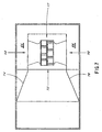
- FIGS. 4 and 5 show the basket in elevated and plan views.
- Each basket 14 consists of an open frame which has an internal ledge 120 upon which are placed a series of tubular structures 122 which are essentially rectangular in cross-section.
- the serrations are used to space battery plates longitudinally.
- the tubular structures 122 are movable along the basket ledge 120 in order to accommodate various widths of battery plates. It is understood by those skilled in the art that battery plates have tabs extending from them and that these tabs can be placed within the individual serrations in order to space the plates.
- Each end of the basket has a stainless steel inverted "V" shaped wire member 126 round in cross-section welded thereto; so that the upstanding apex of the "V” is located substantially on the center line of the basket.
- a rod 128 which has two hooked-shaped members 130, 132 welded to it is inserted down between the outermost edge of the basket and the inside sidewall of the housing 10 . This rod is then rotated 90° and lifted upwardly so that the hooks engage the respective apexes of the "V" shaped handles of the baskets 14.
- the hooks are placed a greater distance apart than the upstanding "V" shaped apexes so that the top hook engages first and begins to lift the top basket before the bottom hook engages and lifts the bottom basket.
- This basket design not only aids in air flow, but also in maximizing the number of plates that can be placed in a standard sized vessel.
- the basket is so dimensioned that there is only a slight clearance for the rods 128 to come down and engage the hooked-shaped members. This also aids in removing the baskets in that they will not, in practice, cock and jam upon withdrawal.
Landscapes
- Engineering & Computer Science (AREA)
- Mechanical Engineering (AREA)
- General Engineering & Computer Science (AREA)
- Chemical & Material Sciences (AREA)
- Combustion & Propulsion (AREA)
- Life Sciences & Earth Sciences (AREA)
- Sustainable Development (AREA)
- Drying Of Solid Materials (AREA)
Claims (29)
- Appareil destiné à sécher des plaques de batterie chargées possédant un boítier (10) pouvant maintenir intérieurement une pression de gaz positive, une chambre de séchage (16) disposée à l'intérieur dudit boítier et ayant un moyen (14) servant à soutenir des plaques de batterie devant être séchées dans une position telle que du gaz peut se déplacer sur les plaques, une chambre de combustion (21) disposée à l'intérieur dudit boítier et servant à fournir un gaz sec et chaud, sensiblement sans oxygène, à un moyen de soufflerie (17) qui souffle le gaz sur lesdites plaques afin d'effectuer le séchage des plaques en éliminant l'humidité de celles-ci, ledit appareil étant caractérisé par :un moyen (24, 26, 29, 30, 34, 36) de formation de nappe d'eau permettant de produire une nappe d'eau de refroidissement en écoulement de manière qu'elle soit en contact avec le gaz quittant lesdites plaques et qu'elle condense l'humidité retirée desdites plaques pendant le séchage ; etun moyen de commande de température servant à maintenir une certaine différence de température avec ladite chambre de séchage, ledit moyen de commande de température minimisant la chaleur utilisée pour compenser les pertes de chaleur dues à ladite condensation de l'humidité du gaz de séchage, de façon à minimiser l'énergie nécessaire pour élever la température du gaz de séchage, et ainsi maximiser le rendement thermique dudit appareil lors du séchage des plaques, le moyen de commande comportant des moyens (86 et 88) de mesure de la température de l'air respectivement en amont et en aval des plaques afin de commander la température régnant à l'intérieur de ladite chambre de séchage.
- Appareil selon la revendication 1, où la chambre de combustion comprend un foyer (78) dans la chambre de combustion (21), ledit foyer (78) comportant un carter (100) qui possède des éléments rapportés (102, 106) qui peuvent enlevés.
- Appareil selon la revendication 2, où les éléments rapportés (102, 106) pouvant être enlevés sont configurés de façon à produire des chambres communicantes, lesdites chambres canalisant l'air sec et chaud jusqu'à deux orifices d'évacuation (61, 64) proches des parois dudit boítier (10), lesdits orifices d'évacuation étant écartés l'un de l'autre.
- Appareil selon la revendication 2, où les éléments rapportés (102, 106) pouvant être enlevés comprennent également un élément d'écartement (104), ledit élément d'écartement (104) et lesdits éléments rapportés (102, 106) étant isolés (62) vis-à-vis du carter (100) du foyer.
- Appareil selon la revendication 2, où le foyer (78) possède une tige de foyer (108) ayant un tube de quartz (110) qui se prolonge autour de ladite tige de foyer (108) sur la plus grande partie de la longueur de celle-ci.
- Appareil selon la revendication 2, où un détecteur d'oxygène (112) communique avec ledit foyer (78).
- Appareil selon la revendication 1, où le moyen de formation de nappe d'eau produit une nappe d'eau qui s'écoule dans le sens opposé à celui de l'écoulement de l'air et qui comporte au moins une plate-forme (24, 29) placée au-dessous desdites plaques dans ledit boítier (10) suivant un angle propre à assurer un écoulement de l'eau par gravité; ladite plate-forme ayant des ailettes (34, 36) qui dirigent l'eau dans des nervures séparées (35) de celui-ci.
- Appareil selon la revendication 7, où de l'eau est introduite le long d'une partie supérieure de ladite plate-forme par un tuyau de tête (26, 30) possédant une pluralité de trous qui communiquent avec une nervure dressée verticalement (42, 43), de façon que l'eau courre régulièrement sur ladite plate-forme sans éclabousser.
- Appareil selon la revendication 7, où ladite plate-forme se termine par une paroi de retenue (31, 40) et des fentes (51) sont ménagées dans lesdites ailettes (34, 36) afin de permettre à l'eau de quitter ladite plate-forme et lesdites nervures (35).
- Appareil selon la revendication 7, où l'eau s'évacue dans une gouttière (58) et un capteur de température (90) est placé dans ladite gouttière afin de mesurer la température de l'eau sortant de ladite gouttière (58).
- Appareil selon la revendication 1, où ledit moyen de soufflerie (17) comprend des ventilateurs montés sur un arbre, ledit arbre étant porté par des paliers (79) montés à l'extérieur du boítier.
- Appareil selon la revendication 1, où ledit moyen de soufflerie (17) comprend au moins un ventilateur monté sur un axe positionné en aval du gaz chaud quittant la chambre de combustion, et une cheminée (89) est placée en une position postérieure à l'axe du ventilateur, ladite cheminée (89) ayant une ouverture limitée (118) à son extrémité inférieure, qui est positionnée pour s'ouvrir sur l'arrière du boítier à distance du gaz chaud sortant de la chambre de combustion.
- Appareil selon la revendication 12, où un capteur de température (116) est placé à la partie supérieure de ladite cheminée (89) à l'extérieur dudit boítier (10).
- Appareil selon la revendication 12, où un tube creux (115) est placé à l'intérieur de ladite cheminée (89), qui possède une extrémité communiquant avec ledit appareil approximativement au niveau du plan de l'axe (79) du moyen de soufflerie (17) et une autre extrémité communiquant par l'intermédiaire de l'extrémité externe de ladite cheminée (89), et un détecteur d'oxygène (114) est monté sur ladite extrémité, citée en premier, du tube creux (115) à l'opposé de l'extrémité extérieure audit boítier (10).
- Appareil selon la revendication 1, où le moyen servant soutenir les plaques de batterie devant être séchées comprend au moins un panier (14) ayant un rebord (120) sur lequel des râteliers (122) mobiles de façon réglable sont positionnés de façon à retenir lesdites plaques.
- Appareil selon la revendication 15, où lesdits râteliers (122) présentent des surfaces supérieures striées (124).
- Appareil selon la revendication 15, où lesdits paniers (14) ont des poignées (126) comprenant des tiges en forme de "V" retournés qui leur sont fixées ; et des moyens d'enlèvement (128, 130, 132) sont prévus de façon à venir en prise avec lesdites poignées en forme de "V" afin d'abaisser ledit panier dans ledit boítier ou de retirer ledit panier dudit boítier.
- Appareil selon la revendication 17, où ledit moyen d'enlèvement servant à abaisser ou enlever le panier comprend une tige (128) possédant au moins un crochet (130, 132), ladite tige étant placée et dimensionnée de façon à s'ajuster entre la paroi interne dudit boítier et la paroi externe dudit panier, de façon que, après qu'on y a inséré la tige et qu'on l'a ensuite fait tourner, au moment de l'enlèvement, ledit moyen d'enlèvement vient en prise avec ladite partie en forme de "V' de ladite poignée (126).
- Appareil selon la revendication 18, où on utilise une pluralité de paniers dans ledit appareil, et les crochets (103, 132) se trouvant sur ledit moyen d'enlèvement sont écartés les uns des autres d'une distance verticale supérieure à l'écartement vertical des poignées en forme de "V" (126) lorsque lesdits paniers sont empilés les uns sur les autres, de sorte que, lorsqu'on fait tourner lesdites tiges (128) et qu'on les enlève, un crochet supérieur (130) vient en prise avec la partie en forme de 'V" supérieure de la poignée d'un panier supérieur avant que le crochet inférieur (132) ne vienne en prise avec la partie en forme de "V" de la poignée du panier inférieur.
- Appareil selon la revendication 1, où l'appareil est dote d'un moyen formant une porte servant à ouvrir dans ledit boítier de façon à permettre que des paniers soient abaissés jusque dans ladite chambre, et permettant de fermer pour permettre que ledit appareil fonctionne dans le processus de séchage, ledit moyen porte possédant une porte articulée suivant un de ses bords et ayant un ou plusieurs agencements piston-cylindre fixés à ladite porte et audit boítier afin d'actionner ladite porte.
- Appareil selon al revendication 20, où ledit moyen porte possède une porte (12) dotée d'un joint étanche autour de son bord en correspondance avec ledit boítier, de façon à empêcher que l'oxygène ne fuit à l'intérieur pendant le traitement effectué par ledit appareil.
- Procédé de séchage de plaques de batterie chargées, comprenant les opérations suivantes :placer les plaques chargées dans un appareil comprenant une chambre de séchage (16) ;fournir un écoulement de gaz de séchage sensiblement dépourvu d'oxygène présentant une humidité relativement basse et dirigé de façon qu'il passe sur lesdites plaques afin de les sécher ;faire se condenser l'eau présente dans le gaz qui est passé sur les plaques pour les sécher,ledit procédé étant caractérisé par les opérations suivantes :faire passer ce gaz sur la surface d'une nappe d'eau s'écoulant dans un sens opposé à celui du gaz, sans introduire de gouttelettes d'eau dans le gaz ; etmaintenir la différence de température régnant à l'intérieur de ladite chambre de séchage de façon que la chaleur soit utilisée principalement pour sécher les plaques et, de façon minimale, pour réchauffer l'air relativement à la chaleur perdue du fait du processus de condensation effectuée dans ledit procédé, en mesurant (86) la température du gaz de séchage avant qu'il ne passe sur lesdites plaques, en mesurant (88) la température du gaz de séchage après qu'il a passé sur lesdites plaques ; en mesurant (90) la température de l'eau sortant dudit appareil ; et en régulant la température et le débit de ladite nappe d'eau en fonction de ces mesures.
- Procédé selon la revendication 22, où la température de l'eau qui sort est maintenue dans l'intervalle de 46° à 49°C (115° à 120°F) et, de manière préférée, à 46°C (115°F).
- Procédé selon la revendication 23, où l'écoulement de gaz sur la surface de la nappe d'eau est régulé de façon qu'il soit en deçà du débit qui provoquerait des "moutons".
- Procédé selon la revendication 22, où on empêche l'emballement thermique de ladite machine en mesurant (116) la température du gaz chaud dans la chambre de soufflerie en faisant passer ce gaz dans une ouverture limitée (118) proche de l'axe des ventilateurs (17) présents dans la machinerie et en lisant la température à l'intérieur de l'appareil.
- Procédé selon la revendication 22, où ledit gaz de séchage est chauffé dans une zone confinée et la teneur en oxygène dudit gaz est mesurée dans ladite zone confinée et au sortir de ladite zone confinée.
- Procédé selon la revendication 22, où le procédé de chauffage et de séchage de plaques comprend le confinement des plaques dans une zone fermée (10) qui a d'abord été purgée des gaz combustibles et le chauffage de l'air se trouvant dans ladite zone fermée jusqu'à ce que la température atteigne une valeur supérieure à 82°C (180°F), après quoi on introduit ladite nappe d'eau.
- Appareil selon la revendication 1, où la nappe d'eau s'écoule dans un sens opposé à celui du gaz quittant lesdites plaques.
- Appareil selon la revendication 1, où il est prévu une pluralité de nappes d'eau destinées à venir en contact avec ledit gaz qui quitte lesdites plaques.
Applications Claiming Priority (3)
| Application Number | Priority Date | Filing Date | Title |
|---|---|---|---|
| US22576094A | 1994-04-11 | 1994-04-11 | |
| US225760 | 1994-04-11 | ||
| PCT/US1995/003936 WO1995027878A1 (fr) | 1994-04-11 | 1995-04-10 | Appareil de charge a sec et procede associe |
Publications (3)
| Publication Number | Publication Date |
|---|---|
| EP0708904A1 EP0708904A1 (fr) | 1996-05-01 |
| EP0708904A4 EP0708904A4 (fr) | 1998-04-01 |
| EP0708904B1 true EP0708904B1 (fr) | 2003-02-05 |
Family
ID=22846116
Family Applications (1)
| Application Number | Title | Priority Date | Filing Date |
|---|---|---|---|
| EP95916918A Expired - Lifetime EP0708904B1 (fr) | 1994-04-11 | 1995-04-10 | Appareil et procédé pour sécher des plaques d'accumulateur chargées |
Country Status (4)
| Country | Link |
|---|---|
| EP (1) | EP0708904B1 (fr) |
| AU (1) | AU2379395A (fr) |
| DE (1) | DE69529551T2 (fr) |
| WO (1) | WO1995027878A1 (fr) |
Families Citing this family (7)
| Publication number | Priority date | Publication date | Assignee | Title |
|---|---|---|---|---|
| US8003156B2 (en) * | 2006-05-04 | 2011-08-23 | Advanced Cardiovascular Systems, Inc. | Rotatable support elements for stents |
| US8304012B2 (en) | 2006-05-04 | 2012-11-06 | Advanced Cardiovascular Systems, Inc. | Method for drying a stent |
| US7897195B2 (en) | 2007-06-15 | 2011-03-01 | Abbott Cardiovascular Systems Inc. | Devices for coating stents |
| CN102261829A (zh) * | 2011-04-30 | 2011-11-30 | 王幸正 | 一种极板干燥机的氧气控制系统 |
| CN103283057B (zh) * | 2011-08-31 | 2016-07-06 | 丰田自动车株式会社 | 汇流条模块、车辆用电源装置以及车辆 |
| CN110676502B (zh) * | 2019-09-04 | 2021-02-02 | 浙江长林电子有限公司 | 一种蓝牙耳机电池的制作方法 |
| CN111912198A (zh) * | 2020-08-25 | 2020-11-10 | 杭州数良科技有限公司 | 一种利用气压力密闭高温快速烘干搅拌的化妆品加工装置 |
Family Cites Families (5)
| Publication number | Priority date | Publication date | Assignee | Title |
|---|---|---|---|---|
| US2732631A (en) * | 1956-01-31 | Convfcyuk ukyu | ||
| US2484527A (en) * | 1945-02-01 | 1949-10-11 | Thomas H Rhoads | Method and apparatus for control of humidity |
| US3413728A (en) * | 1967-08-17 | 1968-12-03 | Tiegel Mfg Co | Method and apparatus for drying charged battery plates |
| US4099337A (en) * | 1976-12-13 | 1978-07-11 | Wauhop Jr Billy Joe | Method of curing concrete articles by water vaporization |
| US5040974A (en) * | 1990-03-27 | 1991-08-20 | Apv Baker Inc. | Internal air circulation system for lanham oven |
-
1995
- 1995-04-10 EP EP95916918A patent/EP0708904B1/fr not_active Expired - Lifetime
- 1995-04-10 AU AU23793/95A patent/AU2379395A/en not_active Abandoned
- 1995-04-10 WO PCT/US1995/003936 patent/WO1995027878A1/fr not_active Ceased
- 1995-04-10 DE DE69529551T patent/DE69529551T2/de not_active Expired - Lifetime
Also Published As
| Publication number | Publication date |
|---|---|
| DE69529551D1 (de) | 2003-03-13 |
| EP0708904A4 (fr) | 1998-04-01 |
| WO1995027878A1 (fr) | 1995-10-19 |
| EP0708904A1 (fr) | 1996-05-01 |
| DE69529551T2 (de) | 2003-11-20 |
| AU2379395A (en) | 1995-10-30 |
Similar Documents
| Publication | Publication Date | Title |
|---|---|---|
| US4787842A (en) | Air circulation and exhaust control system for commercial ovens | |
| US9228780B2 (en) | Method and apparatus for controlling cooling temperature and pressure in wood veneer jet dryers | |
| KR100811487B1 (ko) | 덕트리스 건조기 | |
| US8046932B2 (en) | Method and apparatus for inhibiting pitch formation in the wet seal exhaust duct of a veneer dryer | |
| US4384850A (en) | Recirculating air heater | |
| CA2206955C (fr) | Chauffe-eau, chauffant vers le bas, a base humide | |
| JP2002513909A (ja) | 再生式熱源完全統合型ウェブ乾燥機 | |
| WO1992017743A1 (fr) | Appareil et procede pour le sechage de substances cellulosiques et textiles au moyen de vapeur surchauffee | |
| EP0708904B1 (fr) | Appareil et procédé pour sécher des plaques d'accumulateur chargées | |
| US5673496A (en) | Dry charge machine and method | |
| US4941819A (en) | Air circulation and exhaust control system for commercial ovens | |
| CA2607017C (fr) | Procede et appareillage empechant la formation de poix dans le conduit d'evacuation a section d'etancheite humide d'un sechoir a placages | |
| FI100550B (fi) | Menetelmä ja laitteisto kasvisperäisen rouhemaisen polttoaineen poltta miseksi | |
| JP3679190B2 (ja) | 電池プレートの乾燥装置及び方法 | |
| CA2864368C (fr) | Procede et appareil de controle de la temperature de refroidissement et de la pression dans les sechoirs a tuyeres de placages | |
| US5433188A (en) | Fuel burning furnace | |
| WO1980000183A1 (fr) | Sechoir | |
| KR100703952B1 (ko) | 감압식열풍건조기 | |
| KR800000952Y1 (ko) | 어류 건조장치 | |
| KR870000771Y1 (ko) | 건조용 구명탄 온풍기 | |
| KR20000026728A (ko) | 콘덴싱 가스보일러용 연도 | |
| KR920004207B1 (ko) | 오염공기 정화 플랜트(a plant for purifying polluted air) | |
| MXPA01007510A (es) | Arreglo de percepcion de oxigeno de gas de escape de horno y circuito y metodo de control relacionados. | |
| JPS5837279Y2 (ja) | 連続海苔乾燥機 | |
| Stear | Control Technology and Energy Recovery |
Legal Events
| Date | Code | Title | Description |
|---|---|---|---|
| PUAI | Public reference made under article 153(3) epc to a published international application that has entered the european phase |
Free format text: ORIGINAL CODE: 0009012 |
|
| AK | Designated contracting states |
Kind code of ref document: A1 Designated state(s): DE FR GB IT |
|
| 17P | Request for examination filed |
Effective date: 19960416 |
|
| A4 | Supplementary search report drawn up and despatched |
Effective date: 19980212 |
|
| AK | Designated contracting states |
Kind code of ref document: A4 Designated state(s): AT BE CH DE DK ES FR GB GR IE IT LI LU MC NL PT SE |
|
| RBV | Designated contracting states (corrected) |
Designated state(s): DE FR GB IT |
|
| 17Q | First examination report despatched |
Effective date: 19990208 |
|
| GRAH | Despatch of communication of intention to grant a patent |
Free format text: ORIGINAL CODE: EPIDOS IGRA |
|
| RTI1 | Title (correction) |
Free format text: APPARATUS AND METHOD FOR DRYING CHARGED BATTERY PLATES |
|
| RTI1 | Title (correction) |
Free format text: APPARATUS AND METHOD FOR DRYING CHARGED BATTERY PLATES |
|
| GRAH | Despatch of communication of intention to grant a patent |
Free format text: ORIGINAL CODE: EPIDOS IGRA |
|
| GRAA | (expected) grant |
Free format text: ORIGINAL CODE: 0009210 |
|
| AK | Designated contracting states |
Designated state(s): DE FR GB IT |
|
| PG25 | Lapsed in a contracting state [announced via postgrant information from national office to epo] |
Ref country code: FR Free format text: LAPSE BECAUSE OF FAILURE TO SUBMIT A TRANSLATION OF THE DESCRIPTION OR TO PAY THE FEE WITHIN THE PRESCRIBED TIME-LIMIT Effective date: 20030205 |
|
| REG | Reference to a national code |
Ref country code: GB Ref legal event code: FG4D |
|
| REF | Corresponds to: |
Ref document number: 69529551 Country of ref document: DE Date of ref document: 20030313 Kind code of ref document: P |
|
| PLBE | No opposition filed within time limit |
Free format text: ORIGINAL CODE: 0009261 |
|
| STAA | Information on the status of an ep patent application or granted ep patent |
Free format text: STATUS: NO OPPOSITION FILED WITHIN TIME LIMIT |
|
| EN | Fr: translation not filed | ||
| 26N | No opposition filed |
Effective date: 20031106 |
|
| PGFP | Annual fee paid to national office [announced via postgrant information from national office to epo] |
Ref country code: GB Payment date: 20140409 Year of fee payment: 20 |
|
| PGFP | Annual fee paid to national office [announced via postgrant information from national office to epo] |
Ref country code: IT Payment date: 20140417 Year of fee payment: 20 Ref country code: DE Payment date: 20140430 Year of fee payment: 20 |
|
| REG | Reference to a national code |
Ref country code: DE Ref legal event code: R071 Ref document number: 69529551 Country of ref document: DE |
|
| REG | Reference to a national code |
Ref country code: GB Ref legal event code: PE20 Expiry date: 20150409 |
|
| PG25 | Lapsed in a contracting state [announced via postgrant information from national office to epo] |
Ref country code: GB Free format text: LAPSE BECAUSE OF EXPIRATION OF PROTECTION Effective date: 20150409 |