EP0708964B1 - Transportvorrichtung mit schraubenförmiger abtastung für einspulenbandkassette - Google Patents
Transportvorrichtung mit schraubenförmiger abtastung für einspulenbandkassette Download PDFInfo
- Publication number
- EP0708964B1 EP0708964B1 EP94917997A EP94917997A EP0708964B1 EP 0708964 B1 EP0708964 B1 EP 0708964B1 EP 94917997 A EP94917997 A EP 94917997A EP 94917997 A EP94917997 A EP 94917997A EP 0708964 B1 EP0708964 B1 EP 0708964B1
- Authority
- EP
- European Patent Office
- Prior art keywords
- tape
- cartridge
- helical
- transport
- assembly
- Prior art date
- Legal status (The legal status is an assumption and is not a legal conclusion. Google has not performed a legal analysis and makes no representation as to the accuracy of the status listed.)
- Expired - Lifetime
Links
- 230000032258 transport Effects 0.000 description 97
- 238000005516 engineering process Methods 0.000 description 12
- 238000013500 data storage Methods 0.000 description 7
- 238000012545 processing Methods 0.000 description 4
- 230000036316 preload Effects 0.000 description 3
- 238000011161 development Methods 0.000 description 2
- 238000012986 modification Methods 0.000 description 2
- 230000004048 modification Effects 0.000 description 2
- 238000009420 retrofitting Methods 0.000 description 2
- 235000004443 Ricinus communis Nutrition 0.000 description 1
- 240000000528 Ricinus communis Species 0.000 description 1
- 238000001816 cooling Methods 0.000 description 1
- 238000013461 design Methods 0.000 description 1
- 239000000428 dust Substances 0.000 description 1
- 230000002452 interceptive effect Effects 0.000 description 1
- 230000013011 mating Effects 0.000 description 1
- 238000000034 method Methods 0.000 description 1
- 235000012459 muffins Nutrition 0.000 description 1
- 230000000135 prohibitive effect Effects 0.000 description 1
- 210000000352 storage cell Anatomy 0.000 description 1
- 238000012546 transfer Methods 0.000 description 1
Images


Classifications
-
- G—PHYSICS
- G11—INFORMATION STORAGE
- G11B—INFORMATION STORAGE BASED ON RELATIVE MOVEMENT BETWEEN RECORD CARRIER AND TRANSDUCER
- G11B15/00—Driving, starting or stopping record carriers of filamentary or web form; Driving both such record carriers and heads; Guiding such record carriers or containers therefor; Control thereof; Control of operating function
- G11B15/675—Guiding containers, e.g. loading, ejecting cassettes
- G11B15/68—Automatic cassette changing arrangements; automatic tape changing arrangements
- G11B15/682—Automatic cassette changing arrangements; automatic tape changing arrangements with fixed magazines having fixed cassette storage cells, e.g. in racks
- G11B15/6835—Automatic cassette changing arrangements; automatic tape changing arrangements with fixed magazines having fixed cassette storage cells, e.g. in racks the cassettes being transferred to a fixed recorder or player using a moving carriage
-
- G—PHYSICS
- G11—INFORMATION STORAGE
- G11B—INFORMATION STORAGE BASED ON RELATIVE MOVEMENT BETWEEN RECORD CARRIER AND TRANSDUCER
- G11B15/00—Driving, starting or stopping record carriers of filamentary or web form; Driving both such record carriers and heads; Guiding such record carriers or containers therefor; Control thereof; Control of operating function
- G11B15/60—Guiding record carrier
- G11B15/61—Guiding record carrier on drum, e.g. drum containing rotating heads
-
- G—PHYSICS
- G11—INFORMATION STORAGE
- G11B—INFORMATION STORAGE BASED ON RELATIVE MOVEMENT BETWEEN RECORD CARRIER AND TRANSDUCER
- G11B15/00—Driving, starting or stopping record carriers of filamentary or web form; Driving both such record carriers and heads; Guiding such record carriers or containers therefor; Control thereof; Control of operating function
- G11B15/60—Guiding record carrier
- G11B15/66—Threading; Loading; Automatic self-loading
- G11B15/67—Threading; Loading; Automatic self-loading by extracting end of record carrier from container or spool
Definitions
- the invention relates generally to the storage of data on magnetic recording tape, and more specifically, to the storage of digital data in helical format on a magnetic tape housed within a single reel tape cartridge.
- the data processing industry stores large amounts of digital data on magnetic tapes.
- the 3480 tape cartridge (developed by IBM Corporation, Armonk, New York, U.S.A.) is an industry standard for magnetic storage media.
- the 3480 cartridge is a single reel cartridge with a length of 12,7 mm (1/2 inch) wide magnetic tape stored on it.
- the cartridge housing protects the tape from damage while allowing the tape reel to be driven from a drive mechanism on the underside of the cartridge housing.
- the tape is withdrawn from an opening formed at one corner of the cartridge.
- a leader block attached to a free end of the tape allows the tape to be withdrawn from the cartridge for read/write operations.
- Read/write operations are performed by a tape "transport.”
- the standard tape transport accepts the tape cartridge into an elevator assembly.
- a threading mechanism grabs the leader block and pulls it free from the cartridge.
- the leader block is then used to thread the tape through a series of guide posts, across a longitudinal read/write head, and into a slot in a take-up reel. Once threaded, the tape from the cartridge can be driven across the read/write heads for data transfer operations.
- the standard 3480 cartridge contain 165m (541 feet) of tape. Data is stored on the tape in an 18 track format, typically providing approximately 200 MB (megabytes) of data storage capacity.
- the 4400 automated cartridge system (ACS) from Storage Technology Corporation, Louisville, Colorado, U.S.A., is capable of storing up to 6,000 3480 cartridges.
- the 4400 ACS can quickly locate a selected cartridge and load it into a cartridge transport for read/write operations.
- the Model 4400 ACS typically has between one and four cartridge transports associated with it.
- the 4400 ACS has proven to be a cost-effective data storage system. With each of 6,000 cartridges providing 200 megabytes of storage capacity, one 4400 ACS has a total capacity of 1.2 terabytes (1.2 x 10 12 bytes). This storage capacity is provided in a unit that occupies approximately 9,3m 2 (100 square feet) of floor space. Nevertheless, it is desirable to increase the storage density of the 4400 ACS.
- Data is currently stored on a 3480 cartridge in an 18 track longitudinal format.
- a helical scan data storage format would allow approximately a 100 times increase in storage capacity.
- the typical 3480 cartridge would have a helical scan storage capacity of 25 gigabytes rather than the 200 megabytes of the longitudinal format.
- the 4400 ACS would provide a total storage capacity of 150 terabytes.
- helical-scan technology holds promise for increasing the storage capacity of the 4400 ACS by a factor of greater than 100 by simply changing the format with which data is stored in each tape cartridge.
- the helical scan transport is quite different than the longitudinal style transport.
- the helical scan transport includes a cylindrical rotating head around which the tape must be wrapped for read/write operations.
- the helical scan tape path is much more complex than the path for longitudinal transports.
- the video industry has adopted a two reel magnetic tape cassette as its standard media. Loading of the tape from a cassette through the tape path of a helical scan transport is straightforward and well known in the art. The loading of tape from a cartridge through a helical scan tape path, however, is more difficult and has not been developed to the level of that for a cassette. Thus, two standard and distinct media form factors have developed for the video industry and the data processing industry. The form factors are incompatible. 3480 style cartridges cannot be used with the helical-scan cassette transports of the video industry.
- volumetric economy By not including a take-up reel, the cartridge is roughly one-half the size of a cassette for the same tape length. Thus, a cartridge has twice the storage capacity per unit volume of a cassette.
- frontal surface area An important feature of the form factor of such a transport is the frontal surface area. That is, the front face of the transport which contains the opening for accepting a tape cartridge must be small enough to interface with other equipment. Form factors such as that disclosed by Leonhardt et al. in US-A-5 128 815 may have too large a frontal area for many applications because of the side-by-side arrangement of the cartridge and the take-up reel, and it is an object of the invention to overcome this.
- the invention is a helical scan transport for a magnetic tape cartridge having the characterising features of appended claim 1.
- the transport has a substantially linear tape loading path and a form factor which allows its use with a Storage Technology Corporation Model 4400 automated cartridge system (also known as a data cartridge storage "library").
- a new helical scan tape cartridge was developed for use with the transport of the invention.
- the helical cartridge has a form factor similar to the 3480 style cartridge.
- the 4400 ACS can store both the helical cartridges and the 3480 style cartridges.
- the helical scan transport apparatus of the invention includes a chassis having a front end portion and a rear end portion.
- An elevator assembly is mounted on the chassis at the front end.
- the elevator assembly is configured to receive a tape cartridge and to position the tape cartridge in a loaded position.
- a take-up reel assembly is coupled to the chassis at the rear end portion.
- a helical deck is mounted on a central portion of the chassis between the elevator assembly and the take-up reel assembly.
- the helical deck includes a rotary read/write head, a substantially linear tape loading path between the elevator assembly and the take-up reel assembly, and movable guides for seizing the tape from the tape loading path and for at least partially wrapping the tape around the rotary head.
- a linear threading mechanism is configured to grasp the leader block of the tape, thread the tape through the tape loading path of the helical deck, and couple the leader block to the take-up reel assembly.
- the helical deck is taken from a commercially available Panasonic Model D350 digital video cassette recorder.
- the helical transport is dimensioned to fit within a rectangular enclosure measuring approximately 32 cm (12.5") wide by 67 cm (26.5") deep and configured such that a plurality of the transport apparatuses may be stacked within the enclosure with a vertical spacing of 28 cm (11.06") on center.
- the front end portion of the chassis extends 17,8 cm (7.0") outward from the enclosure and is configured to mate with the 4400 automated cartridge system when the enclosure is coupled to a housing of the 4400 automated cartridge system.
- the rectangular enclosure is a frame assembly configured to enclose up to four of the helical transports of the invention.
- the enclosure measures 67 cm (26.5") deep by 71,1 cm (28.0") wide by 172 cm (67.775") high (not including castors).
- the enclosure houses each transport and its associated electronic circuitry in a side-by-side arrangement.
- the transport fills approximately 31,2 cm (12.3") of the width and the remaining width is available for a power supply and the electronic circuitry associated with the transport.
- US-A-4 399 959 discloses a relatively linear threading mechanism.
- a channel which is substantially in the same plane as the guideposts and the magnetic head.
- Such an arrangement could not be used since the channel in US-A-4 399 959 and the drive mechanism would interfere with the base plate of the helical deck.
- the invention is a helical scan transport for a magnetic tape cartridge.
- the transport has a substantially linear tape loading path and a form factor which allows its use with a Storage Technology Corporation Model 4400 automated cartridge system or ACS.
- the transport is dimensioned to fit within a rectangular enclosure (i.e., a cartridge drive unit) measuring approximately 71 cm (28") wide by 67 cm (26.5") deep and configured such that a plurality of the transports may be stacked within the enclosure with a vertical spacing of 28 cm (11.06") on center.
- the transport itself is 31,2 cm (12.3") wide.
- the additional space is used for the associated electronic circuitry.
- the transport includes a front end portion (for receiving a helical data cartridge) which extends outward 17,8 cm (7") from the enclosure. The front end portion of the transport is configured to mate with the 4400 automated cartridge system when the enclosure is coupled to a housing of the 4400 automated cartridge system.
- the inventors have discovered that the costs involved with developing a helical scan transport for a single reel cartridge are prohibitive. Development of the required head assembly, servo controls, and data path (i.e., read/write electronics between the head assembly and the input/output data channels) are extremely high. This may account for the fact that such a device is not commercially available. In overcoming this problem, the inventors have further discovered that a double reel cassette type helical scan video transport could be adapted to produce a single reel cartridge transport which meets the required form factor for use with a 4400 ACS. By using the head assembly, the servo controls and the data path from the video transport, development costs were minimized and time to market was greatly reduced. The resulting helical scan transport allows the storage capacity of the 4400 ACS to be increased from approximately 1.2 terabytes to approximately 150 terabytes. This is over a 100 times increase in storage capacity without requiring modification to the 4400 ACS.
- a new helical scan tape cartridge was developed for use with the transport of the invention.
- the helical cartridge has a form factor similar to the 3480 cartridge.
- the 4400 ACS can store both helical cartridges and 3480 cartridges.
- the new helical transport and helical cartridge can coexist in a 4400 ACS environment with the 4480 transport (and other Model 4400 ACS compatible longitudinal-format transports) and the 3480 cartridge.
- the helical cartridges bear identification marking so that the 4400 ACS can distinguish a helical cartridge from a 3480 cartridge and route each cartridge to an appropriate transport.
- ACS 100 includes a housing 102.
- Housing 102 is a substantially circular shaped housing having twelve substantially flat sides. Each side is approximately 36 inches wide.
- the overall housing 102 is approximately 128 inches in diameter and 92 inches high.
- housing 102 encloses a robot assembly and a plurality of data cartridge storage cells or bins 118 (see Figure 2).
- Cartridge drive assembly 200 includes a frame assembly 202 for housing a plurality (e.g., four) of helical cartridge transports 204 (not shown in Figure 1).
- Cartridge drive unit 200 mates with a side of housing 102 via a drive opening 108.
- Drive opening 108 is a substantially rectangular recess approximately 50 inches high by 40,6cm (16") wide by 17,8cm (7") deep.
- a rear wall of opening 108 forms a template 110.
- Template 110 includes a plurality of cassette openings 114 and locating holes 116.
- Template 110 is configured to mate with each transport 204 so that cartridge opening 114 mates with a front face 206 of cartridge transport 204 and a cartridge may be passed through opening 114 and into an elevator assembly 208 (see Figure 6).
- Locating holes 116 are configured to mate wit alignment pins 210 (see Figure 3) of cartridge transport 204.
- FIG. 2 is a cross-sectional top view of ACS 100 showing ACS housing 102 and cartridge drive unit 200.
- Cartridge transport 204 is illustrated within cartridge drive unit 200.
- a plurality of cartridge storage bins 118 within housing 102 are also depicted.
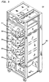
- FIG 3 is a perspective view of cartridge drive unit 200 with the side and top panels removed from frame assembly 202.
- Four cartridge transports 204 are shown mounted within frame assembly 202.
- front face 206 of each cartridge transport 204 is covered by a dust cover 213 which includes an opening 214 configured to accept passage of a tape cartridge into elevator assembly 208.
- Frame assembly 202 is configured to accept mounting of one, two, three or four cartridge transports 204.
- transports 204 extend out from the front face of cartridge drive unit 200 for mating with template 110 of ACS 100. Note also that transports 204 are located to the right side of frame assembly 202. Much of the electronic circuitry for each transport 204 is positioned in frame assembly 202 to the left side of each transport 204 in an electronics area 211. This is further illustrated in Figures 4 and 5.
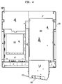
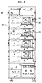
- FIG 4 is a cross-sectional top view and Figure 5 is a front view of cartridge drive unit 200.
- Cartridge drive unit 200 is 67,3 cm (26.5") deep by 71 cm (28") wide by 172cm (67.8") high (not including casters).
- Cartridge drive unit 200 is configured to mate with ACS housing 102 without physically interfering with other ACS subsystems which may be part of or coupled to housing 102. These include slave ACS's, additional cartridge drives, control units, and access doors.
- transport 202 In order for the helical transport 202 of the invention to be compatible with cartridge drive unit 200 and ACS 100, transport 202 must fit within frame assembly 204. Front end 212 of transport 202 must extend approximately 17,7 cm (7") out from frame assembly 202. In addition, the height of each transport 204 must be limited so that a vertical distance of 28,1 cm (11.08") is maintained between alignment pins 210 of adjacently stacked transports 204. This will allow the front faces 206 of the transports 204 to precisely mate with the cartridge openings 114 and locating holes 116 in drive opening 108 of ACS housing 102.
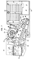
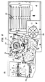
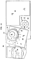
- FIG. 6 is a perspective view
- Figure 7 is a top view
- Figure 9 is a right side view
- Figure 10 is a left side view of helical scan transport 204.
- Figure 8 is a top view of transport 200 with linear threading mechanism 218 removed.
- Transport 200 includes an elevator assembly 208, a helical deck 216, a take-up reel 236, a linear threading mechanism 218, a circuit card area 220, and a transport chassis 234.
- Elevator assembly 208 is configured to receive a tape cartridge and to load the cartridge into transport 204.
- Helical deck 204 includes a rotary scan head 222, a loading ring 224, and a plurality of guide posts and capstans which make up a tape path (discussed below).
- Linear threading mechanism 218 includes a linear bearing 226, a threading arm 228, and a threading cam 230.
- Circuit board area 220 includes a plurality of D-type printed circuit board connectors for connecting to a plurality of printed circuit boards containing electronic circuitry for transport 204.
- An opening 232 in chassis 234 is configured to accept mounting of a muffin fan for cooling the electronic circuitry of transport 300.
- Helical deck 216 includes a tape path and associated guides, a supply reel drive assembly (not shown), a take-up reel assembly, and all associated servo control circuitry.
- Helical deck 216 further includes complex electronic circuitry associated with the read/write data path.
- the inventors have taken helical deck 216 from a commercially available device and adapted it for use in helical transport 204.
- helical deck 216 is taken from an AJ-D350 12,7 mm (1/2") digital studio video tape recorder available from Panasonic Broadcasts Systems Co., Secaucus, New Jersey.
- the Panasonic D350 is a video tape recorder configured to be used with 12,7 mm (1/2") video cassettes. It will not accept a 3480 tape cartridge. Accordingly, the inventors have taken only the helical deck (including the read/write electronics, data path, servo controls and motors, and the associated electronic circuitry) from the Panasonic D350.
- the helical deck including the read/write electronics, data path, servo controls and motors, and the associated electronic circuitry
- the inventors have produced a transport configuration which will allow the D350 deck to be used with a tape cartridge while maintaining a form factor compatible with the Storage Technology Corporation Model 4400 ACS.
- a cartridge loading mechanism (elevator assembly 208) and a tape threading mechanism (linear threading mechanism 218) work together in providing the tape to helical deck 216 in a format such that helical deck 310 "sees" a cassette.
- linear threading mechanism 218 tape control can then be turned over to the D350 helical deck.
- the servo controls were designed to feed tape from a supply reel of a cassette in a counter-clockwise direction and to wind the tape on a take up reel (within the cassette), also in a clockwise direction.
- the standard 3480 cartridge requires that the supply reel be turned in a counter clockwise direction to feed the tape. Accordingly, in order to use the servo control circuits and motors of the Panasonic D350, a new tape cartridge had to be developed.
- the new helical cartridge has essentially the same dimensions and features as the 3480 cartridge. However, the helical cartridge feeds tape from the take-up reel when it is turned in a clockwise direction. Thus, the tape feeds from a front, left-side corner of the cartridge rather than a front, right-side corner as in the 3480 cartridge. Since the dimensions and other features of the helical cartridge are substantially the same as the 3480 cartridge, the helical cartridge may be used in the Model 4400 ACS.
- the 3480 cartridge and the new helical cartridge have the same essential dimensions and features. Therefore, they are hereafter referred to as "3480-style" cartridges.
- helical transport 204 may coexist in an ACS 100 environment with other transports (e.g., the Storage Technology Corporation 4480).
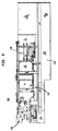
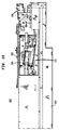
- helidal transport 204 In order to meet the conflicting requirements of producing a helidal transport (1) with a form factor compatible with ACS 100, (2) which uses a tape cartridge compatible with ACS 100 (i.e., can be stored in bins 118 and manipulated by a robot mechanism of the ACS); and (3) which uses a commercially available helical deck; the components of helical transport 204 were configured and arranged as illustrated in Figures 7-10. The dimensions of the preferred embodiment are shown in Figure 11.
- Figure 11 also illustrates the tape path 338.
- the leader block of the tape is pulled under guide post A; over guide posts B, C, D, E, F and G; under guide post H; and into take-up reel 236.
- Guide posts A and H are fixed position guide posts of helical deck 216.
- Guide posts E and F are mounted on loading ring 224 and move therewith to load the tape around helical head 222 for data read/write operations.
- Guide post G is part of the incline post assembly of helical deck 216.
- Guide post D is a fixed post added by the inventors. It is not part of the Panasonic D350 helical deck.
- tape control can be turned over to helical deck 216.
- Helical deck 216 may then load the tape around head 222 as is known in the art.
- the transport of the invention has been described in the environment of a Storage Technology Corporation Model 4400 ACS. It will be apparent to a person skilled in the art, however, that the transport of the invention may be used with other automated cartridge systems. These include the Storage Technology Corporation WOLFCREEKTM ACS, the Storage Technology Corporation POWDERHORNTM ACS, and the 3495 ACS available from IBM Corporation, Armonk, New York. Each of these ACS's currently store data in a longitudinal recording format on a 3480 cartridge. Moreover, the transport of the invention may be used with any single reel tape cartridge and is not limited to the 3480-style cartridge.
Landscapes
- Automatic Tape Cassette Changers (AREA)
- Adhesive Tapes (AREA)
Claims (4)
- Spiralförmiges Abtast-Transport-Gerät (204) zum Einlesen und Beschreiben von Daten auf ein magnetisches Aufnahmeband, das auf eine Zuführrolle gewickelt ist, die drehbar innerhalb einer entfernbaren Bandkassette befestigt ist, in welcher das Band einen Führungsblock aufweist, der an einem Ende zur Verwendung beim Herausziehen des Endes aus der Bandkassette befestigt ist, wobei das Transportgerät umfaßt:ein Gestell (234), das einen vorderen Endabschnitt (206) und einen hinteren Endabschnitt aufweist;eine Aufzugsanordnung (208), die auf dem Gestell an dem vorderen Ende befestigt ist, wobei die Aufzugsanordnung angeordnet ist, um die Bandkassette aufzunehmen und die Bandkassette in eine eingelegte Position zu positionieren;eine Aufnahmerollen-Anordnung (236), die mit dem Gestell an dem hinteren Endabschnitt verbunden ist;ein spiralförmiges Laufwerk (216), das auf einen zentralen Abschnitt des Gestells zwischen der Aufzugsanordnung und der Aufnahmerollen-Anordnung befestigt ist, wobei das spiralförmige Laufwerk einen rotierenden Lese/Schreibkopf (222) umfaßt, einen Bandeinlegepfad zwischen der Aufzugsanordnung und der Aufnahmerollen-Anordnung sowie bewegliche Führungen (E, F), um das Band von dem Bandeinlegepfad aufzunehmen, und wenigstens teilweise um den rotierenden Kopf herum zu wickeln; undein Einfädelmechanismus (218), der einen Einfädelarm (228) umfaßt, der angeordnet ist, um den Führungsblock des Bandes zu ergreifen, das Band durch den Bandeinlegepfad des spiralförmigen Laufwerks einzuführen und den Fübrungsblock mit der Aufnahmerollen-Anordnung zu verbinden; dadurch gekennzeichnet, daß der Einfädelmechanismus (218) ferner einen linearen Halter (226) umfaßt, der linear entlang des gesamten Einlegepfades des Bandes ist, um den Einfädelarm (228) zu führen; und einen Einfädelnocken (230), wobei der Einfädelmechanismus angehoben über dem spiralförmigen Laufwerk angeordnet ist.
- Spiralförmiges Abtast-Transport-Gerät nach Anspruch 1, das ferner eine Zuführrollen-Antriebseinheit umfaßt, die zusammen mit der Aufzugseinheit angeordnet ist, wobei die Zuführrollen-Antriebseinheit konfiguriert ist, um an die Zuführrolle der Kassette zu koppeln und die Zuführrolle drehbar anzutreiben, die im hinteren Bereich relativ zu dem spiralförmigen Laufwerk befestigt ist.
- Spiralförmiges Abtast-Transport-Gerät nach Anspruch 1 oder 2, bei welchem die Aufnahmerollen-Anordnung eine Aufnahmerolle und einen Servomotor umfaßt, der an die Aufnahmerolle gekoppelt ist, die im hinteren Bereich des Gestells relativ zu dem spiralförmigen Laufwerk angeordnet ist.
- Spiralförmiges Abtast-Transport-Gerät nach irgendeinem vorhergehenden Ansprach, in welchem der Transport dimensioniert ist, um in eine rechteckförmige Ummantelung zu passen, die ungefähr 0,318m (12,5") in der Breite und 0,673m (26,5") in der Tiefe mißt und derart konfiguriert ist, daß eine Vielzahl der Transportgeräte in der Ummantelung mit einer vertikalen Beabstandung von 0,279m (11") in der Mitte gestapelt werden kann, wobei das Transportgerät und die Ummantelung zur Verwendung mit einem automatischen Kassettensystem geeignet ist; in welchemder vordere Endbereich sich 0,178m (7") nach außen von der Ummantelung erstreckt und konfiguriert ist, um in das automatische Kassettensystem zu passen, wenn die Ummantelung an ein Gehäuse des automatischen Kassettensystems gekoppelt ist; und in welchemdie Aufzugseinheit konfiguriert ist, um eine Bandkassette von dem automatischen Kassettensystem aufzunehmen.
Applications Claiming Priority (3)
| Application Number | Priority Date | Filing Date | Title |
|---|---|---|---|
| US6065393A | 1993-05-13 | 1993-05-13 | |
| US60653 | 1993-05-13 | ||
| PCT/US1994/005444 WO1994027292A1 (en) | 1993-05-13 | 1994-05-13 | Helical scan transport for single reel tape cartridge |
Publications (3)
| Publication Number | Publication Date |
|---|---|
| EP0708964A1 EP0708964A1 (de) | 1996-05-01 |
| EP0708964A4 EP0708964A4 (de) | 1996-07-10 |
| EP0708964B1 true EP0708964B1 (de) | 2000-06-28 |
Family
ID=22030932
Family Applications (1)
| Application Number | Title | Priority Date | Filing Date |
|---|---|---|---|
| EP94917997A Expired - Lifetime EP0708964B1 (de) | 1993-05-13 | 1994-05-13 | Transportvorrichtung mit schraubenförmiger abtastung für einspulenbandkassette |
Country Status (7)
| Country | Link |
|---|---|
| US (1) | US6577467B2 (de) |
| EP (1) | EP0708964B1 (de) |
| JP (1) | JPH09500227A (de) |
| AU (1) | AU6950594A (de) |
| CA (1) | CA2162892A1 (de) |
| DE (1) | DE69425059T2 (de) |
| WO (1) | WO1994027292A1 (de) |
Families Citing this family (5)
| Publication number | Priority date | Publication date | Assignee | Title |
|---|---|---|---|---|
| KR100848122B1 (ko) * | 2000-11-02 | 2008-07-24 | 소니 가부시끼 가이샤 | 1 릴테이프 카트리지 및 이것을 이용한 기록재생장치 |
| US7327534B2 (en) * | 2004-09-01 | 2008-02-05 | Sony Corporation | Ultra fast backup (UFB) tape cartridge and method for loading same |
| US7142383B2 (en) | 2004-09-01 | 2006-11-28 | Sony Corporation | Ultra Fast Backup (UFB) track concept and method for recording same |
| US6992847B1 (en) | 2004-09-01 | 2006-01-31 | Sony Corporation | Linear sliding tape scanner and method for using same |
| JP2013522808A (ja) * | 2010-03-23 | 2013-06-13 | テラダイン、 インコーポレイテッド | 手動ローディングを使用する記憶装置のバルク搬送 |
Family Cites Families (13)
| Publication number | Priority date | Publication date | Assignee | Title |
|---|---|---|---|---|
| US3818503A (en) * | 1971-12-01 | 1974-06-18 | Matsushita Electric Industrial Co Ltd | Rotary head type magnetic recording and reproducing apparatus |
| JPS5421722B2 (de) * | 1972-02-21 | 1979-08-01 | ||
| JPS57117154A (en) * | 1981-01-14 | 1982-07-21 | Hitachi Ltd | Automatic loading device of tape |
| US4399959A (en) * | 1981-10-26 | 1983-08-23 | International Business Machines Corp. | Constant force windup spring web threading system |
| US4991037A (en) * | 1986-03-26 | 1991-02-05 | Copal Co., Ltd. | Apparatus for manipulating a magnetic tape cartridge and the magnetic tape contained therewithin |
| US4928245A (en) * | 1987-01-27 | 1990-05-22 | Storage Technology Corporation | Automated cartridge system |
| US5128815A (en) * | 1990-12-06 | 1992-07-07 | Storage Technology Corporation | Apparatus for interfacing a cartridge tape with a helical scan transport |
| US5202809A (en) * | 1991-05-13 | 1993-04-13 | Storage Technology Corporation | Magnetic tape cartridge for helical scan transports with a single reel |
| US5325370A (en) * | 1991-11-12 | 1994-06-28 | Storage Technology Corporation | Method and apparatus for recording data on magnetic tape media |
| JPH06274985A (ja) * | 1993-03-17 | 1994-09-30 | Hitachi Ltd | テープレコーダ |
| US5374003A (en) * | 1993-04-07 | 1994-12-20 | Storage Technology Corporation | Tape threading system for a helical tape drive |
| US5478021A (en) * | 1993-10-05 | 1995-12-26 | Storage Technology Corporation | Apparatus and method for optimized threading of a tape along a curvilinear tape path |
| US5629815A (en) * | 1993-11-22 | 1997-05-13 | Storage Technology Corp. | Apparatus and method for reducing head wear in helical scan tape transport |
-
1994
- 1994-05-13 CA CA002162892A patent/CA2162892A1/en not_active Abandoned
- 1994-05-13 AU AU69505/94A patent/AU6950594A/en not_active Abandoned
- 1994-05-13 DE DE69425059T patent/DE69425059T2/de not_active Expired - Fee Related
- 1994-05-13 JP JP6525767A patent/JPH09500227A/ja active Pending
- 1994-05-13 WO PCT/US1994/005444 patent/WO1994027292A1/en not_active Ceased
- 1994-05-13 EP EP94917997A patent/EP0708964B1/de not_active Expired - Lifetime
-
2002
- 2002-01-28 US US10/059,915 patent/US6577467B2/en not_active Expired - Lifetime
Also Published As
| Publication number | Publication date |
|---|---|
| CA2162892A1 (en) | 1994-11-24 |
| DE69425059D1 (de) | 2000-08-03 |
| DE69425059T2 (de) | 2001-03-22 |
| US6577467B2 (en) | 2003-06-10 |
| WO1994027292A1 (en) | 1994-11-24 |
| AU6950594A (en) | 1994-12-12 |
| EP0708964A1 (de) | 1996-05-01 |
| JPH09500227A (ja) | 1997-01-07 |
| EP0708964A4 (de) | 1996-07-10 |
| US20020105753A1 (en) | 2002-08-08 |
Similar Documents
| Publication | Publication Date | Title |
|---|---|---|
| US7483236B2 (en) | Media cartridge storage device for an autoloading data storage and retrieval system | |
| US5469310A (en) | Automated cassette loader | |
| US5715216A (en) | Data storage method having a columnar array of storage receptacles that also are input-output and a data device at one end of the columnar array | |
| US20080094752A1 (en) | Housing for information storage medium and method using same | |
| KR19990082744A (ko) | 자동화된데이터저장장치라이브러리용패스스루및로드/언로드 | |
| EP1278190B1 (de) | Bandkassettentransportmagazin für automatisches Bibliotheksystem mit automatischer Ladung von Bandkassetten | |
| EP0708964B1 (de) | Transportvorrichtung mit schraubenförmiger abtastung für einspulenbandkassette | |
| US5333810A (en) | Raised linear threading mechanism for a tape transport system | |
| US6985328B2 (en) | One and three quarters inch form factor tape cartridge autoloader | |
| US6498771B1 (en) | Data storage unit having plural removable magazines | |
| US20030030938A1 (en) | Automatic changer for cartridge-type recording medium | |
| CA2102909A1 (en) | Magnetic tape cartridge for helical scan transports | |
| US5979814A (en) | Invertible portable container having two separate lengths of recording tape | |
| JP4061733B2 (ja) | カセットライブラリシステム | |
| US8488269B2 (en) | Library apparatus | |
| US7057847B2 (en) | Media storage systems and cartridge-handling apparatus therefor | |
| US6508428B2 (en) | Multi-purpose wide media cartridges and cartridge chassis subassemblies | |
| US6809897B2 (en) | Direct threading helical tape path for single-reel tape cartridge | |
| US6663034B1 (en) | Data storage tape cartridge with datum pads for registration with a tape drive | |
| JP2847327B2 (ja) | テープカートリッジシステムにおけるローダ機構 | |
| JP2004030750A (ja) | カセット自動供給装置及び複数のカセット自動供給装置を備えるカセット自動供給システム | |
| JP2004348862A (ja) | 記録メディアカートリッジ | |
| JPH0298865A (ja) | 大容量補助記憶・検索装置 | |
| JPH06111438A (ja) | 磁気テープ装置 | |
| JPS6350955A (ja) | 磁気テ−プ装置 |
Legal Events
| Date | Code | Title | Description |
|---|---|---|---|
| PUAI | Public reference made under article 153(3) epc to a published international application that has entered the european phase |
Free format text: ORIGINAL CODE: 0009012 |
|
| 17P | Request for examination filed |
Effective date: 19951130 |
|
| AK | Designated contracting states |
Kind code of ref document: A1 Designated state(s): BE CH DE ES FR GB IE IT LI SE |
|
| A4 | Supplementary search report drawn up and despatched |
Effective date: 19960521 |
|
| AK | Designated contracting states |
Kind code of ref document: A4 Designated state(s): BE CH DE ES FR GB IE IT LI SE |
|
| 17Q | First examination report despatched |
Effective date: 19980304 |
|
| GRAG | Despatch of communication of intention to grant |
Free format text: ORIGINAL CODE: EPIDOS AGRA |
|
| GRAG | Despatch of communication of intention to grant |
Free format text: ORIGINAL CODE: EPIDOS AGRA |
|
| GRAH | Despatch of communication of intention to grant a patent |
Free format text: ORIGINAL CODE: EPIDOS IGRA |
|
| GRAH | Despatch of communication of intention to grant a patent |
Free format text: ORIGINAL CODE: EPIDOS IGRA |
|
| GRAA | (expected) grant |
Free format text: ORIGINAL CODE: 0009210 |
|
| AK | Designated contracting states |
Kind code of ref document: B1 Designated state(s): BE CH DE ES FR GB IE IT LI SE |
|
| PG25 | Lapsed in a contracting state [announced via postgrant information from national office to epo] |
Ref country code: LI Free format text: LAPSE BECAUSE OF FAILURE TO SUBMIT A TRANSLATION OF THE DESCRIPTION OR TO PAY THE FEE WITHIN THE PRESCRIBED TIME-LIMIT Effective date: 20000628 Ref country code: IT Free format text: LAPSE BECAUSE OF FAILURE TO SUBMIT A TRANSLATION OF THE DESCRIPTION OR TO PAY THE FEE WITHIN THE PRESCRIBED TIME-LIMIT;WARNING: LAPSES OF ITALIAN PATENTS WITH EFFECTIVE DATE BEFORE 2007 MAY HAVE OCCURRED AT ANY TIME BEFORE 2007. THE CORRECT EFFECTIVE DATE MAY BE DIFFERENT FROM THE ONE RECORDED. Effective date: 20000628 Ref country code: ES Free format text: THE PATENT HAS BEEN ANNULLED BY A DECISION OF A NATIONAL AUTHORITY Effective date: 20000628 Ref country code: CH Free format text: LAPSE BECAUSE OF FAILURE TO SUBMIT A TRANSLATION OF THE DESCRIPTION OR TO PAY THE FEE WITHIN THE PRESCRIBED TIME-LIMIT Effective date: 20000628 Ref country code: BE Free format text: LAPSE BECAUSE OF FAILURE TO SUBMIT A TRANSLATION OF THE DESCRIPTION OR TO PAY THE FEE WITHIN THE PRESCRIBED TIME-LIMIT Effective date: 20000628 |
|
| REG | Reference to a national code |
Ref country code: CH Ref legal event code: EP |
|
| REG | Reference to a national code |
Ref country code: IE Ref legal event code: FG4D |
|
| REF | Corresponds to: |
Ref document number: 69425059 Country of ref document: DE Date of ref document: 20000803 |
|
| ET | Fr: translation filed | ||
| PG25 | Lapsed in a contracting state [announced via postgrant information from national office to epo] |
Ref country code: SE Free format text: LAPSE BECAUSE OF FAILURE TO SUBMIT A TRANSLATION OF THE DESCRIPTION OR TO PAY THE FEE WITHIN THE PRESCRIBED TIME-LIMIT Effective date: 20000928 |
|
| REG | Reference to a national code |
Ref country code: CH Ref legal event code: PL |
|
| PLBE | No opposition filed within time limit |
Free format text: ORIGINAL CODE: 0009261 |
|
| STAA | Information on the status of an ep patent application or granted ep patent |
Free format text: STATUS: NO OPPOSITION FILED WITHIN TIME LIMIT |
|
| PG25 | Lapsed in a contracting state [announced via postgrant information from national office to epo] |
Ref country code: GB Free format text: LAPSE BECAUSE OF NON-PAYMENT OF DUE FEES Effective date: 20010513 |
|
| PG25 | Lapsed in a contracting state [announced via postgrant information from national office to epo] |
Ref country code: IE Free format text: LAPSE BECAUSE OF NON-PAYMENT OF DUE FEES Effective date: 20010514 |
|
| 26N | No opposition filed | ||
| GBPC | Gb: european patent ceased through non-payment of renewal fee |
Effective date: 20010513 |
|
| REG | Reference to a national code |
Ref country code: IE Ref legal event code: MM4A |
|
| PGFP | Annual fee paid to national office [announced via postgrant information from national office to epo] |
Ref country code: FR Payment date: 20020417 Year of fee payment: 9 |
|
| PGFP | Annual fee paid to national office [announced via postgrant information from national office to epo] |
Ref country code: DE Payment date: 20020520 Year of fee payment: 9 |
|
| PG25 | Lapsed in a contracting state [announced via postgrant information from national office to epo] |
Ref country code: DE Free format text: LAPSE BECAUSE OF NON-PAYMENT OF DUE FEES Effective date: 20031202 |
|
| PG25 | Lapsed in a contracting state [announced via postgrant information from national office to epo] |
Ref country code: FR Free format text: LAPSE BECAUSE OF NON-PAYMENT OF DUE FEES Effective date: 20040130 |
|
| REG | Reference to a national code |
Ref country code: FR Ref legal event code: ST |