EP0709026B1 - Automatische Brotbackmaschine mit seitlich schwenkbarer Tür - Google Patents
Automatische Brotbackmaschine mit seitlich schwenkbarer Tür Download PDFInfo
- Publication number
- EP0709026B1 EP0709026B1 EP95113501A EP95113501A EP0709026B1 EP 0709026 B1 EP0709026 B1 EP 0709026B1 EP 95113501 A EP95113501 A EP 95113501A EP 95113501 A EP95113501 A EP 95113501A EP 0709026 B1 EP0709026 B1 EP 0709026B1
- Authority
- EP
- European Patent Office
- Prior art keywords
- pan
- access door
- floor
- breadmaker
- oven chamber
- Prior art date
- Legal status (The legal status is an assumption and is not a legal conclusion. Google has not performed a legal analysis and makes no representation as to the accuracy of the status listed.)
- Expired - Lifetime
Links
- 238000004898 kneading Methods 0.000 claims abstract description 44
- 235000008429 bread Nutrition 0.000 claims description 19
- 238000003780 insertion Methods 0.000 claims description 13
- 230000037431 insertion Effects 0.000 claims description 13
- 238000002360 preparation method Methods 0.000 claims description 2
- 239000004615 ingredient Substances 0.000 description 9
- 230000008901 benefit Effects 0.000 description 4
- 235000013312 flour Nutrition 0.000 description 4
- 230000002441 reversible effect Effects 0.000 description 4
- 230000004888 barrier function Effects 0.000 description 3
- 235000013305 food Nutrition 0.000 description 2
- 238000010411 cooking Methods 0.000 description 1
- 239000007788 liquid Substances 0.000 description 1
- 230000014759 maintenance of location Effects 0.000 description 1
- 239000000463 material Substances 0.000 description 1
- 238000005259 measurement Methods 0.000 description 1
Images


Classifications
-
- A—HUMAN NECESSITIES
- A21—BAKING; EDIBLE DOUGHS
- A21B—BAKERS' OVENS; MACHINES OR EQUIPMENT FOR BAKING
- A21B7/00—Baking plants
- A21B7/005—Baking plants in combination with mixing or kneading devices
Definitions
- This invention is related generally to food apparatus and, more particularly, to breadmakers according to the preamble of claims 1 and 7.
- the dimensional proportions of the loaf made using, e.g., the Asahina et al. and Seo et al. breadmakers are unusual. Such loaves are substantially cubic. A loaf made using the Ojima or Aoyama breadmaker is cylindrical and, therefore, even more unusual -- and more difficult to slice or to toast in a conventional toaster which accommodates "rounded-side" rectangular slices from a normal bakery loaf.
- the upright dough-containing pans thereof are devoid of kneading paddles sufficient in number and location to mix dough in a long horizontal pan.
- Still another feature of known breadmakers is that they do not accommodate (or at least do not easily accommodate) "wide-side" insertion and removal of a bread pan through a wide-mouth opening.
- the Tanaka et al. patent depicts a breadmaker having a flat, vertical door which swings in a vertical direction about a horizontal axis. When such breadmaker is at counter height (as breadmakers usually are), the user must stoop and reach to place or remove a bread pan.
- the breadmaker of U.S. Patent No. 4,844,048 (Aruga et al.) has a flat, horizontal top-opening lid hinged at the rear and including a view window.
- a top-opening lid often precludes using the breadmaker on a counter top having cupboards thereabove -- there simply isn't clearance to open the door. And the pan must be placed and removed from the top.
- Another object of this invention is to provide an improved breadmaker for producing a loaf of bread having a configuration like that of a normal bakery loaf.
- Another object of this invention is to provide an improved breadmaker for producing a loaf of bread having a length significantly greater than its height.
- Still another object of this invention is to provide an improved breadmaker for producing a loaf of bread having a risen topside extending along its length.
- Another object of this invention is to provide an improved breadmaker configured to permit angle-and-down wide-side insertion and removal of a bread pan.
- Another object of this invention is to provide an improved breadmaker permitting "wide mouth” top and front access to the oven chamber.
- Another object of this invention is to provide an improved breadmaker having a configuration and arrangement minimizing the height of such breadmaker.
- the invention involves an automatic breadmaker of the type having a base with a motor secured to it and drive means linked to the motor for powering a dough kneading member.
- the chamber is formed by the floor and by fixed enclosing surfaces and an access door.
- a pan in the oven chamber has a kneading member therein linked to the drive means.
- the access door is pivotable about a substantially vertical axis and is swingable in a substantially horizontal direction to open and close the oven chamber.
- the door is movable to the open position to create a front opening extending substantially to the oven floor.
- Such front opening makes it easy for the user to insert and remove the pan.
- the access door When closed, the access door extends upwardly from along the oven floor and rearwardly to a position directly above the pan. When the door is so configured (and when such door is open), "wide-side" insertion and removal of the pan is further facilitated. And for convenience, the access door includes a window allowing a user to view kneading and baking operations.
- the pan of the new breadmaker has a bottom which is longer than it is wide and the oven floor and the access door are each wider than the length of the pan. Such dimensional features and relationships minimize the height of the breadmaker and accommodate wide-side insertion of the pan into the oven chamber.
- the pan has a pair of the kneading members within it and spaced along the length of the pan. During ingredient mixing, dough in the pan will be reached by one or both of the kneading members as such members rotate in a horizontal plane near the pan bottom.
- This arrangement facilitates automatic preparation of a loaf of normal configuration, having a risen topside extending along its length.
- a loaf closely resembles a normal bakery loaf in size, shape and overall appearance.
- the new breadmaker is more appealing to users since its product more closely resembles the "standard" product than does a loaf produced by any known prior art breadmaker.
- the term “length” means a dimension measured generally left-right as viewed in FIGURES 1, 2, 3 and 4.
- the term “width” means a dimension measured generally front-rear as viewed in FIGURE 1 or measured generally up-down as viewed in FIGURE 3.
- the terms “height” or “depth” means a dimension measured generally up-down as in FIGURES 1, 2 and 4.
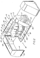
- the new automatic breadmaker 10 has a base or floor 11 and a compartment 13 atop the floor. Such compartment 13 encloses a controller 15 and a reversible electric motor 17.
- the controller 15 executes the operating cycle of the breadmaker 10 and as described in more detail below, the motor 17 powers kneading members which mix ingredients to make bread dough.
- An oven chamber 19 is atop the floor 11, abuts the compartment 13 and is formed by the floor 11, a wall member 21 and an access door 23 having a window 25 allowing the user to view kneading and baking operations.
- a pan 27 for receiving ingredients mixed to make bread dough is mounted in the chamber 19.
- the wall member 21 has a rear portion 29, a top portion 31 and lateral side portions 33, all of which are fixed, i.e., non-movable with respect to one another and to the floor 11.
- the surface 35 of the top portion 31 is at a first level 37 above the breadmaker floor 11 and the portions 31, 33 define a flat face which is substantially perpendicular.
- the wall member 21 also has a vertical lateral edge 41 and a horizontal top edge 43, the latter located substantially directly above the pan 27 and extending along the pan length.
- the access door 23 is hinged to the wall member 21 along the front lateral edge 41 of the wall member 21 and along a rear lateral edge 45 of the door 23 and is pivotable laterally about a substantially vertical axis 47.
- the access door 23 swings in a substantially horizontal direction and creates a front opening 49 extending substantially to the floor 11, to the region above the pan and to the side portions 33.
- the door 23 itself has a front surface 53 and a top surface 55, both of which are attractively curvilinear. There are also substantially flat first and second side surfaces 57, 59, respectively, the former having a substantially vertical rear edge 45. At least major portions of the top surface 55 and the first side surface 57 extend rearwardly from the front surface 53.
- the door 23 swings laterally for front opening without any door movement above the first level 37 and the resulting opening 49 extends substantially to the oven floor 11.
- the portions 55, 57, 59 also define a flat face 61 which is substantially perpendicular and which abuts the face 39 of the wall member 21 when the door 23 is closed for baking.
- the access door 23 When the access door 23 is closed, it extends upwardly from along the oven floor 11 and curves rearwardly to a position directly above the pan 27. That is, the top edge 63 of the door 23 abuts the top edge 43 of the wall member 21 directly above the pan 27.
- the breadmaker 10 has a very generous mouth area, open at the top as well as at the front and sides, so that insertion and removal of the pan 27 is further facilitated.
- a laterally-swinging door 23 has advantages over a top-hinged door (a door hinged along its top edge), especially where a breadmaker occupies a place on a kitchen counter beneath cupboards, as is frequently the case. Such a door 23 swings substantially horizontally and permits multi-directional access to the oven chamber 19 with the door 23 away from the front of the breadmaker 10. Counter-to-cupboard spacing can prevent a top-hinged door from being fully opened and/or from staying open.
- the laterally-swinging door 23 also has advantages over a bottom-hinged door since when open, the latter protrudes outward toward the user and may impair easy access to the oven chamber.
- FIGURE 2 It is apparent from FIGURE 2 that the oven floor 11 and the access door 23 are each longer than the pan 27.
- Such configuration accommodates "wide-side” insertion of the pan 27 into the chamber 19 and minimizes the height of the breadmaker 10.
- Wide-side means that the pan 27 can be inserted into the chamber 19 while holding the pan so that as shown in FIGURE 3, its long axis 65 is generally parallel to the rear portion 29 of the wall member 21. There is no need to twist or turn the pan 27 during pan placement and removal.
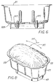
- the new pan 27 has a bottom 67 supported atop a "foot-like" downwardly-extending rim 69. When the pan 27 is in place in the chamber 19, such rim 69 rests on the oven floor 11.
- the pan 27 has first and second end panels 71 and 73, respectively, and first and second side panels 75 and 77, respectively.
- the panels 71, 73, 75 and 77 are substantially flat and extend upwardly from the bottom 67 at an angle thereto which is slightly greater than 90°.
- the pan 27 is thereby said to have "draft" so that the baked loaf can be easily removed therefrom by inverting the pan 27 .
- the junctions 79 of the panels 71, 73, 75, 77 with the bottom 67 and the junctions 81 of the panels 71, 73, 75, 77 with one another are slightly curved and serve to give a shape to the finished loaf which closely resembles that of a normal bakery loaf made in a commercial bakery.
- the top of the pan 27 is bounded by an outwardly-projecting lip 83 and a handle 85 juts from the lip 83 above each of the side panels 75 and 77. While the pan 27 may be grasped by the lip 83 anywhere around its perimeter, the handles 85 permit a more positive grasp which is of benefit when handling a hot pan 27 with insulated mitts, pads or the like.
- the bottom 67 has a pair of bosses 87 spaced along the length of the pan 27.
- Each boss 87 has a shaft aperture 89 formed in it and a bearing 91 is mounted in each aperture 89 to receive a shaft 93 with slight sliding clearance.
- Such shafts 93 are linked to the motor 17, extend through the pan bottom 67 and drive the kneading members 95a, 95b.
- the interior of the pan 27 includes a plurality of spaced-apart mixing ridges 97 extending generally between the bottom 67 and the lip 83.
- there are four ridges 97 i.e., a pair of ridges 97 for each kneading member 95.
- Each ridge 97 is linear in an up-down direction and has a generally semi-circular cross-sectional shape.
- each opposed pair of ridges e.g., ridges 97a and 97b as in FIGURE 3
- the pan 27 has a length L, a width W, an inside base area A (the area circumscribed by the overlay heavy dashed line 103) and a depth D.
- the ratio of length L to width W is greater than 1.5 and, most preferably, such ratio is greater than 1.8.
- the ratio of depth D to inside base area A is preferably less than about 0.1 and, most preferably, is less than about 0.08. (It is noted that D and A are linear and area measurements, respectively. The ratios use numerical values without regard to units of measure.)
- another feature of the new pan 27 is that right cross-sectional configurations of the pan 27, i.e., the pan size and shape as viewed in cross-section at planes 5-5 at right angles to the long axis 65 of the pan 27 and at spaced locations along the pan length, are substantially constant. This feature also contributes to the fact that the loaf produced by the new breadmaker 10 has the appearance of a normal bakery loaf.
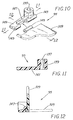
- a second embodiment of the pan 27 includes a pan bottom 105 having a pair of recessed portions 107, each receiving one of the kneading members 95 described below.
- each recessed portion 107 is of sufficient depth to fully receive the collapsed blade 109 of the kneading member 95. That is, when a blade 109 is folded flat as shown in dashed outline in FIGURE 12, such blade 109 is "nested" in a recessed portion 107.
- such floor 11 has a floor length FL and a floor width FW.
- the preferred ratio of floor length FL to floor width FW is at least about 1.5 and most preferably, such ratio is at least about 1.8.
- the breadmaker 10 and its pan 27 produce a loaf of bread 111 in the configuration of a normal bakery loaf. That is, the loaf 111 has substantially flat ends and sides and a risen topside 113 extending along its length. As is characteristic of a normal bakery loaf, the loaf produced by the breadmaker is "crowned" or curved in two mutually-perpendicular planes as represented by the arrows 115 and 117.
- the motor is coupled to means 119 for driving such members 95 and has a smaller-diameter driving pulley 121 attached to and rotating with the motor shaft.
- Such pulley 121 is linked by a belt 123 to a larger-diameter driven pulley 125 which rotates at a speed well below that of the pulley 121.
- a first intermediate-diameter gear 127 is mounted on and concentric with the pulley 125 and, of course, rotates at the same speed as the pulley 125.
- the first gear 127 engages a second gear 129 which is also of intermediate diameter equal to that of the first gear 127. From the foregoing, it is apparent that for either direction of motor rotation, the gears 127, 129 rotate in opposite directions at the same speed.
- the shaft 93a driving one of the kneading members 95a is concentric with the gear 129 and the shaft 93b driving the other kneading member 95b is concentric with the pulley 125 and gear 127.
- the shafts 93a, 93b are substantially parallel to one another and both shafts 93 rotate at the same speed which, of course, is much lower than the shaft speed of the motor 17.
- Each kneading member 95 has a hub 135 with an opening 137 therethrough sized and shaped to fit its respective drive shaft 93 with slight sliding clearance.
- the opening 137 may be in the shape of the letter D or may have any other torque-transmitting shape, e.g., square or hexagon.
- the hub 135 includes a grip member 139 to facilitate finger grasping and attachment of the kneading member 95 after the pan 27 is placed in the breadmaker 10 reparatory to ingredient mixing, dough kneading and baking.
- Each kneading member 95 includes a lower arm 141 extending radially outward from the hub 135 and having a kneading blade 109 pivotably pinned to it.
- the arm 141 has a pair of radially-spaced tube-like portions 143 between which is received the portion 145 of the blade 109.
- the portions 143 and 145 are coupled together by a pin (not shown).
- the arm 141 also has an abutment member 147 supporting the blade 109 at its upright position.
- its blade 109 stands upright for mixing or kneading (and is supported there by the abutment member 147) or collapses by folding down for baking.
- the kneading members 95a, 95b are "mirror images" of one another so that the blades 109 of both are simultaneously upright or collapsed, notwithstanding that such kneading members 95a, 95b are being driven in opposite directions.
- the arm 14 has an edge surface 149 angled downward toward the pan bottom 67 and outward away from the portions 143, 145.
- edge surface 149 angled downward toward the pan bottom 67 and outward away from the portions 143, 145.
- the member 95 is rotated in a direction which collapses the blade 109 as shown in dashed outline in FIGURE 12, such surface 149 is of some help in urging dough ingredients, i.e., flour or the like, up away from the pan bottom 67. Better ingredient mixing results.
- the kneading members 95a, 95b are spaced along the length of the pan 27 so that dough in the pan 27 will be reached by one or both of such members 95a, 95b.
- the pan 27 is placed (by "wide-side" insertion) into the oven chamber 19 and placement is so that the bottom support rim 69 of the pan 27 is between a pair of retention barriers 151 projecting upward from the floor 11.
- the barriers 151 and the support rim 69 are generally conformably shaped to one another so that the pan 27 is prevented by the barriers 151 from moving a significant distance in any direction.
- a holding latch 153 is mounted on the floor 11 and has a tongue that projects into a slot in the pan rim 69.
- the latch 153 is spring-biased toward the rim 69 for pan holding during mixing and baking and is released by finger pressure at the conclusion of baking.
- the kneading members 95a, 95b are mounted on their respective shafts 93a, 93b and the ingredients then added to the pan 27.
- the operating cycle is initiated and the motor 17 is operated in what is arbitrarily identified as the first or forward direction. So operated, the kneading members 95a and 95b counter-revolve, i.e., they are driven clockwise and counterclockwise, respectively, for several minutes to mix ingredients. During that time, the blades 109 are upright.
- the motor 17 is operated in the second or reverse direction for a time during which the kneading members 95a, 95b also counter-revolve and the blades 109 are collapsed. It has been found that brief reversal tends to pick up unmixed flour from the region 155 of the pan 27 that would not otherwise be properly mixed. Thereafter, the motor 17 is again operated in the forward direction and, finally, is operated in the reverse direction for a few seconds to collapse the blades 109 prior to baking.
- the door 23 is opened horizontally and the pan 27 removed in the same manner in which it was placed in the chamber 19, i.e., by "wide side” removal.
- the resulting loaf 111 is of normal bakery loaf configuration and has a risen topside 113 extending along its length.
Landscapes
- Life Sciences & Earth Sciences (AREA)
- Engineering & Computer Science (AREA)
- Food Science & Technology (AREA)
- Baking, Grill, Roasting (AREA)
- Bakery Products And Manufacturing Methods Therefor (AREA)
- Refrigerator Housings (AREA)
Claims (10)
- Automatische Brotbackvorrichtung (10) der Bauart, die aufweist: einen Antriebsmechanismus (119); eine Ofenkammer (19), die durch einen Boden (11) sowie durch oben, vom und seitlich umschließende Flächen gebildet wird, wobei sich die Oberseite in einer ersten Höhe (37) oberhalb des Bodens (11) befindet; eine Zugangstür (23), die zumindest eine der umschließenden Flächen beinhaltet; und eine Mulde (27) in der Ofenkammer (19) mit einem darin befindlichen Knetelement (95), welches mit dem Antriebsmechanismus (119) gekoppelt ist, dadurch gekennzeichnet, daß:die Zugangstür (23) die Vorderseite (53) und zumindest den größeren Teil jeweils von der Oberseite (35, 55) und einer ersten Seitenfläche (57) beinhaltet, von denen sich jede nach hinten von der Vorderseite (53) aus erstreckt, wobei die erste Seitenfläche (57) eine im wesentlichen vertikale hintere Kante (45) aufweist; unddie Zugangstür (23) entlang ihrer hinteren Kante (45) aufgehängt ist, um sich vorn zu öffnen, ohne daß irgendeine Bewegung der Tür oberhalb der ersten Höhe (37) erfolgt;wobei die Zugangstür (23) in seitlicher Richtung schwenken kann, um einen Zugang von mehreren Richtungen zur Ofenkammer (19) zu ermöglichen, wobei sich die Zugangstür (23) von der Vorderseite der Backvorrichtung (10) weg befindet.
- Automatische Brotbackvorrichtung (10) nach Anspruch 1, dadurch gekennzeichnet, daßdie Mulde (27) einen Boden (67) aufweist, der länger ist als breit; undder Boden (11) des Ofens und die Zugangstür (23) jeweils breiter sind als die Länge der Mulde (27) beträgt, um ein breitseitiges Einsetzen der Mulde (27) in die Ofenkammer (19) zu ermöglichen;wodurch die Höhe der Brotbackvorrichtung (10) minimiert wird.
- Automatische Brotbackvorrichtung nach Anspruch 1, dadurch gekennzeichnet, daß sich die Zugangstür (23), wenn sie geschlossen ist, entlang des Bodens (11) des Ofens und davon nach oben und nach hinten bis zu einer Position unmittelbar oberhalb der Mulde (27) erstreckt, wobei ein Einsetzen und Herausnehmen der Mulde (27), wenn die Zugangstür (23) offen ist, weiter erleichtert wird.
- Automatische Brotbackvorrichtung (10) nach Anspruch 2, dadurch gekennzeichnet, daß die Mulde (27) ein darin befindliches, einen gegenseitigen Abstand aufweisendes Paar von Knetelementen (25) aufweist, wodurch die automatische Zubereitung eines Brotlaibs (111) erleichtert wird, der eine angehobene Oberseite (113) aufweist, die sich über seine Länge erstreckt.
- Automatische Brotbackvorrichtung (10) nach Anspruch 4, dadurch gekennzeichnet, daß das Paar Knetelemente (95) entlang der Länge der Mulde (27) einen gegenseitigen Abstand aufweist, wodurch Teig in der Mulde (27) von einem oder von beiden Knetelementen (95) erreicht wird.
- Automatische Brotbackvorrichtung nach Anspruch 1, dadurch gekennzeichnet, daß die Zugangstür (23) in einer im wesentlichen horizontalen Richtung geschwenkt werden kann, um die Ofenkammer (19) zu öffnen.
- Automatische Brotbackvorrichtung (10) der Bauart, die einen Boden (11) aufweist, einen Motor (17), der in Bezug darauf befestigt ist, eine Ofenkammer (19), die durch den Boden (11), feststehende umschließende Flächen (29, 31, 33) und eine Zugangstür (23) gebildet wird, und eine Mulde (27) in der Ofenkammer (19), die ein darin befindliches, von dem Motor angetriebenes Knetelement (95) aufweist, welches mit einem mit dem Motor gekoppelten Antriebsmechanismus (119) am Boden (11) der Ofenkammer in Eingriff gebracht werden kann, dadurch gekennzeichnet, daßeine der umschließenden Flächen (35) ein oberer Abschnitt (31) in einer Höhe (37) oberhalb des Bodens (11) ist, wobei sich der Boden (11) über den oberen Abschnitt (31) hinaus erstreckt;die Zugangstür (23) in seitlicher Richtung schwenkt, um die Ofenkammer (19) vorn zu öffnen, so daß eine Öffnung (49) gebildet wird, die sich im wesentlichen bis zum Boden (11) des Ofens erstreckt, um so das Einsetzen und Herausnehmen der Mulde (27) zu erleichtern.
- Automatische Bodenvorrichtung (10) nach Anspruch 7, dadurch gekennzeichnet, daß sich die Zugangstür (23), wenn sie geschlossen ist, entlang des Bodens (11) des Ofens und davon nach oben und nach hinten bis zu einer Position unmittelbar oberhalb der Mulde (27) erstreckt, wobei ein Einsetzen und Herausnehmen der Mulde (27), wenn die Zugangstür (23) offen ist, weiter erleichtert wird.
- Automatische Brotbackvorrichtung (10) nach Anspruch 7, dadurch gekennzeichnet, daß das Paar Knetelemente (95) entlang der Länge der Mulde (27) einen gegenseitigen Abstand aufweist, wodurch Teig in der Mulde (27) von einem oder von beiden Knetelementen (95) erreicht wird.
- Automatische Brotbackvorrichtung (10) nach Anspruch 7, dadurch gekennzeichnet, daß:eine der umschließenden Flächen (35) ein Wandelement (21) beinhaltet, welches eine vordere seitliche Kante (41) aufweist;der Boden (11) eine vordere Kante vor der vorderen seitlichen Kante (41) des Wandelements (41) aufweist; unddie Zugangstür (23) an der vorderen seitlichen Kante (41) aufgehängt ist.
Applications Claiming Priority (2)
| Application Number | Priority Date | Filing Date | Title |
|---|---|---|---|
| US328507 | 1994-10-25 | ||
| US08/328,507 US5493955A (en) | 1994-10-25 | 1994-10-25 | Automatic breadmaker with laterally-opening wide door |
Publications (2)
| Publication Number | Publication Date |
|---|---|
| EP0709026A1 EP0709026A1 (de) | 1996-05-01 |
| EP0709026B1 true EP0709026B1 (de) | 1999-06-16 |
Family
ID=23281272
Family Applications (1)
| Application Number | Title | Priority Date | Filing Date |
|---|---|---|---|
| EP95113501A Expired - Lifetime EP0709026B1 (de) | 1994-10-25 | 1995-08-28 | Automatische Brotbackmaschine mit seitlich schwenkbarer Tür |
Country Status (6)
| Country | Link |
|---|---|
| US (1) | US5493955A (de) |
| EP (1) | EP0709026B1 (de) |
| JP (1) | JP2758867B2 (de) |
| CN (1) | CN1122677A (de) |
| AT (1) | ATE181208T1 (de) |
| DE (1) | DE69510296T2 (de) |
Families Citing this family (25)
| Publication number | Priority date | Publication date | Assignee | Title |
|---|---|---|---|---|
| US5694832A (en) * | 1995-01-06 | 1997-12-09 | Matsushita Electric Industrial Co., Ltd. | Automatic bread producing machine |
| CN2257692Y (zh) * | 1996-09-09 | 1997-07-16 | 王冬雷 | 具有烤箱功能的自动面包机 |
| US5860357A (en) * | 1997-02-24 | 1999-01-19 | Chiaphus Industries, Limited | Breadmaker |
| US5771784A (en) * | 1997-07-28 | 1998-06-30 | Pentalpha Enterprises Ltd. | Paddle for bread-making machine |
| US5901637A (en) * | 1998-04-06 | 1999-05-11 | Appliance Development Corporation | Combined baking oven and automatic bread baking apparatus |
| KR20030059981A (ko) * | 2002-01-05 | 2003-07-12 | 주식회사 카이젤 | 토스터 제빵기 |
| KR20040096136A (ko) * | 2003-05-07 | 2004-11-16 | 삼성전자주식회사 | 제빵기 |
| US20060191536A1 (en) * | 2005-02-25 | 2006-08-31 | Allied Healthcare Products, Inc. | Bag mask resuscitator |
| CN201223311Y (zh) * | 2008-06-20 | 2009-04-22 | 厦门灿坤实业股份有限公司 | 一种侧开门的制面包机 |
| CN102144897B (zh) * | 2010-02-05 | 2014-05-28 | 漳州灿坤实业有限公司 | 自制面包的方法、面包机和面包配料盒 |
| US8720325B2 (en) | 2010-04-29 | 2014-05-13 | Whirlpool Corporation | Food processor with a lockable adjustable blade assembly |
| US10449685B2 (en) | 2010-04-29 | 2019-10-22 | Whirlpool Corporation | Food processor with adjustable blade assembly |
| USD673810S1 (en) * | 2011-05-18 | 2013-01-08 | Zojirushi Corporation | Bread case for bread machine |
| CN103815797B (zh) * | 2012-11-19 | 2016-03-23 | 美的集团股份有限公司 | 烤箱 |
| US9237825B2 (en) * | 2013-03-01 | 2016-01-19 | Whirlpool Corporation | Cooking vessel for a cooking and mixing appliance kit |
| US9241595B2 (en) * | 2013-03-01 | 2016-01-26 | Whirlpool Corporation | Cooking and mixing appliance kit |
| US20140245900A1 (en) * | 2013-03-01 | 2014-09-04 | Whirlpool Corporation | Mixing tool set for a cooking and mixing appliance kit |
| US20140245902A1 (en) * | 2013-03-01 | 2014-09-04 | Whirlpool Corporation | Mixing mechanism for a cooking and mixing appliance kit |
| US9808774B2 (en) | 2013-03-01 | 2017-11-07 | Whirlpool Corporation | Stirring wand |
| GB2515737A (en) * | 2013-07-01 | 2015-01-07 | Kenwood Ltd | Bread-making kitchen appliance |
| US10085599B2 (en) | 2014-12-19 | 2018-10-02 | Whirlpool Corporation | Multi-cook and food processing prep product |
| EP3085285B1 (de) * | 2015-04-23 | 2019-06-12 | Whirlpool Corporation | Kochsystem, insbesondere für nudel, reis und brot |
| USD853782S1 (en) | 2017-02-20 | 2019-07-16 | Whirlpool Corporation | Food processor |
| USD867051S1 (en) | 2017-10-04 | 2019-11-19 | Whirlpool Corporation | Grinder attachment for a stand mixer |
| USD885822S1 (en) | 2018-12-14 | 2020-06-02 | Whirlpool Corporation | Food grinder |
Family Cites Families (21)
| Publication number | Priority date | Publication date | Assignee | Title |
|---|---|---|---|---|
| US2478253A (en) * | 1942-12-02 | 1949-08-09 | Libbey Owens Ford Glass Co | Combination oven unit |
| US2415711A (en) * | 1943-05-03 | 1947-02-11 | Quik Seal Inc | Refrigerated dough mixer |
| US2502685A (en) * | 1946-11-25 | 1950-04-04 | Henry T Warner | Barbecue apparatus |
| US2622760A (en) * | 1949-11-28 | 1952-12-23 | Vera D Kissig | Closure for opened ends of wrapped bread loaves |
| US3065326A (en) * | 1960-12-14 | 1962-11-20 | Dominion Electric Corp | Electrically heated cooking device |
| GB2070907B (en) * | 1979-07-27 | 1984-05-10 | Matsushita Electric Industrial Co Ltd | Heating cooking device |
| US4538509A (en) * | 1983-08-22 | 1985-09-03 | Hosiden Electronics Co., Ltd. | Automatic bread baking machine |
| US4762057A (en) * | 1985-10-11 | 1988-08-09 | Matsushita Electric Industrial Co., Ltd. | Automatic bread producing machine |
| CA1277548C (en) * | 1985-10-12 | 1990-12-11 | Ojima, Tadasu | Method of and an apparatus for making bread at home |
| JPS6358571A (ja) * | 1986-08-29 | 1988-03-14 | Omron Tateisi Electronics Co | 航空旅客管理システム |
| JPH0415158Y2 (de) | 1987-03-11 | 1992-04-06 | ||
| US4903587A (en) | 1987-04-02 | 1990-02-27 | Hitachi Heating Appliances Co., Ltd. | Automatic baking apparatus |
| JPS63296711A (ja) * | 1987-05-29 | 1988-12-02 | 松下電器産業株式会社 | パン製造機 |
| USD305856S (en) | 1987-06-09 | 1990-02-06 | Sharp Corporation | Microwave oven |
| JPH0162727U (de) | 1987-10-15 | 1989-04-21 | ||
| DE3886187T2 (de) * | 1987-12-28 | 1994-04-07 | Matsushita Electric Ind Co Ltd | Verfahren zum Installieren eines Backtroges in einem Ofen und Vorrichtung zur Ausführung des Verfahrens. |
| US4977822A (en) | 1988-05-09 | 1990-12-18 | Samsung Electronics Co., Ltd. | Kneading means of a home automatic bread baking device |
| JP2517069B2 (ja) * | 1988-06-08 | 1996-07-24 | 松下電器産業株式会社 | 自動製パン機 |
| KR910001223B1 (ko) * | 1988-08-29 | 1991-02-26 | 삼성전자 주식회사 | 제빵기의 요구르트 제조장치 및 방법 |
| US4984512A (en) * | 1989-10-11 | 1991-01-15 | Zojirushi Corporation | Automatic bread-making device |
| JPH0428508U (de) * | 1990-06-29 | 1992-03-06 |
-
1994
- 1994-10-25 US US08/328,507 patent/US5493955A/en not_active Expired - Fee Related
-
1995
- 1995-08-28 EP EP95113501A patent/EP0709026B1/de not_active Expired - Lifetime
- 1995-08-28 AT AT95113501T patent/ATE181208T1/de not_active IP Right Cessation
- 1995-08-28 DE DE69510296T patent/DE69510296T2/de not_active Expired - Fee Related
- 1995-10-23 CN CN95115961A patent/CN1122677A/zh active Pending
- 1995-10-25 JP JP7277964A patent/JP2758867B2/ja not_active Expired - Lifetime
Also Published As
| Publication number | Publication date |
|---|---|
| DE69510296D1 (de) | 1999-07-22 |
| JP2758867B2 (ja) | 1998-05-28 |
| CN1122677A (zh) | 1996-05-22 |
| US5493955A (en) | 1996-02-27 |
| EP0709026A1 (de) | 1996-05-01 |
| MX9504169A (es) | 1997-07-31 |
| ATE181208T1 (de) | 1999-07-15 |
| JPH08224173A (ja) | 1996-09-03 |
| DE69510296T2 (de) | 1999-10-14 |
Similar Documents
| Publication | Publication Date | Title |
|---|---|---|
| CA2158316C (en) | Automatic breadmaker with laterally-opening wide door | |
| EP0709026B1 (de) | Automatische Brotbackmaschine mit seitlich schwenkbarer Tür | |
| US5778766A (en) | Automatic breadmaker having toaster oven function | |
| US5839356A (en) | Automatic bread making machine | |
| US5460506A (en) | Home pasta maker | |
| US4176971A (en) | Multi-purpose kitchen appliance | |
| US5324185A (en) | Pasta, pastry, cookie, and hors d'oeuvre maker | |
| EP0780080B1 (de) | Reibe für Nahrungsmittel | |
| US5445061A (en) | Combination bread making machine and cooker | |
| US4176593A (en) | Cooking device | |
| WO2003057355A1 (en) | Food preparation system | |
| US5903981A (en) | Pizza cutting and serving tool | |
| EP0709024A1 (de) | Automatische Vorrichtung zur Herstellung von Brot mit breitem Backblech | |
| CA2254509A1 (en) | Automatic breadmaker with plural kneading members | |
| US5568764A (en) | Automatic breadmaker with interior lamp | |
| MXPA95004169A (en) | Automatic breading machine with door ampliade late opening | |
| MXPA95004171A (en) | Automatic breading machine with multiplesmembers of amas | |
| MXPA95004170A (en) | Automatic breadmaker with wide-loaf pan | |
| Cheng | FOOD MACHINERY CL | |
| JP2700893B2 (ja) | 自動製パン機 | |
| WO2025257532A1 (en) | Food processing apparatus | |
| EP1474979B1 (de) | Brotbackgerät | |
| KR100364363B1 (ko) | 음식물 교반기 | |
| JPH02207735A (ja) | パン製造機 | |
| KR20240165221A (ko) | 반죽 자동 성형장치 |
Legal Events
| Date | Code | Title | Description |
|---|---|---|---|
| PUAI | Public reference made under article 153(3) epc to a published international application that has entered the european phase |
Free format text: ORIGINAL CODE: 0009012 |
|
| 17P | Request for examination filed |
Effective date: 19960111 |
|
| AK | Designated contracting states |
Kind code of ref document: A1 Designated state(s): AT BE DE DK ES FR GB IT LU NL SE |
|
| GRAG | Despatch of communication of intention to grant |
Free format text: ORIGINAL CODE: EPIDOS AGRA |
|
| 17Q | First examination report despatched |
Effective date: 19980817 |
|
| GRAG | Despatch of communication of intention to grant |
Free format text: ORIGINAL CODE: EPIDOS AGRA |
|
| GRAH | Despatch of communication of intention to grant a patent |
Free format text: ORIGINAL CODE: EPIDOS IGRA |
|
| GRAH | Despatch of communication of intention to grant a patent |
Free format text: ORIGINAL CODE: EPIDOS IGRA |
|
| GRAA | (expected) grant |
Free format text: ORIGINAL CODE: 0009210 |
|
| AK | Designated contracting states |
Kind code of ref document: B1 Designated state(s): AT BE DE DK ES FR GB IT LU NL SE |
|
| PG25 | Lapsed in a contracting state [announced via postgrant information from national office to epo] |
Ref country code: SE Free format text: THE PATENT HAS BEEN ANNULLED BY A DECISION OF A NATIONAL AUTHORITY Effective date: 19990616 Ref country code: NL Free format text: LAPSE BECAUSE OF FAILURE TO SUBMIT A TRANSLATION OF THE DESCRIPTION OR TO PAY THE FEE WITHIN THE PRESCRIBED TIME-LIMIT Effective date: 19990616 Ref country code: IT Free format text: LAPSE BECAUSE OF FAILURE TO SUBMIT A TRANSLATION OF THE DESCRIPTION OR TO PAY THE FEE WITHIN THE PRESCRIBED TIME-LIMIT;WARNING: LAPSES OF ITALIAN PATENTS WITH EFFECTIVE DATE BEFORE 2007 MAY HAVE OCCURRED AT ANY TIME BEFORE 2007. THE CORRECT EFFECTIVE DATE MAY BE DIFFERENT FROM THE ONE RECORDED. Effective date: 19990616 Ref country code: ES Free format text: THE PATENT HAS BEEN ANNULLED BY A DECISION OF A NATIONAL AUTHORITY Effective date: 19990616 |
|
| REF | Corresponds to: |
Ref document number: 181208 Country of ref document: AT Date of ref document: 19990715 Kind code of ref document: T |
|
| ET | Fr: translation filed | ||
| REF | Corresponds to: |
Ref document number: 69510296 Country of ref document: DE Date of ref document: 19990722 |
|
| PG25 | Lapsed in a contracting state [announced via postgrant information from national office to epo] |
Ref country code: LU Free format text: LAPSE BECAUSE OF NON-PAYMENT OF DUE FEES Effective date: 19990828 Ref country code: AT Free format text: LAPSE BECAUSE OF NON-PAYMENT OF DUE FEES Effective date: 19990828 |
|
| PG25 | Lapsed in a contracting state [announced via postgrant information from national office to epo] |
Ref country code: BE Free format text: LAPSE BECAUSE OF NON-PAYMENT OF DUE FEES Effective date: 19990831 |
|
| PG25 | Lapsed in a contracting state [announced via postgrant information from national office to epo] |
Ref country code: GB Free format text: LAPSE BECAUSE OF NON-PAYMENT OF DUE FEES Effective date: 19990916 Ref country code: DK Free format text: LAPSE BECAUSE OF FAILURE TO SUBMIT A TRANSLATION OF THE DESCRIPTION OR TO PAY THE FEE WITHIN THE PRESCRIBED TIME-LIMIT Effective date: 19990916 |
|
| NLV1 | Nl: lapsed or annulled due to failure to fulfill the requirements of art. 29p and 29m of the patents act | ||
| BERE | Be: lapsed |
Owner name: THE WEST BEND CY Effective date: 19990831 |
|
| PLBE | No opposition filed within time limit |
Free format text: ORIGINAL CODE: 0009261 |
|
| STAA | Information on the status of an ep patent application or granted ep patent |
Free format text: STATUS: NO OPPOSITION FILED WITHIN TIME LIMIT |
|
| GBPC | Gb: european patent ceased through non-payment of renewal fee |
Effective date: 19990916 |
|
| 26N | No opposition filed | ||
| PGFP | Annual fee paid to national office [announced via postgrant information from national office to epo] |
Ref country code: FR Payment date: 20010801 Year of fee payment: 7 |
|
| PGFP | Annual fee paid to national office [announced via postgrant information from national office to epo] |
Ref country code: DE Payment date: 20030228 Year of fee payment: 8 |
|
| PG25 | Lapsed in a contracting state [announced via postgrant information from national office to epo] |
Ref country code: FR Free format text: LAPSE BECAUSE OF NON-PAYMENT OF DUE FEES Effective date: 20030430 |
|
| REG | Reference to a national code |
Ref country code: FR Ref legal event code: ST |
|
| PG25 | Lapsed in a contracting state [announced via postgrant information from national office to epo] |
Ref country code: DE Free format text: LAPSE BECAUSE OF NON-PAYMENT OF DUE FEES Effective date: 20040302 |