EP0709046A2 - Offener Schaukasten - Google Patents
Offener Schaukasten Download PDFInfo
- Publication number
- EP0709046A2 EP0709046A2 EP95116591A EP95116591A EP0709046A2 EP 0709046 A2 EP0709046 A2 EP 0709046A2 EP 95116591 A EP95116591 A EP 95116591A EP 95116591 A EP95116591 A EP 95116591A EP 0709046 A2 EP0709046 A2 EP 0709046A2
- Authority
- EP
- European Patent Office
- Prior art keywords
- storage compartment
- suction port
- compartment side
- discharge port
- flowpath
- Prior art date
- Legal status (The legal status is an assumption and is not a legal conclusion. Google has not performed a legal analysis and makes no representation as to the accuracy of the status listed.)
- Granted
Links
Images


Classifications
-
- A—HUMAN NECESSITIES
- A47—FURNITURE; DOMESTIC ARTICLES OR APPLIANCES; COFFEE MILLS; SPICE MILLS; SUCTION CLEANERS IN GENERAL
- A47F—SPECIAL FURNITURE, FITTINGS, OR ACCESSORIES FOR SHOPS, STOREHOUSES, BARS, RESTAURANTS OR THE LIKE; PAYING COUNTERS
- A47F3/00—Show cases or show cabinets
- A47F3/04—Show cases or show cabinets air-conditioned, refrigerated
- A47F3/0439—Cases or cabinets of the open type
- A47F3/0443—Cases or cabinets of the open type with forced air circulation
- A47F3/0447—Cases or cabinets of the open type with forced air circulation with air curtains
Definitions
- the present invention relates to an open showcase having a storage compartment in which commercial products are displayed and an aperture formed in the front surface thereof which, this aperture, is closed by a multi-layered air curtain.
- the open showcase of this kind is described in, for example, Japanese Patent Publication No. 61-60353 (F25D17/08) and so on.
- This open showcase is displaying frozen foods or the like from inside the storage compartment. Since the temperature inside the storage compartment is low, one layer of air curtain may not be sufficient to maintain the cold air in the storage compartment. Therefore, a multi-layered air curtain is used to maintain the cold air in the storage compartment. Further, the front panel is made with a heat insulation material. This front panel prevents customers from looking into the storage compartment.
- open showcases displaying refrigerated products use one layer of air curtain to maintain the cold air in the storage compartment, some of which are equipped with a front glass on the front surface thereof.
- the inner air curtain is significantly low temperature (for example -18°C).
- the outer air curtain is, however, higher in temperature (for example +10°C) than it.
- the transparent panel disposed further away from the outer air curtain is also affected by the due formation, and the situation of the dew formation is much different from the dew formation in the flat showcases. Therefore, simple application of the heating mechanism in the flat showcases causes low heating efficiency, and thus the power consumption for heating is increased.
- the present invention is attempting to solve the foregoing problem and is directed to provide an open showcase in which a front aperture is closed with a multi-layered air curtain and dew formation on a transparent front panel can be avoided efficiently.
- an open showcase (1) comprises an outer housing (3) having an aperture (8) in the front surface thereof; an outer suction port (23) formed at the lower end of this outer housing on the storage compartment side; an inner suction port (38) formed on the storage compartment side from this outer suction port; an outer discharge port (24) formed at the upper part of said outer housing on the storage compartment side; an inner discharge port (39) formed on the storage compartment side from this outer discharge port; an outer flowpath (21) connecting said outer suction port and said outer discharge port; an inner flowpath (36) connecting said inner suction port and said inner discharge port; a blower (26) disposed in said outer flowpath; and a evaporator (41) and a blower (40) disposed in said inner flowpath
- a front panel (9) formed of laminate-structured transparent panels (66, 67) is extended upward from the lower end of said outer housing, and a heat source (68) is provided on the transparent panel (67) of this front panel on the storage compartment side.
- a light source (11) is provided on the surface of the front panel on the storage compartment side at the bottom end thereof or the surface on the storage compartment side at the lower end of said outer housing.
- a transparent diaphragm (17) is removably provided between the inner suction port and said outer suction port.
- the lowermost end of this diaphragm may be located at the generally same height as said light source or lower than said light source.
- a transparent diaphragm is provided between said inner suction port and said outer suction port, and the uppermost end of this diaphragm may be formed lower than the uppermost end of said front panel.
- a fall preventing member (47) is extended upward from the storage compartment side of said inner suction port, and the uppermost end of this fall preventing member may be higher than the uppermost end of said diaphragm.
- a low temperature air curtain is formed in front of the open showcase. Further, the second air curtain covers this low temperature air curtain, protecting the low temperature air curtain.
- This open showcase is equipped with the transparent front panel, and a transparent panel on the storage compartment side is heated by the heat source so that the transparent panel on the storage compartment side of the front panel will not cause dew formation.
- a light source for illuminating the storage compartment and so on is disposed near the lower part of the front panel, and the side of the front panel on the storage compartment is heated by the heat produced from the light source.
- the lowermost end of the diaphragm is located at a position generally corresponding to that of the light source, so that the light source can easily be replaced by means of removing the diaphragm.
- the low temperature air curtain is mixed with the second air curtain at the boarder of it.
- the temperature of the boarder part becomes almost uniform, and the almost uniformed air flow at the boarder part contacts with the diaphragm.
- Fig. 1 is a vertical cross-sectional view of the open showcase according to the first embodiment of the present invention.
- Fig. 2 is an expanded view of the essentials in Fig. 1.
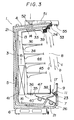
- Fig. 3 is a vertical cross-sectional view of the open showcase according to the second embodiment.
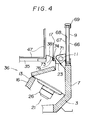
- Fig. 4 is an expanded view of the essentials in Fig. 2.
- Fig. 1 is a vertical cross-sectional view of an open showcase according to the first embodiment of the present invention.
- Fig. 2 is an expanded view of the essentials in Fig. 1.
- an outer housing 3 of a multi-stage open showcase 1 for displaying various products such as frozen foods is a heat insulated housing made of a heat insulation material, and constructed by a top wall 4, a back wall 5, a bottom wall 6, a front wall 7, and a pair of left and right side walls which are not shown, and an aperture 8 for bringing in and taking out products is formed in the front surface thereof.
- a front glass 9, which is a transparent front panel is provided elongately across from right to left.
- a florescent light 11 which is a light source, is disposed.
- a top wall 14, a back wall 15, and a bottom wall 16 of an inner housing 13 are positioned at a proper distance from the top wall 4, the back wall 5, the bottom wall 6, and the front wall 7 of this outer housing 3.
- This inner housing 13 is, as in the outer housing 3, a heat insulating housing made of a heat insulating material. Both right and left sides of the inner housing 13 are closed with a pair of side walls of the outer housing 3. Further, at the front end of the bottom wall 16, a transparent diaphragm 17 such as glass is provided elongately across from right to left. Further, the distance between the outer housing 3 and the inner housing 13 defines an outer flowpath 21. An outer suction port 23 and an outer discharge port 24 are formed at the lower end of this outer flowpath 21 and at the upper end thereof, respectively. In lower part of the outer flowpath 21, a blower 26 is disposed.
- a partition top panel 33, a partition back wall panel 34, and a partition floor panel 35 are positioned.
- the distance between the partition top panel 33, the partition back wall panel 34, and the partition floor panel 35 and the inner housing 13 defines an inner flowpath 36.
- An inner suction port 38 and an inner discharge port 39 are formed at the lower end of this inner flowpath 36 and at the upper end thereof, respectively.
- a blower 40 and a evaporator 41 are positioned in the inner flowpath 36 downward from the partition floor panel 35 and in the inner flowpath 36 in back of the partition back wall panel 34, respectively.
- a plurality of product-displaying racks 45 are positioned at upper-to-lower multi-stages supported by a pair of right and left brackets of which height is adjustable.
- a wire rack 47 of an L-shape in cross section is mounted on the partition floor panel 35, and the front vertical part of this wire rack 47 is positioned over the right and left directions on the storage compartment side of the inner suction port 38, having a fall prevention function to prevent a product from falling on the upper surface of the inner suction port 38.
- a duct 51 is disposed on the upper surface of the top wall 4 of the outer housing 3.
- a blower 52 is disposed in this duct 51, blowing out air from a third discharge port 53 formed at the front end of the duct 51.
- a light source 55 such as florescent light is provided in front of this third discharge port 53 to illuminate the display chamber 44.
- the front glass 9 is formed of glass panels 66 and 67, which is a double-structured transparent panel.
- a conductive type heat reflection film or a heater 68 which serves as a heat source is extended on and along the inner surface of the glass plate 67 on the storage compartment side.
- the inner surface of the glass panel 66 facing outside of the storage compartment is provided with no heat source such as the heater 68 and is exposed to the space inside the front glass 9.
- a hand rail 69 is disposed at the top end of the front glass 9.
- a frosted florescent light cover 71 is provided to cover the fluorescent light 11.
- This florescent light cover 71 extends in the right-to-left direction in front side of the outer suction port 23. Meanwhile, the outer suction port 23 is formed between the outer housing 3 and the inner housing 13, but is formed angled to the side of the inner housing 13 rather than being formed across the whole space between the outer housing 3 and the inner housing 13.
- a step portion is formed and a locking member 74 of a triangle shape in cross section is attached elongately across from right to left.
- an engagement slot serving as a long and slender engaging part is formed between the step part of the panel member 73 and the locking member 74.
- the partition panel 17 is removably engaged with and supported in this engagement slot.
- a heater 76 as the heat source is provided on and along the inner surface of the panel member 73.
- the air in the inner flowpath 36 is blown in the direction indicated by the arrow and forcefully circulated.
- the air blown from the blower 40 moves toward the evaporator 41 and cooled, and then goes up and discharged out to the display chamber 44 through the inner discharge port 39.
- the cold air blown out from the inner discharge port 39 forms the inner layer air curtain a at the front panel of storage chamber 44, i.e., at the aperture 8 for bringing in and taking out products and cools inside of the display chamber 44.
- the air after cooling the inside of the display chamber 44 is sucked by the inner suction port 38 and returned to the blower 40.
- This inner layer air curtain a closes the display chamber 44, and prevents the cold air in the display chamber 44 from flowing out of the storage compartment.
- the inner air curtain a at, for example, approximately -18°C is protected by the double air curtains b and c .
- the outer layer air curtain c is formed of the outside air sucked by the blower 52, it is at the outside air temperature of, for example, approximately +27°C.
- the intermediate layer air curtain b is the forceful circulation of the generally same air caused by the blower 26 but becomes at approximately +10°C, cooled by the inner layer air curtain a and so forth. Therefore, the front glass 9 is exposed to the intermediate layer air curtain b at a temperature of +10°C and the outer layer air curtain c at a temperature of +27°C, and is thus in a temperature of from +10°C to +27°C. At the temperature of this level, no dew is formed normally.
- the surface of the front glass 9 on the storage compartment side is cooled. More specifically, the glass pane 67 on the storage compartment side becomes lower in temperature because the front glass 9 is the double-structured glass panes and the intermediate layer air curtain b at the temperature of +10°C is in contact with this glass pane 67, causing the dew formation. When dew forms, the visibility of the front glass 9 becomes low. In order for avoiding this dew formation, the glass pane 67 is heated with the heater 68. In addition, the glass pane 67 is also heated by the heat generated by the florescent light 11.
- the diaphragm 17 is exposed to the inner layer air curtain a of -18°C and the intermediate layer air curtain b of +10°C, and is at a very low temperature. This causes the dew formation on the front surface of the diaphragm 17.
- the intermediate layer air curtain b is deterred, in flowing, by the florescent light cover 71 of the florescent light 11 and flows angled toward the diaphragm 16 rather than the front glass 9, forming faster flow on the front surface of the diaphragm 17.
- the outer suction port 23 is also angled toward the diaphragm 17 to form faster flow on the front surface of the diaphragm 17.
- a heater 76 is heating the diaphragm 17.
- the florescent light 11 is illuminating the storage chamber 44.
- this florescent light 11 is broken and replaced, the diaphragm 17 is pulled out of the slot formed in the panel member 73 in order to form the working space to replace the florescent light 11.
- Fig. 3 is a vertical cross-sectional view of the open showcase according to the second embodiment.
- Fig. 4. is an expanded view of the essentials in Fig. 2.
- the same components and parts as in the first embodiment are represented by like reference numerals, and description thereof is omitted.
- the uppermost end of the diaphragm 17 is slightly lower than the uppermost end of the front glass 9, and is located at the generally same height as the uppermost end of the wire rack 47.
- Products are stored on the storage compartment side at the vertical portion of this wire rack 47, and these products prevent the inner layer air curtain a from flowing into the inside of the storage compartment.
- the vertical portion of the wire rack 47 functions like a wall.
- the inner layer air curtain a is flown into between the wire rack 47 and the diaphragm 17, and is sucked into the inner suction port 38.
- the intermediate layer air curtain b is flown into between the diaphragm 17 and the front glass 9, and is sucked into the outer suction port 23.
- the inner layer air curtain a and the intermediate layer air curtain b are separated from each other by the diaphragm 17, and are circulated without being mixed.
- the upper portion is cut to be short because the dew formation on the upper part of the diaphragm 17 blocks the sight of the customer.
- a space is formed, over the diaphragm 17, which is defined by the front glass 9 and the wire rack 47.
- the temperature becomes higher and the speed becomes slower as going up from the inner layer air curtain a the intermediate layer curtain b and to the outer layer air curtain c .
- the inner layer air curtain a and the intermediate layer air curtain b flows into the space defined by the front glass 9 and the wire rack 47.
- both air curtains a and b are mixed at that boundary, the temperature of the inner layer air curtain a is increased on the outside of the storage compartment, while the temperature of the intermediate layer air curtain b is decreased on the storage compartment side.
- the temperature difference on the diaphragm 17 at between inside and outside of the storage compartment becomes smaller as compared with the case in the first embodiment, reducing the occurrence of the dew formation.
- the speed of the intermediate layer air curtain b becomes high on the storage compartment side, and the intermediate layer air curtain b on the storage compartment side contacts with the diaphragm 17 on the outside of the storage compartment.
- the flow rate on the side of the dew formation is high, the dew is evaporated and the possibility of the dew formation is reduced. Therefore, the formation of the dew on the diaphragm 17 can be decreased.
- the florescent light cover 71 which is the light source cover of the florescent light 11 is positioned extending toward the surface on the storage compartment side of the front wall 7 corresponding to the lower end of the front glass 9 or the outer housing 3, the intermediate layer air curtain b flows close to the diaphragm 17. Therefore, the flow rate of air contacting the surface of the diaphragm 17 on the outside of the storage compartment is increased, preventing the dew formation on the surface of the diaphragm on the outside of the storage compartment.
- the florescent light 11 serving as the light source is positioned below the front glass 9, it is possible to illuminate the display chamber 44. In this event, this florescent light 11 is in contact neither with the display chamber 44 nor with the cold air of the inner layer air curtain a , so that the temperature of it does not become low and the brightness is not lowered. In addition, not in the case where it is equipped with the uppermost end of the front glass 9, it does not prevent the view from the outside.
- the heater 68 provided in the inner space of the front glass 9 is positioned on the side of the glass pane 67 inside the storage compartment. Therefore, even when the glass pane 67 of the front glass 9 on the storage compartment side is cooled by the irradiation of the cold air in the storage compartment, dew formation can be prevented by heating. Therefore, not like the flat type showcases, it is different from the type heating the glass pane outside of the storage compartment as in the case of the flat showcase, so that simple application of the technique used in the flat showcase significantly deteriorates the thermal efficiency.
- the front panel as at a low temperature on the storage compartment side due to the irradiation of the cold air in the storage compartment, with the possibility of forming the dew, but the dew formation can be prevented by the heat source. Since this heat source is provided on the transparent panel on the storage compartment side, the dew formation can be prevented more efficiently as compared with the one in which the heat source is provided outside of the storage as in conventional.
- the light source for illuminating the inside of the storage and so on is provided near the lower part of the front panel, and the front panel is heated on the storage compartment side by the heat generated by the light source. Therefore, it is possible to prevent the dew formation on the front panel on the storage compartment side.
- the lowermost end of the diaphragm is located near the position corresponding to the light source or lower than it, so that the removal of the diaphragm permits to provide the work space to replace the light source. As a result, the replacement work for the light source becomes easy.
- the low temperature air curtain and the air curtain outside of it are mixed at the boundary thereof over the diaphragm, and the temperature at the boundary becomes generally uniform.
- the generally uniform air flow at the boundary is in contact with the diaphragm.
Landscapes
- Physics & Mathematics (AREA)
- Thermal Sciences (AREA)
- Freezers Or Refrigerated Showcases (AREA)
- Devices That Are Associated With Refrigeration Equipment (AREA)
Applications Claiming Priority (3)
| Application Number | Priority Date | Filing Date | Title |
|---|---|---|---|
| JP6258529A JP3022205B2 (ja) | 1994-10-24 | 1994-10-24 | オープンショーケース |
| JP25852994 | 1994-10-24 | ||
| JP258529/94 | 1994-10-24 |
Publications (3)
| Publication Number | Publication Date |
|---|---|
| EP0709046A2 true EP0709046A2 (de) | 1996-05-01 |
| EP0709046A3 EP0709046A3 (de) | 1999-05-19 |
| EP0709046B1 EP0709046B1 (de) | 2003-07-30 |
Family
ID=17321486
Family Applications (1)
| Application Number | Title | Priority Date | Filing Date |
|---|---|---|---|
| EP19950116591 Expired - Lifetime EP0709046B1 (de) | 1994-10-24 | 1995-10-20 | Offener Schaukasten |
Country Status (4)
| Country | Link |
|---|---|
| EP (1) | EP0709046B1 (de) |
| JP (1) | JP3022205B2 (de) |
| CN (1) | CN1087921C (de) |
| ES (1) | ES2207641T3 (de) |
Cited By (11)
| Publication number | Priority date | Publication date | Assignee | Title |
|---|---|---|---|---|
| FR2764052A1 (fr) * | 1997-06-03 | 1998-12-04 | Louis Bernet | Dispositif diffuseur d'air sec en mur laminaire pour meubles frigorifiques et vitrines de vente |
| WO2000033707A1 (fr) | 1998-12-09 | 2000-06-15 | Nevoret-Concept | Meuble frigorifique de vente |
| DE20021025U1 (de) * | 2000-12-12 | 2002-04-18 | Rewe-Zentral AG, 50668 Köln | Kühlregal |
| WO2006032934A1 (en) | 2004-09-20 | 2006-03-30 | Enervac-Flutec Ltd | Air-curtain system for commercial open front refrigerators and display cabinets |
| EP1961343A1 (de) * | 2007-02-26 | 2008-08-27 | Sanyo Electric Co., Ltd. | Offener Schaukasten |
| WO2011138704A1 (en) * | 2010-05-03 | 2011-11-10 | Bim Birlesik Magazalar Anonim Sirketi | A display cabinet |
| EP3804575A1 (de) * | 2019-10-09 | 2021-04-14 | Fri-Jado B.V. | System mit einer anzeigeeinheit zum lagern und anzeigen von nahrungsmitteln und mehreren regalen und verfahren zum lagern und anzeigen von nahrungsmitteln in einer anzeigeeinheit |
| NL2023984B1 (en) * | 2019-10-09 | 2021-06-01 | Fri Jado Bv | System comprising a display unit for storing and displaying food products, and multiple shelves, and method for storing and displaying refrigerated food products in a display unit |
| NL2023985B1 (en) * | 2019-10-09 | 2021-06-07 | Fri Jado Bv | System comprising a display unit for storing and displaying food products, and multiple shelves, and method for storing and displaying food products in a display unit |
| NL2023983B1 (en) * | 2019-10-09 | 2021-06-07 | Fri Jado Bv | System comprising a display unit for storing and displaying food products, and multiple shelves, and use of such a system |
| WO2022115125A1 (en) * | 2020-11-24 | 2022-06-02 | Kps Global Llc | Open-walled, temperature controlled environment |
Families Citing this family (8)
| Publication number | Priority date | Publication date | Assignee | Title |
|---|---|---|---|---|
| JP2002130911A (ja) * | 2000-10-19 | 2002-05-09 | Sanyo Electric Co Ltd | オープンショーケース |
| JP4951248B2 (ja) * | 2006-02-22 | 2012-06-13 | 三洋電機株式会社 | オープンショーケース |
| JP2007260223A (ja) * | 2006-03-29 | 2007-10-11 | Sanyo Electric Co Ltd | オープンショーケース |
| JP2015052441A (ja) * | 2013-09-09 | 2015-03-19 | 富士電機株式会社 | 冷凍車 |
| JP6200811B2 (ja) * | 2014-01-06 | 2017-09-20 | 東芝キヤリア株式会社 | オープンショーケース |
| US10646054B2 (en) * | 2016-03-31 | 2020-05-12 | Panasonic Intellectual Property Management Co., Ltd. | Showcase and operation method thereof |
| JP2018100821A (ja) * | 2016-12-20 | 2018-06-28 | パナソニック株式会社 | 結露除去構造体および結露除去構造体を備えた冷熱機器 |
| CN111669997B (zh) * | 2018-02-02 | 2022-03-04 | 开利公司 | 冷藏销售柜 |
Citations (1)
| Publication number | Priority date | Publication date | Assignee | Title |
|---|---|---|---|---|
| JPS6160353B2 (de) | 1983-11-17 | 1986-12-20 | Sanyo Denki Kk |
Family Cites Families (7)
| Publication number | Priority date | Publication date | Assignee | Title |
|---|---|---|---|---|
| US2332174A (en) * | 1941-06-19 | 1943-10-19 | Tyler Fixture Corp | Display refrigerator |
| GB914319A (en) * | 1960-11-19 | 1963-01-02 | Gen Motors Ltd | Improvements relating to frozen-food display cases |
| US3892947A (en) * | 1974-02-27 | 1975-07-01 | Donnelly Mirrors Inc | Electrically heated panel with anti-shock conductive strips |
| DE7711392U1 (de) * | 1977-04-12 | 1977-07-21 | Ludwig Kiesel Ohg, 8500 Nuernberg | Selbstbedienungs-tiefkuehlvitrine |
| SE414338B (sv) * | 1978-10-20 | 1980-07-21 | Electrolux Ab | Anordning vid disk for kylda eller frysta varor |
| US4938034A (en) * | 1989-05-03 | 1990-07-03 | Hill Refrigeration Corporation | Opened front refrigerated display case |
| SE462826B (sv) * | 1989-06-12 | 1990-09-10 | Electrolux Ab | Kyldisk |
-
1994
- 1994-10-24 JP JP6258529A patent/JP3022205B2/ja not_active Expired - Lifetime
-
1995
- 1995-10-20 ES ES95116591T patent/ES2207641T3/es not_active Expired - Lifetime
- 1995-10-20 EP EP19950116591 patent/EP0709046B1/de not_active Expired - Lifetime
- 1995-10-24 CN CN 95120322 patent/CN1087921C/zh not_active Expired - Fee Related
Patent Citations (1)
| Publication number | Priority date | Publication date | Assignee | Title |
|---|---|---|---|---|
| JPS6160353B2 (de) | 1983-11-17 | 1986-12-20 | Sanyo Denki Kk |
Cited By (15)
| Publication number | Priority date | Publication date | Assignee | Title |
|---|---|---|---|---|
| FR2764052A1 (fr) * | 1997-06-03 | 1998-12-04 | Louis Bernet | Dispositif diffuseur d'air sec en mur laminaire pour meubles frigorifiques et vitrines de vente |
| WO2000033707A1 (fr) | 1998-12-09 | 2000-06-15 | Nevoret-Concept | Meuble frigorifique de vente |
| DE20021025U1 (de) * | 2000-12-12 | 2002-04-18 | Rewe-Zentral AG, 50668 Köln | Kühlregal |
| WO2006032934A1 (en) | 2004-09-20 | 2006-03-30 | Enervac-Flutec Ltd | Air-curtain system for commercial open front refrigerators and display cabinets |
| EP1961343A1 (de) * | 2007-02-26 | 2008-08-27 | Sanyo Electric Co., Ltd. | Offener Schaukasten |
| WO2011138704A1 (en) * | 2010-05-03 | 2011-11-10 | Bim Birlesik Magazalar Anonim Sirketi | A display cabinet |
| EP3804575A1 (de) * | 2019-10-09 | 2021-04-14 | Fri-Jado B.V. | System mit einer anzeigeeinheit zum lagern und anzeigen von nahrungsmitteln und mehreren regalen und verfahren zum lagern und anzeigen von nahrungsmitteln in einer anzeigeeinheit |
| EP3804576A1 (de) * | 2019-10-09 | 2021-04-14 | Fri-Jado B.V. | System mit einer anzeigeeinheit zum lagern und anzeigen von nahrungsmitteln und mehreren regalen und verfahren zum lagern und anzeigen von gekühlten nahrungsmitteln in einer anzeigeeinheit |
| NL2023984B1 (en) * | 2019-10-09 | 2021-06-01 | Fri Jado Bv | System comprising a display unit for storing and displaying food products, and multiple shelves, and method for storing and displaying refrigerated food products in a display unit |
| NL2023985B1 (en) * | 2019-10-09 | 2021-06-07 | Fri Jado Bv | System comprising a display unit for storing and displaying food products, and multiple shelves, and method for storing and displaying food products in a display unit |
| NL2023983B1 (en) * | 2019-10-09 | 2021-06-07 | Fri Jado Bv | System comprising a display unit for storing and displaying food products, and multiple shelves, and use of such a system |
| US11304543B2 (en) | 2019-10-09 | 2022-04-19 | Fri-Jado B.V. | System comprising a display unit for storing and displaying food products, and multiple shelves, and method for storing and displaying refrigerated food products in a display unit |
| US11304544B2 (en) | 2019-10-09 | 2022-04-19 | Fri-Jado B.V. | System comprising a display unit for storing and displaying food products, and multiple shelves, and method for storing and displaying food products in a display unit |
| WO2022115125A1 (en) * | 2020-11-24 | 2022-06-02 | Kps Global Llc | Open-walled, temperature controlled environment |
| JP2023552159A (ja) * | 2020-11-24 | 2023-12-14 | ケーピーエス・グローバル・エルエルシー | 開放壁温度制御環境 |
Also Published As
| Publication number | Publication date |
|---|---|
| JP3022205B2 (ja) | 2000-03-15 |
| CN1087921C (zh) | 2002-07-24 |
| CN1132617A (zh) | 1996-10-09 |
| ES2207641T3 (es) | 2004-06-01 |
| JPH08121937A (ja) | 1996-05-17 |
| EP0709046B1 (de) | 2003-07-30 |
| EP0709046A3 (de) | 1999-05-19 |
Similar Documents
| Publication | Publication Date | Title |
|---|---|---|
| EP0709046B1 (de) | Offener Schaukasten | |
| US4949554A (en) | Single pane, curved glass lid, frozen food merchandiser | |
| US3756038A (en) | Refrigerated display equipment | |
| US6817201B2 (en) | Hot/cold product merchandiser | |
| JP5556208B2 (ja) | ショーケース | |
| JP2017029604A (ja) | 低温ショーケース | |
| KR0133212B1 (ko) | 프리패브 냉각 저장고 부착 오픈 쇼케이스 | |
| JPH10300315A (ja) | オープンショーケース | |
| JP3553633B2 (ja) | 冷蔵庫 | |
| JP3269049B2 (ja) | オープンショーケース | |
| JPH06123544A (ja) | ショーケースの通風路 | |
| US2014590A (en) | Show case refrigerator | |
| JPH0953875A (ja) | 平型オープンショーケース | |
| JPH09329385A (ja) | オープンショーケース | |
| JP2002345607A (ja) | オープンショーケース | |
| JPH1151533A (ja) | 冷蔵ショーケース | |
| JPH0854171A (ja) | 冷蔵ショーケース及びガラス側板デフロスト構造 | |
| JP3096627B2 (ja) | 冷却ショーケース | |
| JP2023060479A (ja) | 前面に開口部を有するオープンショーケース | |
| WO2023209248A1 (en) | Refrigerated merchandising cabinet | |
| JPH0956536A (ja) | 平形冷凍冷蔵ショーケース | |
| JPH08187144A (ja) | 両面多段形冷蔵ショーケース | |
| JP3889537B2 (ja) | オープンショーケース | |
| GB2210683A (en) | De-misting system for use with a refrigerated display cabinet | |
| JPH08114377A (ja) | 冷蔵ショーケース |
Legal Events
| Date | Code | Title | Description |
|---|---|---|---|
| PUAI | Public reference made under article 153(3) epc to a published international application that has entered the european phase |
Free format text: ORIGINAL CODE: 0009012 |
|
| AK | Designated contracting states |
Kind code of ref document: A2 Designated state(s): ES FR GB IT |
|
| PUAL | Search report despatched |
Free format text: ORIGINAL CODE: 0009013 |
|
| AK | Designated contracting states |
Kind code of ref document: A3 Designated state(s): ES FR GB IT |
|
| 17P | Request for examination filed |
Effective date: 19990728 |
|
| 17Q | First examination report despatched |
Effective date: 20011206 |
|
| GRAH | Despatch of communication of intention to grant a patent |
Free format text: ORIGINAL CODE: EPIDOS IGRA |
|
| GRAH | Despatch of communication of intention to grant a patent |
Free format text: ORIGINAL CODE: EPIDOS IGRA |
|
| GRAA | (expected) grant |
Free format text: ORIGINAL CODE: 0009210 |
|
| AK | Designated contracting states |
Designated state(s): ES FR GB IT |
|
| RAP1 | Party data changed (applicant data changed or rights of an application transferred) |
Owner name: SANYO ELECTRIC CO., LTD. |
|
| REG | Reference to a national code |
Ref country code: GB Ref legal event code: FG4D |
|
| ET | Fr: translation filed | ||
| REG | Reference to a national code |
Ref country code: ES Ref legal event code: FG2A Ref document number: 2207641 Country of ref document: ES Kind code of ref document: T3 |
|
| PLBE | No opposition filed within time limit |
Free format text: ORIGINAL CODE: 0009261 |
|
| STAA | Information on the status of an ep patent application or granted ep patent |
Free format text: STATUS: NO OPPOSITION FILED WITHIN TIME LIMIT |
|
| 26N | No opposition filed |
Effective date: 20040504 |
|
| PGFP | Annual fee paid to national office [announced via postgrant information from national office to epo] |
Ref country code: ES Payment date: 20071102 Year of fee payment: 13 |
|
| PGFP | Annual fee paid to national office [announced via postgrant information from national office to epo] |
Ref country code: IT Payment date: 20071026 Year of fee payment: 13 |
|
| PGFP | Annual fee paid to national office [announced via postgrant information from national office to epo] |
Ref country code: GB Payment date: 20071017 Year of fee payment: 13 Ref country code: FR Payment date: 20071009 Year of fee payment: 13 |
|
| GBPC | Gb: european patent ceased through non-payment of renewal fee |
Effective date: 20081020 |
|
| REG | Reference to a national code |
Ref country code: FR Ref legal event code: ST Effective date: 20090630 |
|
| PG25 | Lapsed in a contracting state [announced via postgrant information from national office to epo] |
Ref country code: IT Free format text: LAPSE BECAUSE OF NON-PAYMENT OF DUE FEES Effective date: 20081020 |
|
| PG25 | Lapsed in a contracting state [announced via postgrant information from national office to epo] |
Ref country code: FR Free format text: LAPSE BECAUSE OF NON-PAYMENT OF DUE FEES Effective date: 20081031 |
|
| PG25 | Lapsed in a contracting state [announced via postgrant information from national office to epo] |
Ref country code: GB Free format text: LAPSE BECAUSE OF NON-PAYMENT OF DUE FEES Effective date: 20081020 |
|
| REG | Reference to a national code |
Ref country code: ES Ref legal event code: FD2A Effective date: 20081021 |
|
| PG25 | Lapsed in a contracting state [announced via postgrant information from national office to epo] |
Ref country code: ES Free format text: LAPSE BECAUSE OF NON-PAYMENT OF DUE FEES Effective date: 20081021 |