EP0709251A2 - Feux pour véhicule - Google Patents
Feux pour véhicule Download PDFInfo
- Publication number
- EP0709251A2 EP0709251A2 EP95116215A EP95116215A EP0709251A2 EP 0709251 A2 EP0709251 A2 EP 0709251A2 EP 95116215 A EP95116215 A EP 95116215A EP 95116215 A EP95116215 A EP 95116215A EP 0709251 A2 EP0709251 A2 EP 0709251A2
- Authority
- EP
- European Patent Office
- Prior art keywords
- cover
- section
- base element
- spring element
- lens
- Prior art date
- Legal status (The legal status is an assumption and is not a legal conclusion. Google has not performed a legal analysis and makes no representation as to the accuracy of the status listed.)
- Granted
Links
- 238000005452 bending Methods 0.000 claims description 4
- 238000010276 construction Methods 0.000 description 3
- 239000004020 conductor Substances 0.000 description 2
- 239000011521 glass Substances 0.000 description 2
- 238000004519 manufacturing process Methods 0.000 description 1
- 239000000463 material Substances 0.000 description 1
- 239000002184 metal Substances 0.000 description 1
- 239000010814 metallic waste Substances 0.000 description 1
- 230000002093 peripheral effect Effects 0.000 description 1
- 238000004080 punching Methods 0.000 description 1
Images

Classifications
-
- B—PERFORMING OPERATIONS; TRANSPORTING
- B60—VEHICLES IN GENERAL
- B60Q—ARRANGEMENT OF SIGNALLING OR LIGHTING DEVICES, THE MOUNTING OR SUPPORTING THEREOF OR CIRCUITS THEREFOR, FOR VEHICLES IN GENERAL
- B60Q1/00—Arrangement of optical signalling or lighting devices, the mounting or supporting thereof or circuits therefor
- B60Q1/26—Arrangement of optical signalling or lighting devices, the mounting or supporting thereof or circuits therefor the devices being primarily intended to indicate the vehicle, or parts thereof, or to give signals, to other traffic
- B60Q1/30—Arrangement of optical signalling or lighting devices, the mounting or supporting thereof or circuits therefor the devices being primarily intended to indicate the vehicle, or parts thereof, or to give signals, to other traffic for indicating rear of vehicle, e.g. by means of reflecting surfaces
- B60Q1/302—Arrangement of optical signalling or lighting devices, the mounting or supporting thereof or circuits therefor the devices being primarily intended to indicate the vehicle, or parts thereof, or to give signals, to other traffic for indicating rear of vehicle, e.g. by means of reflecting surfaces mounted in the vicinity, e.g. in the middle, of a rear window
-
- B—PERFORMING OPERATIONS; TRANSPORTING
- B60—VEHICLES IN GENERAL
- B60Q—ARRANGEMENT OF SIGNALLING OR LIGHTING DEVICES, THE MOUNTING OR SUPPORTING THEREOF OR CIRCUITS THEREFOR, FOR VEHICLES IN GENERAL
- B60Q1/00—Arrangement of optical signalling or lighting devices, the mounting or supporting thereof or circuits therefor
- B60Q1/26—Arrangement of optical signalling or lighting devices, the mounting or supporting thereof or circuits therefor the devices being primarily intended to indicate the vehicle, or parts thereof, or to give signals, to other traffic
Definitions
- the invention relates to a lamp for vehicles, with a base element that can be fastened to the vehicle body, with a cover attached to the base element, with at least one reflector arranged between the base element and cover, which is closed on its front side by a translucent lens that runs transversely to the base element and with a lamp inserted into the opening of the reflector from the front of the reflector.
- Such a lamp for vehicles is known from EP 0 499 081 A1.
- the light serves as an additional brake light for the vehicle and is attached to the vehicle body behind the rear window of the vehicle near the upper edge of the rear window.
- the base part is plate-shaped and lies against the vehicle body.
- the reflector inserted into the interior of the luminaire lies against both the inside of the base element and the inside of the cover.
- the lens is plate-shaped and runs perpendicular to the plate-shaped base element. The lens is inserted into an opening formed by the base element and the cover and bears with the inner side of its peripheral edge section on projections of the cover and the base element.
- the object of the invention is to design the lamp for vehicles described in the preamble of claim 1 in such a way that between the cover hood and the base element there is a connection device which is simple in construction and cannot be seen from the outside of the lamp and, moreover, none for the lens additional Fastener is necessary and after removing the cover from the base element, the lamp is accessible from the front of the reflector.
- This object is achieved according to the invention in that the reflector and contacting devices for the lamp are carried by the base element and that at least one spring element is attached to the inside of the cover, which presses the lens with a resilient first section against the inside of the cover and which automatically engages in an undercut of the base element with a resilient second section.
- Changing the lamp is not only easy to carry out because after removing the cover the lamp is easily accessible from the front of the reflector, but also because the cover is not connected to the reflector or the contacting devices for the lamp after it has been removed. Since the lamp is changed from the front of the reflector, the distance between the lamp and the lens can be kept very small, and thus the overall depth of the lamp can be correspondingly small.
- the assembly of the lens is very simple and quick to carry out if the lens is placed on the cover before the spring element is attached and aligned with it, because the lens is also attached to the cover by attaching the spring element.
- a material should be selected for the spring element which, with high heat resistance, has good spring properties so that the tight fit of the cover is secure even when the lamp is hanging.
- the cover is simple and easy to place on and remove from the base element when the engagement of the resilient second section in the undercut of the base element is self-locking and can be released automatically.
- the spring element has good spring properties even when subjected to high thermal loads if the spring element consists of spring plate.
- connection between the spring element and the base element is simple in construction and inexpensive to manufacture and secure against unwanted loosening if the spring element has two tongue-shaped second sections, which are inserted with their free end sections into a latching opening of the base element and in each case facing one another Engage undercuts formed in the edge sections of the latching opening, each with a bend.
- the spring element When the cover is pulled off the base element, the spring element is secure against unintentional bending if, starting from a fastening device between the spring element and the cover, the first section extends to the lens and the second section to the base element, since the pulling force then or near the fastening device runs and thus no or only a very small moment can act on the spring element. Therefore, the spring element can be made from a very thin spring plate.
- the fastening device is simple in construction and can be produced cost-effectively if it is formed by a detent formed on the inside of the cover and an opening which is introduced into the bottom of a recess in the spring element which is open to the cover and the edge of which is latched behind by the detent.
- the spring element can be firmly clamped between the locking lug and the inside of the cover because of the recess.
- the lens After fastening the spring element to the cover hood, the lens is precisely fixed by simple means to the cover hood if the second section of the spring element bears against the inside of a lateral edge section of the lens under prestress and presses the edge section against the inside of the cover hood and if between the side Edge section and the cover there is at least one tongue and groove connection.
- the lateral edge section can be shaped like a bowl Execution of the lens be formed. Because of the lateral edge section, the lens stands by itself on the cover and the tongue and groove connection is particularly easy to produce if pegs are formed on the inside of the cover, which engage in openings in the side edge section of the lens with little play.
- the spring element has a resilient third section which, starting from the fastening device, runs counter to the light exit direction and has a free end section which is angled toward the cover hood and which bears against a support element of the cover hood under prestress and the spring element both against the Presses inside of the cover as well as with an edge of the opening against the locking lug, the locking lug pointing towards the third section.
- a rattle-free tight fit of the spring element on the cover is possible even with rough tolerances between the spring element and the cover.
- the tight fit of the spring element on the cover is safe even with a very large pulling force.
- the spring element consists of a sheet metal strip which extends approximately in the main direction of light exit in its main extent, the fastening device being arranged approximately in the center of the spring element.
- a tongue-shaped second section is cut free both from the first section and from the third section of the spring element, the two spring-like tongue-shaped second sections lying with their roots adjacent to the fastening device of the spring element and around the spring element a bending line running transversely to the light exit direction is bent out towards the cover hood. This results in very little when punching out the spring element from a sheet Sheet metal waste. In addition, when the cover is removed, the pulling force runs exactly through the fastening device.
- the reflectors are made in one piece from plastic with the base element and latching openings of the base element are respectively introduced into the base element between adjacent reflectors.
- the second section is made as short as possible and can therefore engage in the undercut of the base element with a sufficiently large pretension even with a thinner spring plate.
- the latching openings forming the undercuts are introduced into the base element between adjacent reflectors in a space-saving manner.
- the one-piece design of the reflectors with the base element ensures that the cover is securely attached to the base element.
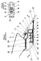
- An additional raised brake light is arranged in the passenger compartment of a vehicle behind a rear window (22) at the upper edge area of the rear window (22).
- a plate-shaped base element (1) made of plastic is fastened to the upper body panel (26) adjoining the rear window (22) at the fastening points (23) by means of screws (not shown).
- the plate-shaped base element (1) extends from the fastening points (23) to close to the rear window (22).
- a plurality of bowl-shaped reflectors (4) arranged next to one another are integrally formed on the downward-facing side of the base element (1).
- An opening for receiving a lamp (5) is made in the region of its apex in the reflectors (4) and can be inserted into the opening from the front of the reflector (4).
- the lamps (5) engage with their glass base in a neck surrounding the opening on the rear of the reflector (4) and are connected to electrical contact devices (24) with their glass base.
- the contact devices (24) consist of plug elements which are arranged in the neck of the reflector (4) and are connected to conductor tracks.
- a horizontal wall (25) running approximately over the entire length of the lamp is formed in the center of the rear of the reflectors (4) and carries the conductor tracks of the electrical contact devices (24) for the lamp (5) in its end directed against the light exit direction.
- the reflectors (4), the wall (25) and most of the base element (1) are covered by a cover (3).
- the cover hood (3) extends from the reflectors (4) to the inside of the rear window (22) so that no interference light can arise in the passenger compartment.
- a seal (27) is arranged between the cover (3) and the rear window (22).
- the cover (3) lies with its edge section directed against the light exit direction against a panel (28) which is permanently connected to the body panel (26).
- the reflectors (4) are closed on their front by a bowl-shaped translucent lens (2), the side wall of which has an edge section (17) on the inside the cover (3) is in contact.
- the lens (2) is fixed to the cover (3) by several tongue and groove connections (18).
- the spring of these connections consists of a pin formed on the inside of the cover (3) and the groove of a corresponding opening in the lateral edge section (17) of the lens (2).
- the lens (2) is held on the cover (3) and the cover (3) on the base element (1) by several spring elements (7).
- the spring elements (7) are made from a strip-shaped spring plate and run in their main extent approximately in the direction of light exit.
- the spring elements (7) are fastened to the cover (3) approximately centrally by means of a fastening device (13).
- the fastening devices (13) consist of a locking lug (14) molded onto the inside of the cover (3), which engages in a rectangular opening (15) of the spring element (7).
- the opening (15) is made in the bottom of a depression (16) of the spring element (7) drawn towards the base part (1).
- the locking lug (14) is spaced apart from the inside of the cover (3) and thus the spring element (7) can be firmly clamped between the locking lug (14) and the inside of the cover (3).
- the spring element (7) has a first section (8) which runs towards the lens (2) and, with its free end section, bears against the inside of the lateral edge section (17) of the lens (2) under pre-tension and presses the lateral edge section (17) against the inside of the cover (3).
- the spring element (7) has a third section (19) pointing away from the lens (2), which is angled with its free end section (20) towards the base element (1).
- the free end of the end section (20) bears against a support element (21) and presses both the third section (19) against the inside of the cover (3) and an edge of the cover Opening (15) against a lug (14) carrying approach.
- the support element (21) consists of a wall running transversely to the light exit direction and pointing towards the base element (1) and a latching projection of the wall pointing in the light exit direction.
- the free end section of the first section (8) bears against the lateral edge section (17) of the lens (2) and the locking lug (14), which counteracts the Direction of light exit, automatically engages behind an edge of the opening (15), and the free end of the end section (20) of the third section (19) automatically engages behind the latching projection of the support element (21) and is pretensioned on the latching projection and the wall of the support element (21).
- a tongue-shaped second section (9) is cut freely from the first section (8) and the third section (19) of the spring element (7).
- the tongue-shaped second sections (9) adjoin the fastening device (13) with their roots and extend approximately in the longitudinal direction in the light exit direction.
- the tongue-shaped second sections (9) are bent at their roots around a bending line running transversely to the longitudinal extension of the spring element (7) towards the base element (1).
- the free end sections of the tongue-shaped second sections (9) each have a bend (12). The bend adjacent to the first section points in the light exit direction, while the bend (12) adjacent to the third section (19) is directed counter to the light exit direction.
- the two second sections (9) are passed through a latching opening (11) in the wall (25) of the base element (1) and, with their deflection (12), engage in an undercut (10) formed by the edge of the latching opening (11).
- the bends (12) have such run-up surfaces on opposite sides that the engagement in the undercut (10) can be produced automatically and can be released automatically.
- the cover (3) After the cover (3) has been placed on the base element (1), the cover (3) lies in front of the reflectors (4) via the lens (2) on the base element (1) and behind the reflectors (4) either on the base element ( 1) or the cover (28).
Landscapes
- Engineering & Computer Science (AREA)
- Mechanical Engineering (AREA)
- Non-Portable Lighting Devices Or Systems Thereof (AREA)
- Lighting Device Outwards From Vehicle And Optical Signal (AREA)
- Securing Globes, Refractors, Reflectors Or The Like (AREA)
Applications Claiming Priority (2)
| Application Number | Priority Date | Filing Date | Title |
|---|---|---|---|
| DE4438491 | 1994-10-28 | ||
| DE4438491A DE4438491C1 (de) | 1994-10-28 | 1994-10-28 | Leuchte für Fahrzeuge |
Publications (3)
| Publication Number | Publication Date |
|---|---|
| EP0709251A2 true EP0709251A2 (fr) | 1996-05-01 |
| EP0709251A3 EP0709251A3 (fr) | 1996-11-20 |
| EP0709251B1 EP0709251B1 (fr) | 1999-05-19 |
Family
ID=6531895
Family Applications (1)
| Application Number | Title | Priority Date | Filing Date |
|---|---|---|---|
| EP95116215A Expired - Lifetime EP0709251B1 (fr) | 1994-10-28 | 1995-10-14 | Feux pour véhicule |
Country Status (3)
| Country | Link |
|---|---|
| EP (1) | EP0709251B1 (fr) |
| DE (2) | DE4438491C1 (fr) |
| ES (1) | ES2131246T3 (fr) |
Families Citing this family (5)
| Publication number | Priority date | Publication date | Assignee | Title |
|---|---|---|---|---|
| DE29602125U1 (de) * | 1996-02-08 | 1996-04-18 | Hella KG Hueck & Co., 59557 Lippstadt | Signalleuchte für Fahrzeuge |
| DE19616974A1 (de) * | 1996-04-27 | 1997-10-30 | Bayerische Motoren Werke Ag | Heckleuchte für Fahrzeuge |
| DE19640096C1 (de) * | 1996-09-28 | 1998-02-12 | Volkswagen Ag | Vorrichtung zum Befestigen eines Scheinwerfers oder einer Leuchte an einem Fahrzeugteil |
| DE19714367A1 (de) * | 1997-02-06 | 1998-08-13 | Itt Mfg Enterprises Inc | Signalleuchte für ein Fahrzeug |
| DE19853878A1 (de) * | 1998-11-23 | 2000-07-20 | Hella Kg Hueck & Co | Langgestreckte Signalleuchte für Fahrzeuge |
Citations (1)
| Publication number | Priority date | Publication date | Assignee | Title |
|---|---|---|---|---|
| EP0499081A1 (fr) | 1991-02-15 | 1992-08-19 | Yazaki Corporation | Feux stop pour véhicule |
Family Cites Families (7)
| Publication number | Priority date | Publication date | Assignee | Title |
|---|---|---|---|---|
| DE3538361C1 (de) * | 1985-10-29 | 1986-09-11 | Daimler-Benz Ag, 7000 Stuttgart | Zusatzbremsleuchte fuer Kraftfahrzeuge |
| JPH01175539A (ja) * | 1987-12-28 | 1989-07-12 | Koito Mfg Co Ltd | 自動車用ハイマウンテッドストップランプ |
| DE8913812U1 (de) * | 1989-11-23 | 1990-01-04 | Hella KG Hueck & Co, 4780 Lippstadt | Zusatzbremsleuchte |
| DE4035639A1 (de) * | 1990-11-09 | 1992-05-14 | Hella Kg Hueck & Co | Zusatzbremsleuchte fuer kraftfahrzeuge |
| DE9112853U1 (de) * | 1991-10-16 | 1992-01-02 | Hella KG Hueck & Co, 4780 Lippstadt | Zusatzbremsleuchte |
| DE9114246U1 (de) * | 1991-11-15 | 1992-01-09 | Hella KG Hueck & Co., 59557 Lippstadt | Leuchte für Kraftfahrzeuge |
| ES2088174T3 (es) * | 1992-03-03 | 1996-08-01 | Hella Kg Hueck & Co | Lampara para vehiculos. |
-
1994
- 1994-10-28 DE DE4438491A patent/DE4438491C1/de not_active Expired - Fee Related
-
1995
- 1995-10-14 DE DE59505963T patent/DE59505963D1/de not_active Expired - Fee Related
- 1995-10-14 ES ES95116215T patent/ES2131246T3/es not_active Expired - Lifetime
- 1995-10-14 EP EP95116215A patent/EP0709251B1/fr not_active Expired - Lifetime
Patent Citations (1)
| Publication number | Priority date | Publication date | Assignee | Title |
|---|---|---|---|---|
| EP0499081A1 (fr) | 1991-02-15 | 1992-08-19 | Yazaki Corporation | Feux stop pour véhicule |
Also Published As
| Publication number | Publication date |
|---|---|
| DE4438491C1 (de) | 1996-02-08 |
| EP0709251B1 (fr) | 1999-05-19 |
| ES2131246T3 (es) | 1999-07-16 |
| DE59505963D1 (de) | 1999-06-24 |
| EP0709251A3 (fr) | 1996-11-20 |
Similar Documents
| Publication | Publication Date | Title |
|---|---|---|
| DE19741522C2 (de) | Vormontierbare Baueinheit | |
| EP0439159A2 (fr) | Clapet anti-retour d'air | |
| DE19707094C1 (de) | Befestigungseinrichtung einer Leuchte für Fahrzeuge | |
| DE102005015973A1 (de) | Befestigungsvorrichtung für mindestens einen Sensor an einer Fahrzeugscheibe | |
| EP0789184B1 (fr) | Feu de signalisation allongé pour véhicules | |
| DE19534205C2 (de) | Elektrischer Steckverbinder | |
| EP1514771B1 (fr) | Dispositif de fixation d'un élément dans un orifice dans la pièce de carosserie | |
| EP0709251B1 (fr) | Feux pour véhicule | |
| DE19722005B4 (de) | Beleuchtungseinrichtung für Fahrzeuge | |
| DE3105691A1 (de) | Leuchteneinheit | |
| DE4406393A1 (de) | Scheinwerfer-Leuchteneinheit für Fahrzeuge | |
| EP0544725B1 (fr) | Feu arriere pour vehicules a moteur | |
| DE9405756U1 (de) | Scheinwerfer für Fahrzeuge | |
| DE3101398A1 (de) | Mehrkammerleuchte fuer fahrzeuge | |
| EP1795799A1 (fr) | Luminaire avec une platine support maintenue dans son espace intérieur | |
| DE29602125U1 (de) | Signalleuchte für Fahrzeuge | |
| EP0669224B1 (fr) | Lampe pour l'intérieur d'un véhicule | |
| EP0829677A1 (fr) | Armature lumineuse pour locaux humides | |
| EP3988875A1 (fr) | Appareil de réfrigération électroménager pourvu de module d'éclairage sur la face avant à émission lumineuse spécifique dirigée obliquement vers l'avant et en dessous | |
| EP0814685B1 (fr) | Meuble ferme, en particulier un meuble de cuisine avec dispositif d'eclairage integre dans le panneau arriere | |
| DE19757927C1 (de) | Signalleuchte für Fahrzeuge | |
| DE102006041145B4 (de) | Gassack-Einheit | |
| DE4433855C1 (de) | Innenleuchte für Fahrzeuge | |
| DE10061797B4 (de) | Leuchte | |
| DE3927818A1 (de) | Gehaeuse fuer steckkontakte und elektromotor mit einem solchen gehaeuse |
Legal Events
| Date | Code | Title | Description |
|---|---|---|---|
| PUAI | Public reference made under article 153(3) epc to a published international application that has entered the european phase |
Free format text: ORIGINAL CODE: 0009012 |
|
| AK | Designated contracting states |
Kind code of ref document: A2 Designated state(s): DE ES FR GB IT |
|
| PUAL | Search report despatched |
Free format text: ORIGINAL CODE: 0009013 |
|
| AK | Designated contracting states |
Kind code of ref document: A3 Designated state(s): DE ES FR GB IT |
|
| 17P | Request for examination filed |
Effective date: 19970324 |
|
| GRAG | Despatch of communication of intention to grant |
Free format text: ORIGINAL CODE: EPIDOS AGRA |
|
| GRAG | Despatch of communication of intention to grant |
Free format text: ORIGINAL CODE: EPIDOS AGRA |
|
| GRAH | Despatch of communication of intention to grant a patent |
Free format text: ORIGINAL CODE: EPIDOS IGRA |
|
| 17Q | First examination report despatched |
Effective date: 19981022 |
|
| GRAH | Despatch of communication of intention to grant a patent |
Free format text: ORIGINAL CODE: EPIDOS IGRA |
|
| ITF | It: translation for a ep patent filed | ||
| GRAA | (expected) grant |
Free format text: ORIGINAL CODE: 0009210 |
|
| AK | Designated contracting states |
Kind code of ref document: B1 Designated state(s): DE ES FR GB IT |
|
| PG25 | Lapsed in a contracting state [announced via postgrant information from national office to epo] |
Ref country code: GB Free format text: LAPSE BECAUSE OF FAILURE TO SUBMIT A TRANSLATION OF THE DESCRIPTION OR TO PAY THE FEE WITHIN THE PRESCRIBED TIME-LIMIT Effective date: 19990519 |
|
| REF | Corresponds to: |
Ref document number: 59505963 Country of ref document: DE Date of ref document: 19990624 |
|
| REG | Reference to a national code |
Ref country code: ES Ref legal event code: FG2A Ref document number: 2131246 Country of ref document: ES Kind code of ref document: T3 |
|
| ET | Fr: translation filed | ||
| PGFP | Annual fee paid to national office [announced via postgrant information from national office to epo] |
Ref country code: ES Payment date: 19991007 Year of fee payment: 5 |
|
| PGFP | Annual fee paid to national office [announced via postgrant information from national office to epo] |
Ref country code: FR Payment date: 19991018 Year of fee payment: 5 |
|
| GBV | Gb: ep patent (uk) treated as always having been void in accordance with gb section 77(7)/1977 [no translation filed] |
Effective date: 19990519 |
|
| PLBE | No opposition filed within time limit |
Free format text: ORIGINAL CODE: 0009261 |
|
| STAA | Information on the status of an ep patent application or granted ep patent |
Free format text: STATUS: NO OPPOSITION FILED WITHIN TIME LIMIT |
|
| 26N | No opposition filed | ||
| PG25 | Lapsed in a contracting state [announced via postgrant information from national office to epo] |
Ref country code: DE Free format text: LAPSE BECAUSE OF NON-PAYMENT OF DUE FEES Effective date: 20000801 |
|
| PG25 | Lapsed in a contracting state [announced via postgrant information from national office to epo] |
Ref country code: ES Free format text: LAPSE BECAUSE OF NON-PAYMENT OF DUE FEES Effective date: 20001015 |
|
| PG25 | Lapsed in a contracting state [announced via postgrant information from national office to epo] |
Ref country code: FR Free format text: LAPSE BECAUSE OF NON-PAYMENT OF DUE FEES Effective date: 20010629 |
|
| REG | Reference to a national code |
Ref country code: FR Ref legal event code: ST |
|
| REG | Reference to a national code |
Ref country code: ES Ref legal event code: FD2A Effective date: 20011113 |
|
| PG25 | Lapsed in a contracting state [announced via postgrant information from national office to epo] |
Ref country code: IT Free format text: LAPSE BECAUSE OF NON-PAYMENT OF DUE FEES Effective date: 20051014 |