EP3988875A1 - Appareil de réfrigération électroménager pourvu de module d'éclairage sur la face avant à émission lumineuse spécifique dirigée obliquement vers l'avant et en dessous - Google Patents
Appareil de réfrigération électroménager pourvu de module d'éclairage sur la face avant à émission lumineuse spécifique dirigée obliquement vers l'avant et en dessous Download PDFInfo
- Publication number
- EP3988875A1 EP3988875A1 EP21198578.3A EP21198578A EP3988875A1 EP 3988875 A1 EP3988875 A1 EP 3988875A1 EP 21198578 A EP21198578 A EP 21198578A EP 3988875 A1 EP3988875 A1 EP 3988875A1
- Authority
- EP
- European Patent Office
- Prior art keywords
- light
- snap
- housing part
- wall
- module
- Prior art date
- Legal status (The legal status is an assumption and is not a legal conclusion. Google has not performed a legal analysis and makes no representation as to the accuracy of the status listed.)
- Granted
Links
Images



Classifications
-
- F—MECHANICAL ENGINEERING; LIGHTING; HEATING; WEAPONS; BLASTING
- F25—REFRIGERATION OR COOLING; COMBINED HEATING AND REFRIGERATION SYSTEMS; HEAT PUMP SYSTEMS; MANUFACTURE OR STORAGE OF ICE; LIQUEFACTION SOLIDIFICATION OF GASES
- F25D—REFRIGERATORS; COLD ROOMS; ICE-BOXES; COOLING OR FREEZING APPARATUS NOT OTHERWISE PROVIDED FOR
- F25D25/00—Charging, supporting, and discharging the articles to be cooled
- F25D25/02—Charging, supporting, and discharging the articles to be cooled by shelves
- F25D25/024—Slidable shelves
- F25D25/025—Drawers
-
- F—MECHANICAL ENGINEERING; LIGHTING; HEATING; WEAPONS; BLASTING
- F25—REFRIGERATION OR COOLING; COMBINED HEATING AND REFRIGERATION SYSTEMS; HEAT PUMP SYSTEMS; MANUFACTURE OR STORAGE OF ICE; LIQUEFACTION SOLIDIFICATION OF GASES
- F25D—REFRIGERATORS; COLD ROOMS; ICE-BOXES; COOLING OR FREEZING APPARATUS NOT OTHERWISE PROVIDED FOR
- F25D27/00—Lighting arrangements
-
- F—MECHANICAL ENGINEERING; LIGHTING; HEATING; WEAPONS; BLASTING
- F25—REFRIGERATION OR COOLING; COMBINED HEATING AND REFRIGERATION SYSTEMS; HEAT PUMP SYSTEMS; MANUFACTURE OR STORAGE OF ICE; LIQUEFACTION SOLIDIFICATION OF GASES
- F25D—REFRIGERATORS; COLD ROOMS; ICE-BOXES; COOLING OR FREEZING APPARATUS NOT OTHERWISE PROVIDED FOR
- F25D11/00—Self-contained movable devices, e.g. domestic refrigerators
- F25D11/02—Self-contained movable devices, e.g. domestic refrigerators with cooling compartments at different temperatures
-
- F—MECHANICAL ENGINEERING; LIGHTING; HEATING; WEAPONS; BLASTING
- F25—REFRIGERATION OR COOLING; COMBINED HEATING AND REFRIGERATION SYSTEMS; HEAT PUMP SYSTEMS; MANUFACTURE OR STORAGE OF ICE; LIQUEFACTION SOLIDIFICATION OF GASES
- F25D—REFRIGERATORS; COLD ROOMS; ICE-BOXES; COOLING OR FREEZING APPARATUS NOT OTHERWISE PROVIDED FOR
- F25D23/00—General constructional features
-
- F—MECHANICAL ENGINEERING; LIGHTING; HEATING; WEAPONS; BLASTING
- F25—REFRIGERATION OR COOLING; COMBINED HEATING AND REFRIGERATION SYSTEMS; HEAT PUMP SYSTEMS; MANUFACTURE OR STORAGE OF ICE; LIQUEFACTION SOLIDIFICATION OF GASES
- F25D—REFRIGERATORS; COLD ROOMS; ICE-BOXES; COOLING OR FREEZING APPARATUS NOT OTHERWISE PROVIDED FOR
- F25D29/00—Arrangement or mounting of control or safety devices
-
- F—MECHANICAL ENGINEERING; LIGHTING; HEATING; WEAPONS; BLASTING
- F25—REFRIGERATION OR COOLING; COMBINED HEATING AND REFRIGERATION SYSTEMS; HEAT PUMP SYSTEMS; MANUFACTURE OR STORAGE OF ICE; LIQUEFACTION SOLIDIFICATION OF GASES
- F25D—REFRIGERATORS; COLD ROOMS; ICE-BOXES; COOLING OR FREEZING APPARATUS NOT OTHERWISE PROVIDED FOR
- F25D2400/00—General features of, or devices for refrigerators, cold rooms, ice-boxes, or for cooling or freezing apparatus not covered by any other subclass
- F25D2400/36—Visual displays
Definitions
- One aspect of the invention relates to a household refrigeration appliance with a housing.
- a housing In the housing there is a first receiving space for foodstuffs, which is at the top when viewed in the height direction.
- a second, lower receiving space for food which is separate from the first receiving space, is formed in the housing.
- the two receiving spaces Viewed in the depth direction of the household refrigeration appliance, the two receiving spaces are separated from one another at the front by a crossbar of the household refrigeration appliance.
- the household refrigeration appliance also has a light module, which is arranged on a front side of the crossbeam.
- the light module has a module housing.
- the module housing Viewed in the depth direction of the household refrigeration appliance, the module housing has a front housing part. This front housing part has a bottom wall which is a light exit window.
- a lighting unit In the case of domestic refrigeration appliances with a plurality of accommodation spaces, it is known for a lighting unit to be arranged on a front side of a cross connection.
- the cross connection separates a cold room from a freezer room. Light can be emitted downwards through this lighting unit, which is arranged at the front in a locally specified manner.
- This lamp unit has a one-piece housing. A transparent cover is arranged on this housing. This cover snaps directly to the cross-connection with a projection in the form of a rib. The housing snaps directly to a fastener. The fastener is separate from the housing and separate from the cover. The fastening element is arranged directly on the cross connection.
- fastening lugs of the metallic fastening element must be passed through fastening openings in the cross connection and then bent over the edges of the fastening openings and clamped to them.
- the cover which is convex in cross section in the front area, is covered on the inside by a non-transparent apron. This prevents light from escaping to the front.
- the lighting unit known from the prior art is made up of a variety of components that have to be individually connected in a very complex manner.
- the installation effort of the housing on the separate mounting bracket and in particular also the attachment of this mounting bracket to the cross connection are very assembly-intensive. This also results in position tolerances. It is therefore very difficult to permanently position the lighting unit in an accurately positioned position on the cross connection.
- the lighting functionality of this lighting unit is limited. Due to the arrangement of the light source in the housing and the shape of the cover, the light can only be emitted downwards with a vertical main emission direction. In a particularly disadvantageous manner, this results in only one lighting option in a very narrow area below the lighting unit.
- a bright spot of light forms as a result immediately below the lighting unit and on the front side of the cross connection which is adjacent in this regard. This prevents a homogeneous appearing light image.
- water and moisture can get into the housing through the mounting bracket.
- One aspect of the invention relates to a household refrigeration appliance with a housing.
- a housing In the housing there is a first receiving space for foodstuffs, which is at the top when viewed in the height direction.
- a second, lower receiving space for food which is separate from the first receiving space, is formed in the housing.
- the two receiving spaces Viewed in the depth direction of the household refrigeration appliance, the two receiving spaces are separated from one another at the front by a crossbar of the household refrigeration appliance.
- the household refrigeration appliance also has a light module, which is arranged on a front side of the crossbeam.
- the light module has a module housing.
- the module housing Viewed in the depth direction of the household refrigeration appliance, the module housing has a front housing part. This front housing part has a bottom wall which is a light exit window.
- a lower wall of the front housing part viewed in the height direction, has a partial area or a partial section.
- This sub-area is oriented obliquely upwards relative to a horizontal line. This means that viewed in the depth direction, starting from an end or a side of this sub-area that is closer to the crossbar, this sub-area of the lower wall is oriented upwards and forwards.
- a rectilinear and continuous oblique orientation is formed here.
- a light channel is formed inside the module housing. This light channel defines and in accordance with the intended purpose a light outlet and thus in particular a main emission direction of the light out of the module housing through the lower wall at an angle to a vertical.
- the light module therefore has a very specific, directed light emission downwards and diagonally forwards.
- a zone that lies in front of the lower, second receiving space in the depth direction of the household refrigeration appliance is illuminated, in particular homogeneously and relatively large.
- the angle between the vertical and the main emission direction is between 20° and 70°, in particular between 25° and 60°.
- the light channel has a reflection wall.
- This reflection wall is oriented obliquely to the vertical.
- the light from a light source of the light module is reflected in the module housing by this reflection wall in a direction away from the crossbeam.
- the light is reflected into the desired light exit orientation by this one reflection wall.
- the lower wall has a further partial area for light exit.
- This further sub-area ends at an end of the sloping sub-area that faces away from the crossbeam viewed in the depth direction.
- the partial area is more inclined upwards relative to the horizontal than the sloping, first partial area.
- this is provided such that, viewed in the height direction, this line of light is positioned in a gap between the upper door, which closes the upper accommodation space, and the lower door, which closes the lower accommodation space. Even when the doors are closed, the gap between the doors can then be illuminated by this line of light. In this way, for example, the lower edge and the upper edge of these two doors can be optically signaled even when there is a greater distance and/or when visibility is dark.
- the further partial area of this lower wall has a vertically oriented outer side.
- this further partial area can also have a vertically oriented inner side. In this regard, a very individual emission of light can then take place towards the front out of the module housing.
- the outside of the sloping first portion of the bottom wall is planar. In one embodiment, the inside of this sloping, first portion of the bottom wall can be oriented parallel to the outside.
- this further sub-area is also present, there is a kink or an angular transition between the outside of the oblique, first sub-area and the directly adjoining outside of the further, second sub-area.
- the front housing is formed from plastic with the top wall and the bottom wall.
- this housing part is a one-piece component. In particular, it can be a 2K component.
- the module housing has a rear housing part, viewed in the depth direction of the household refrigeration appliance.
- This rear housing part has a back wall and several separate snap elements.
- the snap elements are formed in one piece with the rear housing part.
- the snap elements are snapped into snap element receptacles formed on the cross member.
- the rear housing part is arranged with a rear surface of the rear wall, viewed in the depth direction, lying flat on the front side of the crossbeam.
- a configuration of this type enables the light module to be attached directly to the crossbeam in a particularly simple and nevertheless positionally stable manner. The assembly effort is reduced in this regard.
- a very quick and effective assembly concept can be provided by means of snap connections.
- this multiple snap-on elements and multiple snap-on element receptacles also enable the light module to be attached in a permanently fixed position.
- the module housing itself is in direct contact with the front side of the crossbeam.
- the integrally formed snaps extend rearwardly through snap-fit receptacles and are snapped therein. A simple fastening concept is thus made possible.
- fastening brackets that are separate from the housing are no longer required, as is necessary in the prior art.
- a first, off-center snap element and a separate second, off-center snap element are formed on the rear wall.
- these snap elements viewed in the width direction of the domestic refrigeration appliance and thus also viewed in the width direction of this rear wall, are arranged offset to the left and to the right in relation to a midpoint or a center of the rear wall.
- these two snap elements are arranged symmetrically to a center of the rear housing part, viewed in the width direction of this rear wall and thus of the rear housing part in one exemplary embodiment.
- the snap-in element receptacle in the crossbeam is designed symmetrically to a center point of this crossbeam viewed in the width direction. This then also makes it possible for this crossbeam to be mounted symmetrically in a fold-over position. It is therefore no longer necessary during production to pay close attention to the only single installation position in which the crossbar has to be arranged. Rather, a first position and a second position of the cross member rotated by 180° (again, here about an axis viewed in the depth direction) are also possible. In particular, this also has the advantage that after the installation of a backing part behind the crossbeam, in particular together with an electrical plug, on this center crossbeam or crossbeam, the symmetry of this crossbeam is retained. In particular, therefore, a production worker does not have to pay attention to which side of the crossbar the inner container, which delimits the first receiving space, and on which side the inner container, which delimits the second receiving space, must be arranged.
- a central snap element is formed on the rear wall and is arranged centrally in the width direction of the rear housing part.
- a mechanically stable attachment of the rear housing part directly to the crossbeam is further improved in a particularly advantageous manner.
- this arrangement also continues to provide the above-mentioned advantages of the symmetry of the envelope.
- a central central snap-in element receptacle is formed in the crossbeam. The central snap element can snap into this.
- the crossbeam continues to be designed, in particular, to be symmetrically folded over, so that the above-mentioned advantages are retained.
- the central snap includes two spaced apart snap portions. These snap element parts are each snapped into one, in particular a single central, snap element receptacle of the crossbar. This configuration of the central snap element is a allows particularly advantageous mechanical coupling. In addition, these snap element parts can be used in an improved way for additional functions.
- these snap-on element parts have snap-in lugs on the sides facing away from one another.
- the snap element parts are snapped into the snap element receptacle in the crossbeam with these snap lugs.
- the intermediate space between the snap-in element parts remains maximized when viewed in this width direction. This space can thus be better used for the introduction of other components.
- a particularly compact construction, in particular in the depth direction of the light module, is also made possible as a result.
- the snap element parts are formed with engaging elements on the mutually facing sides. These engagement elements are designed to engage in engagement areas of the circuit board of the light module.
- the snap element parts thus have multifunctionality. On the one hand, they are intended to be snapped onto the crossbeam itself, and on the other hand, they are intended to be intended to hold the circuit board in a direct snapping manner.
- the board is held securely in position in at least two spatial directions, in particular the depth direction and the width direction. In particular, it extends into the space between the snap element parts.
- the circuit board is arranged in an overlapping manner with this central snap element.
- the width direction it is also protected laterally by these snap element parts.
- the snap-on element parts extend, viewed in the depth direction, at least over the entire depth of the partial area of the circuit board that extends into the intermediate space between the snap-on element parts.
- the snap element parts have receiving and guide slots for a partial area of the circuit board on the inner sides facing one another.
- a receiving area for a partial area of the circuit board of the light module is formed between the snap element parts. This receiving area is thus intended to be provided so that this sub-area of the circuit board can be positioned therein.
- a portion of the circuit board is held between the snap member portions.
- this partial area is snapped onto it by the engagement of the engagement elements in these engagement areas.
- the engaging elements extend in the width direction, as do the engaging portions. Thus, an interlocking is formed in the width direction.
- the snap-in elements are arranged resiliently on the rear wall, in particular in the width direction. As a result, the snapping process can be implemented in a particularly smooth manner.
- the crossbeam has a horizontal slot, which is designed to allow the circuit board to extend through. A portion of the circuit board extends through this slot in the cross member.
- the slot is formed centrally in the cross member. This makes it possible for the circuit board to extend on both sides of the crossbeam in the assembled state. As a result, a compact construction of the light module can also be achieved and a more secure positioning of the circuit board is achieved.
- the partial area of the circuit board that extends through this slot which in particular also forms the entrance of the central snap-in element receptacle, of the crossbar to the rear into the housing of the household refrigeration appliance, is designed with electrical contacts that are intended for electrically contacting a plug, which is arranged in the housing are formed.
- electrical contacts are formed in this regard.
- electrical contacting with a three-pole plug can thus be made possible.
- Such a three-pin connector with related contacts on the part of the circuit board which relates to a central first electrical contact of the first polarity and to the left and right of it a further electrical contact of a second polarity, also enables the above-mentioned symmetrically folded assembly.
- the two outer electrical contacts of these three electrical contacts are connected to one another in this context. This to the effect that the light module is functional regardless of the installation position of the plug.
- the positive pole of the electrical plug is arranged in the middle. It is therefore provided that the electrical contact on the partial area of the circuit board that is arranged in the middle is a positive pole and thus has this first polarity.
- that part of the circuit board that extends backwards through the slot in the crossbar into the housing of the household refrigeration appliance is narrower than another part of the circuit board that is arranged in front of the crossbar.
- the circuit board has a T-shape.
- a portion of the board is a T-stem.
- this portion is that which extends rearwardly through a slot in the rear wall of the rear housing portion.
- this T-stem also extends through the recess or the snap-in element receptacle in the crossbeam.
- Another part of this T-shape is a T-roof.
- This further partial area is arranged on the front side of the rear wall of the rear housing part. It thus does not extend through the slot in the rear wall of the rear housing part.
- the slot in the back panel is narrower than the T-top of the board. Due to this shape and the arrangement of the circuit board relative to this rear wall, it can also be positioned more stably. In particular, a particularly compact structure is also made possible.
- the module housing has a front housing part, viewed in the depth direction of the household refrigeration appliance. This thus extends further forward than the rear housing part.
- these two housing parts are permanently connected. This means in particular that they are initially manufactured and provided as separate components.
- the front housing part and the rear housing part are each formed in one piece. They are then inextricably linked. For example, they can be ultrasonically welded in this context. A non-destructive, detachable separation of these two housing parts is then not possible.
- the front housing part has a lower wall, viewed in the vertical direction of the domestic refrigeration appliance.
- This lower wall forms a light exit window of the light module.
- the lower wall is oriented obliquely upwards relative to a horizontal line. This means that it is oriented obliquely upwards and forwards, starting from that end or that side which faces the crossbar and is closer to the crossbar in this respect.
- the light with a main emission direction cannot be emitted vertically downwards, but can be emitted obliquely downwards and forwards away from the recording space.
- a particularly homogeneous illumination of this zone can thus be made possible.
- Undesirable light spots, which occur directly below the light module, especially on the front side of the crossbeam, can be avoided in this way.
- the household refrigeration appliance has a food storage container which is arranged in a displaceable manner in the second storage space. It is thus then possible for this food receptacle to be uniformly illuminated from above by the light module when it is pulled out in a position that is then also pulled out in this respect. A particularly comprehensive and homogeneous illumination of the interior of this food storage container is thus also made possible in the maximum extension position of this container.
- the food receiving container is in particular a tray. This can also be pulled out of the second receiving space and pushed in linearly in the depth direction will. It is precisely this very advantageous design of the light module with this sloping wall and the corresponding light output that enables the entire interior of this shell to be illuminated as extensively and uniformly as possible, even if this shell is relatively large and is pulled relatively far forward .
- the front housing part has an upper wall viewed in the vertical direction.
- This top wall is opaque. This ensures that no undesired light emerges upwards. A highly directional light extraction via this specified lower wall is thereby made possible. In particular, this also avoids dazzling an observer who is looking at the light module from above or at an angle. In particular, when a shell as explained above is present and this is pulled out and the observer looks into the interior of the shell from above, it is illuminated uniformly and circumferentially and the observer is not dazzled by the light module.
- this upper wall is oriented obliquely downwards with respect to a horizontal line. This means that viewed in the depth direction, starting from that end or that side which is closer to the crossbeam, it is oriented obliquely downwards and forwards.
- This geometry achieves a particularly advantageous forward tapering of the front housing part on both sides. This reduces the space required by the light module at the top and bottom.
- an advantageous geometry is achieved in this context. Due to this orientation of the front housing part, which is inclined both upwards and downwards, the geometry of this front housing part is tapered in cross section. As a result, only a minimal amount of space is required in the vertical direction between the doors of this front housing part.
- this upper wall is also designed as an information presentation wall due to its defined and intended oblique orientation.
- This information presentation wall is therefore intended to contain information in particular a piece of text information is displayed.
- this text information can also be formed permanently on the top wall.
- This text information can be information about the light module itself. However, other information is also possible that can be displayed on this information presentation wall.
- an electronic display can also be formed on this top wall. This allows electronic information to be displayed visually.
- the front housing portion is truncated pyramid shaped.
- the household refrigeration appliance 1 is designed for storing and preserving food.
- the domestic refrigeration appliance 1 can be a refrigerator or a freezer or in particular a fridge-freezer combination appliance.
- the household refrigeration appliance 1 is a fridge-freezer combination appliance.
- the domestic refrigeration appliance 1 has a housing 2 .
- a first receiving space 3 is arranged in the housing 2 .
- a second receiving space 4 separate from the first receiving space 3 is arranged.
- the two receiving spaces 3 and 4 are intended to be designed for storing and preserving food.
- the two receiving spaces 3 and 4 are vertical (y-direction) arranged in series with each other.
- the receiving spaces 3 and 4 are each delimited by walls of inner containers. Viewed from the front (in the depth direction—z-direction), the receiving spaces 3 and 4 have charging openings. In this regard, they are delimited at the front by front edges or front flanges 5 . Such a front flange is formed by a cross member 6 in the vertical direction (y-direction) between the two receiving spaces 3 and 4 .
- the crossbeam 6 is thus oriented in the width direction. In this regard, it is designed as a horizontal rectangular plate.
- the upper receiving space 3 is separated from the lower receiving space 4 by this crossbar 6 .
- the crossbeam 6 can be made of metal.
- the household refrigeration appliance 1 also has a first door 7 .
- the first door 7 is arranged on the housing 2 in a pivotable manner. It is arranged to close the upper, first receiving space 3 .
- the household refrigeration appliance 1 has a second door 8 that is separate from the first door 7 .
- the second door 8 is pivotably arranged on the housing 2 . It is intended to be arranged to close the lower receiving space 4 .
- the two doors 7 and 8 can be moved independently. In the closed state, the two doors 7 and 8 are front-side external parts of the household refrigeration appliance 1. They then extend, in particular, in a common plane.
- a gap 9 is formed between the two doors 7 and 8 .
- the domestic refrigeration appliance 1 has a light module 10 .
- the light module 10 is arranged on the crossbeam 6 at the front.
- the light module 10 is positioned in such a way that it is arranged in the area of the gap 9 .
- In 2 is shown in a perspective view of the crossbeam 6 with the light module 10 arranged thereon.
- the crossbeam 6 is in particular made of sheet metal. In particular, it is designed in one piece.
- the light module 10 is arranged directly on a front side 11 of this crossbeam 6 and is forward when viewed in the depth direction.
- the crossbeam 6 is shown with a view of the front side 11 . It can be seen that snap element receptacles 12 and 13 are formed on the crossbar 6 . In the width direction (x-direction), these two eccentric snap-in element receptacles 12 and 13 are formed symmetrically to a center M of the crossbar 6 .
- a central snap element receptacle 14 is formed in the exemplary embodiment. In particular, it is designed centrally and symmetrically to the center M. In this exemplary embodiment of the crossbeam 6, it can thus be installed on the housing 2 in a symmetrical fashion.
- the crossbeam 6 only has holes that form entrances for the snap element receptacles 12 , 13 , 14 .
- These partial elements, on which the snap elements then snap, can then be attached to a further component 6a ( figure 5 ) be trained.
- This component 6a can be separate from the crossbeam 6 and can be arranged directly on it. It can also be designed in one piece with the crossbeam 6 .
- the light module 10 has a module housing 15 .
- This module housing 15 has a further housing part 16 viewed in the depth direction.
- this rear housing part 16 is designed in one piece. In particular, it is made of plastic. In this regard, it can be an injection molded component.
- the housing 15 also has a front housing part 17 viewed in the depth direction. This is in particular formed in one piece.
- the front housing part 15 and the rear housing part 16 are initially manufactured and provided as individual, one-piece components. In the fully assembled state of the light module 10, these two housing parts 16 and 17 are permanently connected in one embodiment. In particular, they are ultrasonically welded in this regard. In this way, tightness, in particular against moisture, is achieved in the interior of this module housing 15 in a particularly advantageous manner.
- the rear housing part 16 has a plate-like rear wall 18 . Provision is made on a rear face 19a of this rear wall 18 for two off-centre snap elements 20 and 21 to be formed. You are in this regard integral with the Rear wall 18 formed.
- the two eccentric snap elements 20 and 21 are in particular arranged symmetrically to a center M1 of the rear housing part 16 . They are intended to be designed to snap into the off-centre snap-in element receptacles 12 and 13 on the crossbar 6 .
- the rear housing portion 16 includes a central snap member 22 . This is separated from the off-center snap elements 20 and 21 and formed in addition thereto.
- the central snap element 22 is formed symmetrically about the center M1.
- This central snap element 22 is designed to be snapped into the central snap element receptacle 14 on the crossbeam 6 .
- the two snap element parts 23 and 24 are spaced apart from one another in a defined manner in the width direction (x-direction), so that a receiving area 25 is formed between these snap element parts 23 and 24 .
- the snap element parts 23 and 24 formed in one piece on the rear surface 19a are each formed with snap lugs 26 and 27. These snap lugs 26 and 27 are formed on opposite sides 28 and 29 of the snap element parts 23 and 24 .
- the snap element part 23 has an engagement element 30 .
- the further snap element part 24 also has such an engagement element 31 . It is oriented towards the other snap element part 23 .
- These engagement elements 30 and 31 are intended to engage in engagement areas 32 and 33 of a circuit board 34 of the light module 10 .
- the circuit board 34 has a partial area 35 which, in the installed state, extends through a slot 36 in the rear wall 18 . This portion 35 is plate-like. In the mounted state, it then also extends into this receiving area 25 . In the width direction, it is bordered on the left and right by the snap element parts 23 and 24 or also held in this respect.
- the snap element parts 23 have guide slots 37 and 38 .
- This partial area 35 viewed in the width direction, engages in these and is guided accordingly.
- the engagement elements 30 and 31 In the mounted State are the engagement elements 30 and 31 in this engagement areas 32 and 33 engaging.
- snapping is provided here.
- the circuit board 34 is T-shaped.
- this first partial area 35 which has already been explained, forms a T-trunk.
- Another portion 39 of this board 34 forms a T-roof.
- This T-roof represents a narrow strip or web that extends with its longitudinal axis in the width direction.
- this further partial area 39 is arranged in front of the rear wall 18 when viewed in the depth direction. It therefore does not extend through the slot 36.
- the further partial area 29 bears in particular on a front surface 19b of the rear wall 18.
- light sources 40 are arranged on this further partial area 39, which 4 cannot be seen, but are indicated by the reference number. In particular, these light sources are arranged on an underside 41 of this further partial area 39 .
- the light sources 40 are, in particular, light-emitting diodes.
- electrical contacts are arranged on a top side 42 of this first partial area 35 .
- these are three electrical contacts 43, 44 and 45.
- These electrical contacts are arranged symmetrically with respect to the center M1 if the circuit board 34 has been correspondingly mounted on the rear housing part 16.
- the electrical contact 45 is in the middle. It is a first polarity contact. In particular, he is a positive pole in this regard.
- the two other contacts 43 and 44 are of the second polarity. In particular, they are negative poles.
- an electrical plug (not shown), in particular a three-pin plug, which is arranged in the housing 2 , can be electrically contacted with this circuit board 34 in a simple and reliable manner.
- circuit board 34 is also held securely and precisely in the module housing 15, in particular on the rear housing part 16, in the assembled state.
- the front housing part 17 is in the form of a truncated pyramid. It has a top wall 46 in one embodiment. This is formed opaque. The top wall 46 is opposite a horizontal line H ( 6 ) oriented diagonally downwards and forwards, starting from the side close to the crossbeam.
- the upper wall 46 is designed with an outer side 47 as an information presentation wall. As intended, text information 47a can be displayed on this. This can be permanently attached text information. However, electronic information can also be displayed on a display that may be integrated in this regard.
- the front housing part 17 has a lower wall 48 when viewed in the height direction.
- the bottom wall 48 is at least partially transparent to light in the visible spectral range. It represents a light emission window 49 ( 6 ) ready.
- this lower wall 48 is oriented with a portion 50 to the horizontal H obliquely upwards. This means that, starting from a side or an end of this lower wall 48, which is closer to the crossbar 6, an upward and forward orientation is provided.
- an outer side 51 of this partial area 50 oriented obliquely upwards is rectilinear in the sectional view. This means that this surface of the partial area 50 is flat in one embodiment.
- An inner side 52 of this partial area 50 can also be flat.
- a specific light channel 53 is formed inside the module housing 15 .
- the light L of the light source 40 is caused to exit the module housing 15 via the lower wall 48 in a targeted manner.
- this light channel 53 achieves a defined and directed exit of light from the module housing 15 via this lower wall 48 .
- this light channel 53 has a reflection wall 54 in one exemplary embodiment. This is oriented obliquely to a vertical V. This is such that the reflected light emerges from this module housing 15 at an angle to the front and downwards relative to this vertical V.
- a zone 55 which is located in front of the lower receiving space 4 in the depth direction, is thus illuminated homogeneously and also further forward.
- the lower wall 48 has a further partial area 56 .
- This sub-area 56 adjoins the oblique first sub-area 48 at the top in the vertical direction.
- the further partial area 56 is permeable to light in the visible spectral range.
- This exemplary embodiment also makes it possible for light L to be emitted to the outside not only via the partial area 50 but also via this further partial area 56 .
- This further sub-area 56 is more inclined relative to the horizontal H than the obliquely oriented sub-area 48.
- the further sub-area 56 is oriented vertically.
- an outer side 57 is oriented vertically.
- An inner side 58 can also be correspondingly oriented vertically.
- the outside 57 is preferably flat.
- the inside 58 is also flat.
- a kink 59 is formed between the outside 57 and the outside 51 .
- the advantageous geometry of the module housing 15 can also be seen.
- a maximum distance from the doors 7 and 8 is achieved by these inclined upper and lower walls 46 and 48 .
- the freedom of movement of the doors 7 and 8 is not restricted, in particular in the depth direction towards the crossbar 6.
- a lowering of the upper door 7 occurring in the height direction can, for example, occur after loading with stored goods in door racks, which occurs over the service life of the household refrigeration appliance 1.
- Such a movement of the door is then not harmful to the light module 10, so that no undesired contact occurs in this regard.
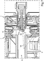
- FIG 5 is a horizontal sectional view through the arrangement according to FIG 2 shown along section line VV.
- the mounted end state of the light module 10 on the crossbeam 6 can be seen.
- the rear wall 18 rests flat with the rear surface 19a on the front side 11 of the crossbeam 6 .
- the off-center snaps 20 and 21 snap into the off-center snap receptacles 12 and 13 .
- the snap element parts 23 and 24 are also snapped into the snap element receptacle 24 .
- the engaged state between the engaging elements 30 and 31 of the engaging portions 32 and 33 is shown.
- the partial area 35 has further slots 60 and 61 .
- Webs 63 and 64 engage in these rearwardly open slots 60 and 61, which are formed on a rear edge 62 of the portion 35.
- These webs 63 and 64 are part of a coupling component with which the light module 10 is coupled in this respect in the assembled final state.
- These webs 63 and 64 can be integrated into the component 6a.
- the component 6a can also accommodate the electrical plug.
- the snap elements 20 and 21 are hollow. As a result, they are lighter and have a certain deformability. For the sake of clarity, figure 5 no hatching of the section planes of the individual components is shown.
- the module housing 15 is designed to taper towards the front.
- a vertical sectional view of the domestic refrigeration appliance 1 in the area of the crossbeam 6 is shown.
- the doors 7 and 8 are shown here in the closed state.
- a first illumination area 65 is shown here as an example, which is generated when light L is emitted only over the partial area 50 of the lower wall 48 .
- a light area 66 is shown, which is emitted when, in addition to the light exiting via the oblique partial area 50, light L is emitted outward via the further partial area 56.
- FIG. 8 a vertical sectional view of the household refrigeration appliance 1 is partially shown in a schematic representation.
- the household refrigeration appliance 1 has a food receptacle 67 here. This is slidably arranged in the lower receiving space 4 in the depth direction.
- This food accommodating container 67 can be a tray, for example.
- This maximum extension position shown here in particular is also such that this shell is in the area of zone 55.
- the light L is radiated uniformly into the interior of this food accommodating container 67, so that this interior is illuminated homogeneously and extensively.
- this module housing 15 Due to the above-mentioned advantageous welding between the two housing parts 16 and 17, a minimum size of this module housing 15 is also achieved. This module housing 15 is minimized since there is no longer any need for installation space for separate snap elements, screw bosses and fastening elements or the like.
- the module housing 15 can be designed as a 2K component.
- a possible emission angle of the light L in this direction which is oriented obliquely forwards and downwards, can advantageously be generated.
- This further partial area 56 of the lower wall 48 can also be referred to as a diffuser.
Landscapes
- Engineering & Computer Science (AREA)
- Chemical & Material Sciences (AREA)
- Combustion & Propulsion (AREA)
- Physics & Mathematics (AREA)
- Mechanical Engineering (AREA)
- Thermal Sciences (AREA)
- General Engineering & Computer Science (AREA)
- Devices That Are Associated With Refrigeration Equipment (AREA)
Applications Claiming Priority (1)
| Application Number | Priority Date | Filing Date | Title |
|---|---|---|---|
| DE102020213397.2A DE102020213397A1 (de) | 2020-10-23 | 2020-10-23 | Haushaltskältegerät mit Lichtmodul an Frontseite mit spezifischer Lichtabstrahlung schräg nach vorne und unten |
Publications (2)
| Publication Number | Publication Date |
|---|---|
| EP3988875A1 true EP3988875A1 (fr) | 2022-04-27 |
| EP3988875B1 EP3988875B1 (fr) | 2024-06-26 |
Family
ID=77910724
Family Applications (1)
| Application Number | Title | Priority Date | Filing Date |
|---|---|---|---|
| EP21198578.3A Active EP3988875B1 (fr) | 2020-10-23 | 2021-09-23 | Appareil de réfrigération électroménager pourvu de module d'éclairage sur la face avant à émission lumineuse spécifique dirigée obliquement vers l'avant et en dessous |
Country Status (4)
| Country | Link |
|---|---|
| EP (1) | EP3988875B1 (fr) |
| CN (1) | CN114485027B (fr) |
| DE (1) | DE102020213397A1 (fr) |
| PL (1) | PL3988875T3 (fr) |
Cited By (1)
| Publication number | Priority date | Publication date | Assignee | Title |
|---|---|---|---|---|
| WO2025036250A1 (fr) * | 2023-08-11 | 2025-02-20 | 青岛海尔电冰箱有限公司 | Dispositif de conservation de fraîcheur pour réfrigérateur et réfrigérateur |
Citations (4)
| Publication number | Priority date | Publication date | Assignee | Title |
|---|---|---|---|---|
| JPH11132650A (ja) * | 1997-10-29 | 1999-05-21 | Toshiba Corp | 冷蔵庫 |
| EP1956325A2 (fr) | 2007-02-08 | 2008-08-13 | Liebherr-Hausgeräte Ochsenhausen GmbH | Appareil de réfrigération et/ou de refroidissement |
| EP2317264A1 (fr) * | 2009-10-27 | 2011-05-04 | BSH Bosch und Siemens Hausgeräte GmbH | Appareil de refroidissement doté d'un éclairage de l'espace intérieur |
| JP2019019987A (ja) * | 2017-07-11 | 2019-02-07 | 三菱電機エンジニアリング株式会社 | 保存庫及び電子冷蔵庫 |
Family Cites Families (10)
| Publication number | Priority date | Publication date | Assignee | Title |
|---|---|---|---|---|
| DE202006013233U1 (de) | 2006-08-29 | 2006-10-26 | BSH Bosch und Siemens Hausgeräte GmbH | Mehrtüriges Kältegerät mit beheizbarem Türholm |
| DE102015200193A1 (de) * | 2015-01-09 | 2016-07-14 | BSH Hausgeräte GmbH | Haushaltskältegeräte mit spezifischer Beleuchtungseinrichtung zur Ausleuchtung eines Nutzvolumens einer Schublade |
| US10400987B2 (en) * | 2015-01-30 | 2019-09-03 | Jarvis Corp. | Light fixture assembly including a reflector |
| CN204902360U (zh) * | 2015-06-08 | 2015-12-23 | 合肥华凌股份有限公司 | 立式冷柜 |
| DE102015007839B4 (de) | 2015-06-18 | 2017-05-04 | Emz-Hanauer Gmbh & Co. Kgaa | Beleuchtungsvorrichtung für ein elektrisches Haushaltsgerät |
| DE102017004608A1 (de) * | 2016-12-06 | 2018-06-07 | Liebherr-Hausgeräte Ochsenhausen GmbH | Kühl- und/oder Gefriergerät |
| EP3376145A1 (fr) | 2017-03-15 | 2018-09-19 | Liebherr-Hausgeräte Ochsenhausen GmbH | Appareil de réfrigération et/ou de congélation |
| DE102017006424B4 (de) * | 2017-07-07 | 2022-04-21 | Emz-Hanauer Gmbh & Co. Kgaa | Leuchtvorrichtung zum Einbau in eine Wandfläche eines elektrischen Geräts der Haushaltsausstattung |
| CN109915761B (zh) * | 2017-12-12 | 2022-04-05 | 夏普株式会社 | 间接照明装置和电器设备 |
| CN211120189U (zh) * | 2019-09-23 | 2020-07-28 | 沈阳海尔电冰箱有限公司 | 冰箱 |
-
2020
- 2020-10-23 DE DE102020213397.2A patent/DE102020213397A1/de active Pending
-
2021
- 2021-09-23 EP EP21198578.3A patent/EP3988875B1/fr active Active
- 2021-09-23 PL PL21198578.3T patent/PL3988875T3/pl unknown
- 2021-10-21 CN CN202111226131.8A patent/CN114485027B/zh active Active
Patent Citations (4)
| Publication number | Priority date | Publication date | Assignee | Title |
|---|---|---|---|---|
| JPH11132650A (ja) * | 1997-10-29 | 1999-05-21 | Toshiba Corp | 冷蔵庫 |
| EP1956325A2 (fr) | 2007-02-08 | 2008-08-13 | Liebherr-Hausgeräte Ochsenhausen GmbH | Appareil de réfrigération et/ou de refroidissement |
| EP2317264A1 (fr) * | 2009-10-27 | 2011-05-04 | BSH Bosch und Siemens Hausgeräte GmbH | Appareil de refroidissement doté d'un éclairage de l'espace intérieur |
| JP2019019987A (ja) * | 2017-07-11 | 2019-02-07 | 三菱電機エンジニアリング株式会社 | 保存庫及び電子冷蔵庫 |
Cited By (1)
| Publication number | Priority date | Publication date | Assignee | Title |
|---|---|---|---|---|
| WO2025036250A1 (fr) * | 2023-08-11 | 2025-02-20 | 青岛海尔电冰箱有限公司 | Dispositif de conservation de fraîcheur pour réfrigérateur et réfrigérateur |
Also Published As
| Publication number | Publication date |
|---|---|
| CN114485027A (zh) | 2022-05-13 |
| DE102020213397A1 (de) | 2022-04-28 |
| EP3988875B1 (fr) | 2024-06-26 |
| PL3988875T3 (pl) | 2024-10-07 |
| CN114485027B (zh) | 2024-04-30 |
Similar Documents
| Publication | Publication Date | Title |
|---|---|---|
| DE102008046983A1 (de) | Fahrzeuginnenraum-Beleuchtungslampeneinheit | |
| DE102007010023A1 (de) | Fahrzeugleuchte | |
| EP1159158B1 (fr) | Boitier metallique, notamment pour un appareil de commande d'airbag | |
| DE102014221784A1 (de) | Haushaltsgerät mit einer Eingabevorrichtung und einer Kodiervorrichtung | |
| EP4119876B1 (fr) | Appareil frigorifique électroménager doté d'un récipient interne et d'un module de source lumineuse disposé sur celui-ci, comportant un bord spécifique de sortie de la lumière | |
| EP3988875A1 (fr) | Appareil de réfrigération électroménager pourvu de module d'éclairage sur la face avant à émission lumineuse spécifique dirigée obliquement vers l'avant et en dessous | |
| DE102010001453A1 (de) | Kältegeräte, insbesondere Haushaltskältegerät | |
| DE202006003392U1 (de) | Fahrzeugleuchte | |
| DE19524381C2 (de) | Installationskanal mit einem zu einer Seite offenen metallischen Kanalprofil | |
| DE102020210278A1 (de) | Haushaltsgerät mit einer Kamera und einem damit verbundenen Hinterlegteil, sowie Verfahren | |
| DE102008054778A1 (de) | Bedieneinheit für ein Haushaltsgerät und Haushaltsgerät | |
| EP4001811A1 (fr) | Appareil électroménager de réfrigération doté d'une barre transversale et d'un module d'éclairage spécifique fixé à celle-ci | |
| DE10145528A1 (de) | Hochgesetzte Bremsleuchte für Fahrzeuge, insbesondere Kraftfahrzeuge | |
| EP2644984B1 (fr) | Verrouillage pour un couvercle de lampe | |
| DE102024100111A1 (de) | Zähler- und Verteilerschrank | |
| EP0709251B1 (fr) | Feux pour véhicule | |
| DE102019208449A1 (de) | Lebensmittel-Aufnahmebehälter mit einer auf unterschiedlichen Höhenlagen in verschiedenen Raumrichtungen gehaltenen Trennwand, sowie Verfahren zur Montage einer Trennwand | |
| EP3537077B1 (fr) | Compartiment de stockage pour produits à réfrigérer pourvu d'un cadre en l, porte ainsi qu'appareil de refroidissement électroménager | |
| EP0133299B1 (fr) | Boîtier d'armature lumineuse à parois d'extrémité rapportées | |
| DE4405721C1 (de) | Leuchte für den Innenraum von Kraftfahrzeugen | |
| EP1441181B1 (fr) | Boîtier pour une hotte d'extraction | |
| DE3537185C2 (fr) | ||
| EP0545124A1 (fr) | Dispositif de montage pour un appareil auxiliaire dans une ouverture prédécoupée d'un véhicule automobile | |
| DE102020212208A1 (de) | Haushaltskältegerät mit spezifisch ausgebildetem plattenartigem Beleuchtungsmodul | |
| DE10048382B4 (de) | Fahrzeugscheinwerfer und Reflektoreinheit hierfür |
Legal Events
| Date | Code | Title | Description |
|---|---|---|---|
| PUAI | Public reference made under article 153(3) epc to a published international application that has entered the european phase |
Free format text: ORIGINAL CODE: 0009012 |
|
| STAA | Information on the status of an ep patent application or granted ep patent |
Free format text: STATUS: THE APPLICATION HAS BEEN PUBLISHED |
|
| AK | Designated contracting states |
Kind code of ref document: A1 Designated state(s): AL AT BE BG CH CY CZ DE DK EE ES FI FR GB GR HR HU IE IS IT LI LT LU LV MC MK MT NL NO PL PT RO RS SE SI SK SM TR |
|
| STAA | Information on the status of an ep patent application or granted ep patent |
Free format text: STATUS: REQUEST FOR EXAMINATION WAS MADE |
|
| 17P | Request for examination filed |
Effective date: 20221027 |
|
| RBV | Designated contracting states (corrected) |
Designated state(s): AL AT BE BG CH CY CZ DE DK EE ES FI FR GB GR HR HU IE IS IT LI LT LU LV MC MK MT NL NO PL PT RO RS SE SI SK SM TR |
|
| GRAP | Despatch of communication of intention to grant a patent |
Free format text: ORIGINAL CODE: EPIDOSNIGR1 |
|
| STAA | Information on the status of an ep patent application or granted ep patent |
Free format text: STATUS: GRANT OF PATENT IS INTENDED |
|
| INTG | Intention to grant announced |
Effective date: 20240219 |
|
| GRAS | Grant fee paid |
Free format text: ORIGINAL CODE: EPIDOSNIGR3 |
|
| GRAA | (expected) grant |
Free format text: ORIGINAL CODE: 0009210 |
|
| STAA | Information on the status of an ep patent application or granted ep patent |
Free format text: STATUS: THE PATENT HAS BEEN GRANTED |
|
| AK | Designated contracting states |
Kind code of ref document: B1 Designated state(s): AL AT BE BG CH CY CZ DE DK EE ES FI FR GB GR HR HU IE IS IT LI LT LU LV MC MK MT NL NO PL PT RO RS SE SI SK SM TR |
|
| REG | Reference to a national code |
Ref country code: GB Ref legal event code: FG4D Free format text: NOT ENGLISH |
|
| REG | Reference to a national code |
Ref country code: CH Ref legal event code: EP |
|
| REG | Reference to a national code |
Ref country code: DE Ref legal event code: R096 Ref document number: 502021004099 Country of ref document: DE |
|
| PG25 | Lapsed in a contracting state [announced via postgrant information from national office to epo] |
Ref country code: BG Free format text: LAPSE BECAUSE OF FAILURE TO SUBMIT A TRANSLATION OF THE DESCRIPTION OR TO PAY THE FEE WITHIN THE PRESCRIBED TIME-LIMIT Effective date: 20240626 |
|
| PG25 | Lapsed in a contracting state [announced via postgrant information from national office to epo] |
Ref country code: FI Free format text: LAPSE BECAUSE OF FAILURE TO SUBMIT A TRANSLATION OF THE DESCRIPTION OR TO PAY THE FEE WITHIN THE PRESCRIBED TIME-LIMIT Effective date: 20240626 Ref country code: HR Free format text: LAPSE BECAUSE OF FAILURE TO SUBMIT A TRANSLATION OF THE DESCRIPTION OR TO PAY THE FEE WITHIN THE PRESCRIBED TIME-LIMIT Effective date: 20240626 |
|
| REG | Reference to a national code |
Ref country code: LT Ref legal event code: MG9D |
|
| PG25 | Lapsed in a contracting state [announced via postgrant information from national office to epo] |
Ref country code: GR Free format text: LAPSE BECAUSE OF FAILURE TO SUBMIT A TRANSLATION OF THE DESCRIPTION OR TO PAY THE FEE WITHIN THE PRESCRIBED TIME-LIMIT Effective date: 20240927 |
|
| PG25 | Lapsed in a contracting state [announced via postgrant information from national office to epo] |
Ref country code: LV Free format text: LAPSE BECAUSE OF FAILURE TO SUBMIT A TRANSLATION OF THE DESCRIPTION OR TO PAY THE FEE WITHIN THE PRESCRIBED TIME-LIMIT Effective date: 20240626 |
|
| REG | Reference to a national code |
Ref country code: NL Ref legal event code: MP Effective date: 20240626 |
|
| PG25 | Lapsed in a contracting state [announced via postgrant information from national office to epo] |
Ref country code: NO Free format text: LAPSE BECAUSE OF FAILURE TO SUBMIT A TRANSLATION OF THE DESCRIPTION OR TO PAY THE FEE WITHIN THE PRESCRIBED TIME-LIMIT Effective date: 20240926 Ref country code: LV Free format text: LAPSE BECAUSE OF FAILURE TO SUBMIT A TRANSLATION OF THE DESCRIPTION OR TO PAY THE FEE WITHIN THE PRESCRIBED TIME-LIMIT Effective date: 20240626 Ref country code: HR Free format text: LAPSE BECAUSE OF FAILURE TO SUBMIT A TRANSLATION OF THE DESCRIPTION OR TO PAY THE FEE WITHIN THE PRESCRIBED TIME-LIMIT Effective date: 20240626 Ref country code: GR Free format text: LAPSE BECAUSE OF FAILURE TO SUBMIT A TRANSLATION OF THE DESCRIPTION OR TO PAY THE FEE WITHIN THE PRESCRIBED TIME-LIMIT Effective date: 20240927 Ref country code: FI Free format text: LAPSE BECAUSE OF FAILURE TO SUBMIT A TRANSLATION OF THE DESCRIPTION OR TO PAY THE FEE WITHIN THE PRESCRIBED TIME-LIMIT Effective date: 20240626 Ref country code: BG Free format text: LAPSE BECAUSE OF FAILURE TO SUBMIT A TRANSLATION OF THE DESCRIPTION OR TO PAY THE FEE WITHIN THE PRESCRIBED TIME-LIMIT Effective date: 20240626 Ref country code: RS Free format text: LAPSE BECAUSE OF FAILURE TO SUBMIT A TRANSLATION OF THE DESCRIPTION OR TO PAY THE FEE WITHIN THE PRESCRIBED TIME-LIMIT Effective date: 20240926 |
|
| PG25 | Lapsed in a contracting state [announced via postgrant information from national office to epo] |
Ref country code: NL Free format text: LAPSE BECAUSE OF FAILURE TO SUBMIT A TRANSLATION OF THE DESCRIPTION OR TO PAY THE FEE WITHIN THE PRESCRIBED TIME-LIMIT Effective date: 20240626 |
|
| PG25 | Lapsed in a contracting state [announced via postgrant information from national office to epo] |
Ref country code: NL Free format text: LAPSE BECAUSE OF FAILURE TO SUBMIT A TRANSLATION OF THE DESCRIPTION OR TO PAY THE FEE WITHIN THE PRESCRIBED TIME-LIMIT Effective date: 20240626 |
|
| PG25 | Lapsed in a contracting state [announced via postgrant information from national office to epo] |
Ref country code: PT Free format text: LAPSE BECAUSE OF FAILURE TO SUBMIT A TRANSLATION OF THE DESCRIPTION OR TO PAY THE FEE WITHIN THE PRESCRIBED TIME-LIMIT Effective date: 20241028 |
|
| PG25 | Lapsed in a contracting state [announced via postgrant information from national office to epo] |
Ref country code: PT Free format text: LAPSE BECAUSE OF FAILURE TO SUBMIT A TRANSLATION OF THE DESCRIPTION OR TO PAY THE FEE WITHIN THE PRESCRIBED TIME-LIMIT Effective date: 20241028 |
|
| PG25 | Lapsed in a contracting state [announced via postgrant information from national office to epo] |
Ref country code: EE Free format text: LAPSE BECAUSE OF FAILURE TO SUBMIT A TRANSLATION OF THE DESCRIPTION OR TO PAY THE FEE WITHIN THE PRESCRIBED TIME-LIMIT Effective date: 20240626 |
|
| PG25 | Lapsed in a contracting state [announced via postgrant information from national office to epo] |
Ref country code: IS Free format text: LAPSE BECAUSE OF FAILURE TO SUBMIT A TRANSLATION OF THE DESCRIPTION OR TO PAY THE FEE WITHIN THE PRESCRIBED TIME-LIMIT Effective date: 20241026 |
|
| PG25 | Lapsed in a contracting state [announced via postgrant information from national office to epo] |
Ref country code: CZ Free format text: LAPSE BECAUSE OF FAILURE TO SUBMIT A TRANSLATION OF THE DESCRIPTION OR TO PAY THE FEE WITHIN THE PRESCRIBED TIME-LIMIT Effective date: 20240626 |
|
| PG25 | Lapsed in a contracting state [announced via postgrant information from national office to epo] |
Ref country code: RO Free format text: LAPSE BECAUSE OF FAILURE TO SUBMIT A TRANSLATION OF THE DESCRIPTION OR TO PAY THE FEE WITHIN THE PRESCRIBED TIME-LIMIT Effective date: 20240626 Ref country code: SK Free format text: LAPSE BECAUSE OF FAILURE TO SUBMIT A TRANSLATION OF THE DESCRIPTION OR TO PAY THE FEE WITHIN THE PRESCRIBED TIME-LIMIT Effective date: 20240626 |
|
| PG25 | Lapsed in a contracting state [announced via postgrant information from national office to epo] |
Ref country code: ES Free format text: LAPSE BECAUSE OF FAILURE TO SUBMIT A TRANSLATION OF THE DESCRIPTION OR TO PAY THE FEE WITHIN THE PRESCRIBED TIME-LIMIT Effective date: 20240626 Ref country code: SM Free format text: LAPSE BECAUSE OF FAILURE TO SUBMIT A TRANSLATION OF THE DESCRIPTION OR TO PAY THE FEE WITHIN THE PRESCRIBED TIME-LIMIT Effective date: 20240626 |
|
| PG25 | Lapsed in a contracting state [announced via postgrant information from national office to epo] |
Ref country code: SM Free format text: LAPSE BECAUSE OF FAILURE TO SUBMIT A TRANSLATION OF THE DESCRIPTION OR TO PAY THE FEE WITHIN THE PRESCRIBED TIME-LIMIT Effective date: 20240626 Ref country code: SK Free format text: LAPSE BECAUSE OF FAILURE TO SUBMIT A TRANSLATION OF THE DESCRIPTION OR TO PAY THE FEE WITHIN THE PRESCRIBED TIME-LIMIT Effective date: 20240626 Ref country code: RO Free format text: LAPSE BECAUSE OF FAILURE TO SUBMIT A TRANSLATION OF THE DESCRIPTION OR TO PAY THE FEE WITHIN THE PRESCRIBED TIME-LIMIT Effective date: 20240626 Ref country code: IS Free format text: LAPSE BECAUSE OF FAILURE TO SUBMIT A TRANSLATION OF THE DESCRIPTION OR TO PAY THE FEE WITHIN THE PRESCRIBED TIME-LIMIT Effective date: 20241026 Ref country code: ES Free format text: LAPSE BECAUSE OF FAILURE TO SUBMIT A TRANSLATION OF THE DESCRIPTION OR TO PAY THE FEE WITHIN THE PRESCRIBED TIME-LIMIT Effective date: 20240626 Ref country code: EE Free format text: LAPSE BECAUSE OF FAILURE TO SUBMIT A TRANSLATION OF THE DESCRIPTION OR TO PAY THE FEE WITHIN THE PRESCRIBED TIME-LIMIT Effective date: 20240626 Ref country code: CZ Free format text: LAPSE BECAUSE OF FAILURE TO SUBMIT A TRANSLATION OF THE DESCRIPTION OR TO PAY THE FEE WITHIN THE PRESCRIBED TIME-LIMIT Effective date: 20240626 |
|
| PG25 | Lapsed in a contracting state [announced via postgrant information from national office to epo] |
Ref country code: IT Free format text: LAPSE BECAUSE OF FAILURE TO SUBMIT A TRANSLATION OF THE DESCRIPTION OR TO PAY THE FEE WITHIN THE PRESCRIBED TIME-LIMIT Effective date: 20240626 |
|
| REG | Reference to a national code |
Ref country code: DE Ref legal event code: R097 Ref document number: 502021004099 Country of ref document: DE |
|
| PG25 | Lapsed in a contracting state [announced via postgrant information from national office to epo] |
Ref country code: DK Free format text: LAPSE BECAUSE OF FAILURE TO SUBMIT A TRANSLATION OF THE DESCRIPTION OR TO PAY THE FEE WITHIN THE PRESCRIBED TIME-LIMIT Effective date: 20240626 |
|
| PG25 | Lapsed in a contracting state [announced via postgrant information from national office to epo] |
Ref country code: MC Free format text: LAPSE BECAUSE OF FAILURE TO SUBMIT A TRANSLATION OF THE DESCRIPTION OR TO PAY THE FEE WITHIN THE PRESCRIBED TIME-LIMIT Effective date: 20240626 |
|
| REG | Reference to a national code |
Ref country code: CH Ref legal event code: PL |
|
| PLBE | No opposition filed within time limit |
Free format text: ORIGINAL CODE: 0009261 |
|
| STAA | Information on the status of an ep patent application or granted ep patent |
Free format text: STATUS: NO OPPOSITION FILED WITHIN TIME LIMIT |
|
| PG25 | Lapsed in a contracting state [announced via postgrant information from national office to epo] |
Ref country code: LU Free format text: LAPSE BECAUSE OF NON-PAYMENT OF DUE FEES Effective date: 20240923 |
|
| 26N | No opposition filed |
Effective date: 20250327 |
|
| REG | Reference to a national code |
Ref country code: BE Ref legal event code: MM Effective date: 20240930 |
|
| PG25 | Lapsed in a contracting state [announced via postgrant information from national office to epo] |
Ref country code: BE Free format text: LAPSE BECAUSE OF NON-PAYMENT OF DUE FEES Effective date: 20240930 |
|
| PG25 | Lapsed in a contracting state [announced via postgrant information from national office to epo] |
Ref country code: FR Free format text: LAPSE BECAUSE OF NON-PAYMENT OF DUE FEES Effective date: 20240930 |
|
| PG25 | Lapsed in a contracting state [announced via postgrant information from national office to epo] |
Ref country code: CH Free format text: LAPSE BECAUSE OF NON-PAYMENT OF DUE FEES Effective date: 20240930 |
|
| PG25 | Lapsed in a contracting state [announced via postgrant information from national office to epo] |
Ref country code: IE Free format text: LAPSE BECAUSE OF NON-PAYMENT OF DUE FEES Effective date: 20240923 |
|
| PG25 | Lapsed in a contracting state [announced via postgrant information from national office to epo] |
Ref country code: SE Free format text: LAPSE BECAUSE OF FAILURE TO SUBMIT A TRANSLATION OF THE DESCRIPTION OR TO PAY THE FEE WITHIN THE PRESCRIBED TIME-LIMIT Effective date: 20240626 |
|
| PGFP | Annual fee paid to national office [announced via postgrant information from national office to epo] |
Ref country code: DE Payment date: 20250930 Year of fee payment: 5 |
|
| PGFP | Annual fee paid to national office [announced via postgrant information from national office to epo] |
Ref country code: TR Payment date: 20250915 Year of fee payment: 5 Ref country code: PL Payment date: 20250910 Year of fee payment: 5 |
|
| PGFP | Annual fee paid to national office [announced via postgrant information from national office to epo] |
Ref country code: AT Payment date: 20251020 Year of fee payment: 5 |
|
| PG25 | Lapsed in a contracting state [announced via postgrant information from national office to epo] |
Ref country code: CY Free format text: LAPSE BECAUSE OF FAILURE TO SUBMIT A TRANSLATION OF THE DESCRIPTION OR TO PAY THE FEE WITHIN THE PRESCRIBED TIME-LIMIT; INVALID AB INITIO Effective date: 20210923 |
|
| PG25 | Lapsed in a contracting state [announced via postgrant information from national office to epo] |
Ref country code: HU Free format text: LAPSE BECAUSE OF FAILURE TO SUBMIT A TRANSLATION OF THE DESCRIPTION OR TO PAY THE FEE WITHIN THE PRESCRIBED TIME-LIMIT; INVALID AB INITIO Effective date: 20210923 |