EP0709277B1 - Elektrisches Hilfskraftlenksystem und Verfahren zum Steuern eines solchen Systems - Google Patents
Elektrisches Hilfskraftlenksystem und Verfahren zum Steuern eines solchen Systems Download PDFInfo
- Publication number
- EP0709277B1 EP0709277B1 EP95112307A EP95112307A EP0709277B1 EP 0709277 B1 EP0709277 B1 EP 0709277B1 EP 95112307 A EP95112307 A EP 95112307A EP 95112307 A EP95112307 A EP 95112307A EP 0709277 B1 EP0709277 B1 EP 0709277B1
- Authority
- EP
- European Patent Office
- Prior art keywords
- motor
- signal
- steering
- providing
- torque
- Prior art date
- Legal status (The legal status is an assumption and is not a legal conclusion. Google has not performed a legal analysis and makes no representation as to the accuracy of the status listed.)
- Expired - Lifetime
Links
- 238000000034 method Methods 0.000 title claims description 21
- 238000013016 damping Methods 0.000 claims description 57
- 230000004044 response Effects 0.000 claims description 26
- 238000012545 processing Methods 0.000 claims description 4
- 238000012886 linear function Methods 0.000 claims description 3
- 230000000979 retarding effect Effects 0.000 description 16
- 230000006870 function Effects 0.000 description 12
- 239000004020 conductor Substances 0.000 description 9
- 230000008569 process Effects 0.000 description 9
- 230000033001 locomotion Effects 0.000 description 6
- 239000000463 material Substances 0.000 description 6
- 238000004804 winding Methods 0.000 description 5
- 239000010410 layer Substances 0.000 description 4
- 230000008901 benefit Effects 0.000 description 3
- 230000008859 change Effects 0.000 description 3
- 230000007423 decrease Effects 0.000 description 3
- 238000000151 deposition Methods 0.000 description 3
- 230000008021 deposition Effects 0.000 description 3
- 238000010586 diagram Methods 0.000 description 3
- 238000001914 filtration Methods 0.000 description 3
- 229910001035 Soft ferrite Inorganic materials 0.000 description 2
- 239000000853 adhesive Substances 0.000 description 2
- 230000001070 adhesive effect Effects 0.000 description 2
- 230000001419 dependent effect Effects 0.000 description 2
- 238000013461 design Methods 0.000 description 2
- 230000000694 effects Effects 0.000 description 2
- 230000004907 flux Effects 0.000 description 2
- 230000004048 modification Effects 0.000 description 2
- 238000012986 modification Methods 0.000 description 2
- 239000012256 powdered iron Substances 0.000 description 2
- QCDFBFJGMNKBDO-UHFFFAOYSA-N Clioquinol Chemical compound C1=CN=C2C(O)=C(I)C=C(Cl)C2=C1 QCDFBFJGMNKBDO-UHFFFAOYSA-N 0.000 description 1
- 230000005355 Hall effect Effects 0.000 description 1
- 230000005540 biological transmission Effects 0.000 description 1
- 230000036461 convulsion Effects 0.000 description 1
- 230000008878 coupling Effects 0.000 description 1
- 238000010168 coupling process Methods 0.000 description 1
- 238000005859 coupling reaction Methods 0.000 description 1
- 238000001514 detection method Methods 0.000 description 1
- 230000005672 electromagnetic field Effects 0.000 description 1
- 238000009713 electroplating Methods 0.000 description 1
- 238000002474 experimental method Methods 0.000 description 1
- 230000006872 improvement Effects 0.000 description 1
- 238000004519 manufacturing process Methods 0.000 description 1
- 238000005259 measurement Methods 0.000 description 1
- 230000007246 mechanism Effects 0.000 description 1
- 238000000465 moulding Methods 0.000 description 1
- 230000035699 permeability Effects 0.000 description 1
- 239000002356 single layer Substances 0.000 description 1
- 239000007787 solid Substances 0.000 description 1
- 238000004544 sputter deposition Methods 0.000 description 1
- 238000012546 transfer Methods 0.000 description 1
- 229910000859 α-Fe Inorganic materials 0.000 description 1
Images


Classifications
-
- B—PERFORMING OPERATIONS; TRANSPORTING
- B62—LAND VEHICLES FOR TRAVELLING OTHERWISE THAN ON RAILS
- B62D—MOTOR VEHICLES; TRAILERS
- B62D5/00—Power-assisted or power-driven steering
- B62D5/04—Power-assisted or power-driven steering electrical, e.g. using an electric servo-motor connected to, or forming part of, the steering gear
- B62D5/0457—Power-assisted or power-driven steering electrical, e.g. using an electric servo-motor connected to, or forming part of, the steering gear characterised by control features of the drive means as such
- B62D5/046—Controlling the motor
- B62D5/0463—Controlling the motor calculating assisting torque from the motor based on driver input
Definitions
- the present invention is directed to an electric assist steering system and to a method for controlling an electric assist steering system.
- Electric power assist steering systems that utilize a rack and pinion gear set provide power assist by using an electric motor to either (i) apply rotary force to a steering input shaft connected to a pinion gear, or (ii) apply linear force to a steering member having the rack teeth thereon.
- the electric motor in such systems is typically controlled in response to (i) a driver's applied torque to the vehicle steering wheel, and (ii) sensed vehicle speed.
- an electric motor is coupled to the input steering shaft and energized in response to the torque applied to the steering wheel by the vehicle operator.
- An electronic control system includes a torque sensor and uses the output of a vehicle speed sensor.
- a computer receives the output signals provided by both sensors. The computer controls the amount of the assistance provided by the motor in response to the applied steering torque and the sensed vehicle speed.
- U.S. Patent No. 4,415,054 (now U.S. Reissue Patent No. 32,222, hereinafter, "the Drutchas steering gear”) utilizes a D.C. electric assist motor driven through an H-bridge arrangement.
- the motor includes a rotatable armature encircling a steering member.
- the steering member has a thread convolution portion and a portion having straight cut rack teeth thereon.
- Rotation of the electric assist motor armature causes linear movement of the steering member through a ball-nut drive arrangement in combination with the thread convolution portion of the steering member.
- a torque sensing device is coupled to the steering column to sense driver applied input torque to the steering wheel.
- the torque sensing device uses a magnet Hall-effect sensor arrangement for sensing relative rotation between the input and pinion shafts across a torsion bar.
- An electronic control unit monitors the signal from the torque sensing device and controls the electric assist motor in response thereto.
- U.S. Patent No. 4,660,671 discloses an electric controlled steering system that is based on the Drutchas steering gear.
- a D.C. motor is axially spaced from the ball-nut and is operatively connected thereto through a connection tube.
- the electronic control unit includes a plurality of diagnostic features that monitor the operation of the steering system. If an error in the operation of the electric steering system is detected, the electric assist system is disabled and steering reverts to an unassisted mode.
- Hydraulic power assist steering systems have an inherent yaw damping characteristic during a steering maneuver. Such damping characteristic in a power assist steering system is particularly important when the vehicle is traveling at a relatively high speed. It is, therefore, desirable to provide such a yaw damping characteristic in an electric assist steering system that would, at least, simulate that provided by a hydraulic power assist steering system and, preferably, improve thereupon.
- a prior art electric assist steering system provided damping by switching a load resistor across the electric assist motor when the vehicle speed exceeded a predetermined value. When the vehicle speed was below the predetermined value or when applied steering torque exceeded a predetermined amount, the resistor was disconnected from across the motor. This method of damping was used to control the yaw rate of the vehicle when the road wheels returned after a turn.
- the motor speed signal is processed by a decision circuit passing the motor speed signal only if it is greater than a predetermined value.
- the passed value is multiplied by a damping control signal functionally related to vehicle speed.
- the multiplied signal is subtracted from the motor control signal for damping purposes.
- EP-A-398 238 shows a motor driven power steering apparatus comprising a steering assist motor, a torque sensor detecting steering torque, a vehicle speed sensor and a steering angular velocity detecting unit detecting steering angular velocity of the steering mechanism.
- the power steering apparatus sets the value of current to be delivered to the steering assist motor in correspondence with the detected steering torque and vehicle speed by subtracting a current value from an indicator current.
- the present invention is directed to an electric assist steering system and method that provides a non-linear damping characteristic in response to the sensed rotational rate of the electric assist motor.
- the damping characteristic is adjusted in response to the sensed vehicle speed so that damping increases as sensed vehicle speed increases.
- the system comprises torque sensor means for sensing applied steering torque and providing an applied steering torque signal indicative thereof.
- Means provides a torque demand signal having a value functionally related to the applied steering torque.
- An electric assist motor is operatively connected to a steering member for, when energized, providing steering assist.
- a motor control signal is provided in response to the torque demand signal.
- Motor speed sensor means senses speed of the electric assist motor and provides a motor speed signal indicative thereof. Means modify the motor control signal in response to the motor speed signal so as to provide non-linear damping of the motor.
- an electric assist steering system comprises an electric assist variable reluctance motor operatively connected to a steering member, which when energized, provides steering assist.
- the variable reluctance motor has a rotor and a stator. Rotor position relative to the stator is sensed and motor speed is derived therefrom.
- a motor control signal is provided in response to torque demand signal.
- Vehicle speed sensing means are provided for sensing vehicle speed and for providing a vehicle speed signal indicative thereof.
- the electric assist steering system further comprises means for modifying the motor control signal in response to the motor speed and the vehicle speed signal so as to provide damping as a non-linear function of both the sensed motor speed and the vehicle speed.
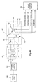
- a power assist steering system 10 includes a steering wheel 12 operatively connected to a pinion gear 14. Specifically, the vehicle steering wheel 12 is connected to an input shaft 16 and the pinion gear 14 is connected to a pinion shaft 17. The input shaft 16 is operatively coupled to the pinion shaft 17 through a torsion bar 18. The torsion bar 18 twists in response to applied steering torque thereby permitting relative rotation between the input shaft 16 and the pinion shaft 17. Stops of a type well known in the art limit the amount of such relative rotation between the input and pinion shafts.
- the pinion gear 14 has helical teeth which are meshingly engaged with straight cut teeth on a rack or linear steering member 20.
- the pinion gear in combination with the straight cut gear teeth on the rack member form a rack and pinion gear set.
- the rack is steerably coupled to the vehicle's steerable wheels 22, 24 with steering linkage in a known manner.
- the rack and pinion gear set converts the rotary motion of the steering wheel into linear motion of the rack.
- the steerable wheels 22, 24 pivot about their associated steering axis and the vehicle is steered.
- An electric assist motor 26 is drivingly connected to the rack 20. When the electric motor 26 is energized, it provides power assist so as to aid in the rotation of the vehicle steering wheel by the vehicle operator.
- the electric assist motor is a variable reluctance motor.
- a variable reluctance motor is desirable for use in an electric assist steering system because of its small size, low friction, and its high torque-to-inertia ratio.
- the rack 20 has a straight rack tooth portion 28 in meshing engagement with the pinion gear.
- the rack 20 also has a threaded convolution portion 30.
- the variable reluctance motor 26 circumscribes the rack 20 and is mounted in a motor housing 32.
- the motor 26 includes a plurality of stator windings 34, each one wrapped about its associated stator pole 36.
- the motor 26 also includes a rotor 38 having a plurality of rotor poles 40.
- the variable reluctance motor includes eight stator poles and six rotor poles. The stator poles are arranged so as to be energizes in pairs designated Aa, Bb, Cc, and Dd.
- variable reluctance motor The operation of a variable reluctance motor and its principle of operation are well known in the art. Basically, the stator poles are energized in pairs. The rotor moves so as to minimize the reluctance between the stator poles and the rotor poles. Minimum reluctance occurs when a pair of rotor poles are aligned with the energized stator poles. Once minimum reluctance is achieved, i.e., when rotor poles align with a pair of energized stator coils, those energized stator coils are de-energized and an adjacent pair of stator coils are energized. The direction of motor rotation is controlled by the sequence in which the stator coils are energized. The torque produced by the motor is controlled by the current through the stator coils.
- U.S. Patent No. 5,257,828, to Miller et al., and assigned to TRW Inc discloses a control arrangement for variable reluctance motor.
- the motor 26 is mounted in the motor housing 32 and rotatably supports the rack 20 through bearings 42, 44.
- the rack is also supported by the pinion gear and bearing 45.
- the motor rotor is drivingly connected to a ball-nut drive arrangement 46 through a connection tube 48.
- the ball-nut drive arrangement 46 circumscribes the threaded convolution portion 30 of the rack 20 with the nut portion being operatively connected to the threaded convolution portion of the rack through a plurality of balls 47.
- the motor When the motor is energized, the rotor turns which, in turn, rotates the nut portion of the ball-nut drive arrangement. When the nut rotates, the balls transfer a linear force to the rack. The direction of rack movement is dependent upon the direction of rotation of the motor.
- the nut 46 is rotatably supported in the housing 32 by thrust bearings 50, 52.
- a motor position sensor 54 is operatively connected between the motor rotor and to the motor stator.
- the function of the motor position sensor 54 is to provide an electrical signal indicative of the position of the rotor relative to the stator. For proper operation of the variable reluctance motor, including direction of rotation and applied torque, it is necessary to know the position of the rotor relative to the stator.
- a physical rotor position sensor is provided. It is known in the art that the rotor position can be determined by means other than a physical position sensor. For example, it is possible to monitor the current through the de-energized stator coils and, based upon the sensed current, the rotor position is determined.
- One specific arrangement for sensing rotor position without a separate position sensor is disclosed in U.S. Patent No. 5,072,166.
- the rotor position sensor 54 includes a transmitting ring 56 and a receiving ring 58.
- the rings shown in Fig. 4 are axially offset for clarity. In their assembled position, shown in Fig. 5, the rings are mounted so as to be concentric (nested) about a common axis 60.
- the rings 56, 58 are preferably made from a magnetically permeable material that will support magnetic flux in the 200 kHz frequency range. The permeability of such material preferably exceeds 10 at this frequency. Magnetically permeable materials that exhibit such characteristics include powdered iron, soft ferrites, and ferrite filled plastic.
- the magnetically permeable material provides a return path for the magnetic circuits associated with the transmitting and receiving rings.
- the magnetically permeable material provides filtering of EMF interference from outside sources, and even from the operation of the motor itself.
- the transmitting ring 56 has an outer diameter d1.
- the receiving ring 58 has an inner diameter d2.
- the diameter d1 is less than the diameter d2 so that a relatively small air gap exists between the two rings when they are assembled in their concentric or nested arrangement.
- the transmitting ring 56 is coaxially secured to the rotor 38.
- the transmitting ring 56 has two sinusoidal grooves 62a and 62b cut in its outer surface 64.
- the sinusoidal grooves 62a and 62b are 180 electrical degrees out of phase.
- the orientation of the grooves 62a and 62b are referred to as being a circumferentially varying sinusoidal pattern.
- a transmitting coil 66 is disposed in the grooves 62a and 62b around the entire circumference of the ring 56.
- the transmitting coil 66 comprises two conductive electrical tracks 68a and 68b being disposed in the grooves 62a and 62b, respectively.
- the conductive electrical tracks 68a and 68b are electrically insulated from each other and from the ring 56.
- the depth of the grooves 62a and 62b and the dimension of the conductors 68a and 68b are such that, once assembled, the conductors 68a and 68b are flush with the outer surface 64.
- Each conductive electrical track 68a and 68b is arranged in a circumferentially varying sinusoidal pattern, with a 180° relative offset between the two patterns.
- the number six is the spatial frequency of the patterns, with each pattern undergoing a 360° phase change every sixty mechanical degrees.
- the patterns repeat every sixty mechanical degrees, corresponding to the number of rotor poles 40 of the motor 26.
- Figs. 7A and 7B depict a scale of mechanical degrees of the ring 56 and a scale of electrical degrees of the ring 56, respectively.
- Fig. 7C illustrates the sinusoidal patterns of the conductive electrical tracks 68a and 68b.
- the two conductive electrical tracks 68a and 68b have first connection terminals 72 and 74, respectively.
- a common connection terminal 76 joins the other connection terminal of the tracks.
- the instantaneous current in conductive electrical track 68a is in a direction opposite to that in track 68b.
- the effect of the two circumferentially varying sinusoidal patterns is a well defined instantaneous magnetic flux pattern of alternating positive and negative potentials in the respective areas bounded by the two conductor patterns.
- the transmitting ring 56 is made from a powdered iron toroid.
- the two grooves 62a and 62b are machined in the outer surface 64 of the toroid to form the sinusoidal patterns previously described.
- a wire is laid in each of the grooves to form the conductive electrical tracks 68a and 68b.
- the grooves 62a and 62b are slightly tapered in an inward radial direction to hold the wires therein.
- an adhesive is applied to secure the wires in place.
- One of the groove depths is greater than the other to avoid pressure at the intersection points of the two wires. In this embodiment, it is desirable to keep the wires as close to the surface of the ring 56 as possible to assure a well-defined magnetic pattern is transmitted.
- the transmitting ring 56 includes conductors 68a and 68b secured to the outer surface 64 of the ring 56 in the sinusoidal pattern through electroplating, plasma deposition, sputtering methods, or other similar techniques known to those skilled in the art.
- the deposition of the conductors in this embodiment must be done sequentially.
- An insulating layer must first be deposited on the ring 56, followed by one of the sinusoidal conductor patterns, then a second insulating layer, and finally the second sinusoidal conductor pattern.
- a single layer deposition can be used if an insulated bridge is provided for one of the sinusoidal conductors at each of the intersections or cross over locations between the two conductors.
- Another alternative embodiment of the transmitting ring 56 utilizes a two layer flexible linear circuit.
- the sinusoidal pattern is created on a two layer flexible linear circuit board having a mean length which fits around the circumference of the ring 56.
- the flexible linear circuit is then bonded to the outer surface 64 of the ring 56 using adhesive methods known to those skilled in the art.
- the transmitting ring 56 is made of a moldable soft ferrite material with a plurality of radially raised, foot-ball shaped, lands or bobbins.
- the radially raised bobbins form a border for sinusoidal patterns similar to the patterns described above.
- Each radially raised bobbin is referred to as a pole.
- An insulated wire is wound around the poles in a first direction, following a sine pattern, around the entire circumference of the ring.
- the insulated wire is then wound around the poles in the other direction following a 180° shifted sine pattern to the original starting terminal.
- the number of windings of the insulated wire may be repeated to yield an increased turns ratio.
- the outer diameter of the raised pole ring must be less than the inner diameter of a receiving ring to insure an air gap between the transmitting ring and the receiving ring.
- the raised pole design allows for manufacture through low cost molding techniques, and is readily producible in large volumes.
- the raised poles also allow for the use of conventional winding techniques in mounting the wire on the transmitter ring thereby resulting in further cost advantages.
- the raised poles provide a magnetically focused field area and, therefore, improve the efficiency of the transmitting ring.
- the receiving ring 58 is mounted to the motor stator and, in turn, to the housing 32 in a coaxial relationship with the transmitting ring 56 so that the transmitting ring 56 is nested inside of the receiving ring 58.
- the radial proximity of the ring 56 and ring 58 provides electromagnetic coupling therebetween so as to form a rotary transformer 78.
- the receiving ring 58 has a plurality of parallel conductive tracks 80 cut into its inner surface 82.
- a plurality of receiving coils 84 are wound in these tracks.
- the receiving coils 84 in accordance with one embodiment of the present invention, comprises three sets of coils each of which are wound in associated tracks 86a, 86b, and 86c with each of the coils being insulated from one another and from the ring 58.
- the coils are also designated 86a, 86b, and 86c, respectively.
- Each of the tracks 86a, 86b, and 86c is arranged in a circumferentially varying square wave pattern, separated from each of the other patterns by thirds so as to be offset by 120° electrical degrees (20° mechanical) from the other two patterns. Every sixty mechanical degrees, the patterns repeat.
- FIGs. 7D, 7E, and 7F the outputs of each of the coils in tracks 86a, 86b, and 86c are depicted. These coils form square wave patterns 86a, 86b, 86c, respectively.
- the coil in track 86a has a connection terminal 88.
- the coils in tracks 86b and 86c have, respectively, connection terminals 90 and 92.
- the coils in tracks 86a, 86b, and 86c have a common connection terminal 94.
- the slots 80 are circumferentially narrow and radially shallow to assure a sharp delineation of the magnetic field transmitted by the transmitting ring 56.
- the coils 86a, 86b, and 86c are each made with wire positioned in the slots 80 with a wire being placed in every third slot.
- the wire for coil 86a is placed in one slot 86a, runs along the edge of ring 58 until it reaches the next slot 86a where it runs up that next slot.
- the wire 86a in effect, forms a square wave pattern in slots 56a around the entire circumference of ring 58.
- the wires in the slots relative to the transmitter windings is shown in Figs 7D-7F.
- the wire pattern shown in Fig. 7G can be used for each of the tracks.
- the dotted line corresponds to a return wire and effectively increases the turns ratio of the coil formed by the wire, thereby increasing the strength of the signal received by that coil.
- the signal from the receiving coils 86 is accessible though stationary contacts 88, 90, 92 since the receiving ring 58 is secured to the stator. Since the transmitting ring 56 is secured to the rotor 38, the coil 68 is energized through a rotary transformer arrangement 95 (as shown in Fig. 8).
- a primary coil 96 is secured to the stator 32 and is electrically connected through terminals 97, 98.
- a secondary coil 99 is secured to the rotor 38 and is electrically connected to the transmitting coil 68 through terminals 72, 74 (Fig. 6). The primary coil 96 and secondary coil 99 are in sufficiently close proximity to each other so as to form the rotary transformer 95.
- the primary coil 96 is electrically connected to a signal generator 100 through a primary drive circuit 101.
- the drive signal applied to the rotary transformer 95 is a sinusoidal drive signal.
- the receiving coil 99 outputs a sinusoidal signal in response to the electromagnetic field transmitted by the transmitting coil 96.
- the transmitting coil 68 of the transmitting ring 56 is, in turn, driven with the 200 kHz sinusoidal drive signal.
- the receiving coils 86a, 86b, 86c each output a sinusoidal signal.
- the sinusoidal signals from the receiving coils 86a, 86b, 86c are offset from each other by 120 electrical degrees.
- the equations represent the value of the voltage present across the associated coil.
- the voltage V1 is the voltage across the coil 86a
- V2 and V3 are the voltages across the coils 86b and 86c, respectively.
- each receiving coil 86 goes through six cycles (360 electrical degrees) for each 360 mechanical degrees of relative rotation between the transmitting ring 56 and the receiving ring 58, or, equivalently, between the rotor and the stator. If the output of each receiving coil were to be observed, the output voltage amplitudes would follow a sine wave pattern and end at its starting terminal each 1/6th of a complete mechanical revolution between the stator and the rotor. Therefore, the voltage at the output of each receiving coil goes through 360 electrical degrees for each 60 degrees of mechanical rotation between the rotor and the stator.
- the equations for V1, V2, and V3 provide three equations with three unknowns.
- a controller 150 monitors the values output by each of the receiving coils 84.
- the controller 150 is preferably a microprocessor or microcomputer. At any instant in time t, the controller 150 can measure the value of the voltage present at the outputs of the receiving coils and solve the equations for ⁇ .
- the solution of the equations for ⁇ represents the rotary position of the motor rotor relative to the stator. Knowing the position of the rotor relative to the stator permits the controller 150 to control commutation of the motor 26.
- a position sensor 103 is operatively connected across the input shaft 16 and the pinion shaft 17 and provides an electrical signal having a value indicative of the relative rotational position between the input shaft and the pinion shaft.
- the position sensor 103 in combination with the torsion bar 18 form a torque sensor 110.
- the output of the position sensor is indicative of the applied steering torque to the vehicle steering wheel 12 by the vehicle operator.
- the output of the torque sensor 110 is connected to an assist function circuit 111 that provides a desired torque value as a function of applied steering torque measured by the torque sensor 110.
- This functional relationship may be any one of several possible relationships with the goal of improving steering feel.
- one functional relationship contemplated between the output of 111 and the input of applied steering torque is a "smile" curve.
- Other contemplate relationships include those disclosed in EP 0 683 086 A1 (US 5 504 403A to McLaughlin Serial No. 246,947 filed May 20, 1994) and EP 0 671 310 A1 (US 5 568 389 A to McLaughlin et al. Serial No. 212,112 filed March 11, 1994).
- the output of the assist function circuit 111 is connected to a lead/lag filter 112.
- the lead/lag filter 112 processes the torque signal and separates it into a direction signal 114 and a magnitude signal 116. In processing the torque signal, the lead/lag filter 112 amplifies the value of torque signal.
- the torque magnitude value 116 is converted to a torque command signal preferably by use of a torque look-up table 118 based upon the corque magnitude.
- a torque look-up table 118 based upon the corque magnitude.
- filtering of the output of the torsion sensor signal may be distributed differently about the torque command table than is specifically shown and described.
- the output of the assist function circuit 111 may be directly connected to the table 118 and the filtering occurring at the output of the table.
- a vehicle speed sensor 119 is operatively connected to the vehicle and has an output 129.
- Speed sensor 119 provides a signal, hereinafter referred to as "s", having a value indicative of the vehicle's speed.
- Output 129 is operatively connected to a speed fold-back circuit 121 and a damping control circuit 220.
- a vehicle speed sensor includes a device connected to the vehicle wheels or to the vehicle transmission that generates pulses at a frequency that is a function of the vehicle speed.
- the speed sensor further includes circuitry that converts the pulse frequency into a signal having a value indicative of the vehicle speed.
- the output 129 of speed sensor 119 and the output from the torque command table 118 are combined in speed fold-back circuit 121.
- the output 126 of the speed fold-back circuit is a torque command signal that is "corrected" as a function of vehicle speed.
- the output 126 is connected to a soft start control circuit 130.
- the soft start control circuit 130 is also operatively connected to the vehicle ignition switch 132 for detection of when the vehicle is first started.
- the purpose of the soft start control circuit is to prevent full assist from being provided to the vehicle the instant the vehicle is being started. It is not uncommon for the vehicle operator to be applying torque to the steering wheel with one hand while he is turning the ignition switch to the starting position. If full power assist were immediately available, the steering wheel would jerk in his hand.
- the soft start circuit prevents this unpleasant event from happening and simulates the operation of a hydraulic power assist steering system which does not provide full power assist until the vehicle motor is running at speed (as opposed to cranking speed).
- the output of the soft start circuit is the torque demand or request signal "corrected" for vehicle speed.
- the output of the soft start circuit is connected to a thermal and current fold-back circuit 138.
- a system temperature sensor circuit 180 monitors temperature of the circuitry used to control the electric assist motor 26.
- a motor current sensor 190 monitors current through the motor and outputs a signal to the thermal and current fold-back circuit 138 indicative of the sensed current through the motor 26.
- the thermal and current fold-back circuit 138 further modifies the torque request signal as a function of the sensed current through the motor and the sensed temperature of the control circuitry.
- the output of the fold-back circuit 138 is connected to the torque command and direction circuit 140.
- the direction signal 114 is also connected to the torque command and direction circuit 140.
- the circuit 140 recombines the torque direction signal with the torque request signal that has been "corrected" for (i) vehicle speed, (ii) soft start, (iii) sensed motor current, and (iv) sensed temperature of the control circuitry.
- the output of the torque command and direction circuit 140 is connected as one input of a summing circuit 142.
- the output of the torque command and direction circuit 140 is also connected as one input of a damping control circuit 220.
- the output of the summing circuit 142 is connected to the input of a drive control circuit 150.
- the output of the motor position sensor 54 is also connected to the drive control circuit 150.
- the drive control circuit 150 Based upon the torque command signal output from the summing circuit 142 and based upon the position of the rotor, the drive control circuit 150 provides a motor control signal used to control energization of the electric assist motor 26 in terms of sequence and current applied to the stator coils through a plurality of power switches 154.
- the drive control circuit 150 is preferably is a microcomputer. Commutation or drive pulses may need to be output to the stator windings at a rate faster than the motor position data can be processed from the sensor 54 to insure smooth operation of the variable reluctance motor.
- the position of the rotor can be estimated at predetermined times between actual rotor position measurements based upon certain known conditions and certain assumptions. Rotor position estimation is described in an IEEE paper entitled “A Simple Motion Estimator For VR Motors" by W.D. Harris and J.H. Lang, IEEE Industry Applications Society Annual Meeting, October 1988 and in a paper entitled “A State Observer for Variable Reluctance Motors: Analysis and Experiments" by A Lumsdaine, J.H. Lang, and M.J. Balas, 19th ASILOMAR Conference on Circuits, Systems & Computers, November 6-8, 1985.
- a typical drive circuit is shown for a pair of the stator coils Aa. Each of the other motor phases have similar drive circuits.
- the first drive switch 160 is operatively connected between one side of the stator coil and electrical ground.
- a second drive switch 161 is connected to the other side of the coil pair Aa through a current sense resistor 162. The other side of the switch 161 is connected to the vehicle battery through an LC filter network 162.
- a first fly-back diode 163 is connected between one terminal of the motor and the LC filter 162.
- a second fly-back diode 164 is connected between ground and the switch 161.
- An over-voltage protection Zener diode 165 is connected across switch 161.
- An over-voltage protection Zener diode 166 is connected across switch 160.
- switches 160, 161 are solid state switches such as field-effect-transistors ("FET's"). Current control is accomplished by the drive control circuit 150 pulse-width-modulating ("PWM”) the switches 160, 161 on control lines 166, 167.
- PWM pulse-width-modulating
- the output from the rotor position sensor 54 is also connected to a motor velocity sensor circuit 200.
- the change in the rotor position as a function of time is indicative of the rotor and, in turn, the motor velocity.
- the output of the motor velocity sensing circuit 200 is an electric signal having a value indicative of the motor speed and sign, i.e. direction, of rotation.
- a tachometer connected to the rotor or a curve fitting arrangement using look-up tables.
- Motor velocity sensor 200 has an output 201 connected to (i) damping control circuit 220 and (ii) a multiplier circuit 210.
- the output 201 of sensor 200 provides a signal, hereinafter also referred to as W m , indicative of motor velocity.
- the motor velocity signal W m has both a magnitude component and a direction of rotation component.
- Damping control circuit 220 has an output 221 which provides a damping control signal, hereinafter also referred to as K D .
- the damping control signal K D has a value functionally related to the value of the sensed motor velocity and the value of the sensed vehicle speed.
- the output 221 of damping control circuit 220 is connected as a second input of multiplier circuit 210.
- Multiplier circuit 210 has an output 211 and provides a retarding torque signal, hereinafter also referred to as R ⁇ .
- Retarding torque signal R ⁇ is functionally related to damping control signal K D and motor velocity signal W m .
- the retarding torque R ⁇ value output from the multiplier 210 is the negative input to the summing circuit 142.
- a non-linear function of retarding torque is depicted in accordance with one embodiment of the invention.
- the resultant damping term output from the multiplier 211 is low.
- the resultant damping output value from the multiplier 211 increases.
- the damping value increases in an increasing parabolic fashion.
- damping is the amount of retarding force which opposes the electric assist motor rotation. If the damping is equal to zero, there is no retarding torque applied to the electric assist motor. Without retarding torque applied to the electric assist motor, there is less resistance to turning the steerable wheels or returning the steerable wheels to the straight-ahead position after a turning maneuver. If the vehicle is traveling at a high rate of speed and the damping is zero, the vehicle may become unstable resulting in increasing yaw rate of the vehicle and "spinning-out.”
- the damping of the vehicle yaw by control of the electric assist steering is functionally related to both the sensed vehicle speed and the sensed velocity of the power assist motor in a non-linear manner.
- the output 201 from sensor circuit 200 is providing a signal value indicative of how fast the steerable wheels are turning in a turning maneuver or returning to the straight-ahead position after a turning maneuver. The faster the steerable wheels are turning or returning toward center, the greater the damping.
- other damping coefficient calibration may be desirable for good "feel.”
- the amount of retarding torque R ⁇ applied to the assist motor may vary depending on the desired "steering feel" of the vehicle. For example, a different "steering feel" or retarding torque may be desired for a turning maneuver than the "steering feel” or retarding torque during a return of the steerable wheels to a straight-ahead position.
- applied steering torque versus motor torque is divided into four quadrants.
- the X-axis shows the direction of motor torque.
- the Y-axis shows the direction of the steering torque applied to the steering wheel.
- Positive values for both direction of motor torque and direction of applied steering torque defines Quadrant I.
- a negative value for the direction of motor torque and a positive value for the direction of steering torque defines Quadrant II.
- Negative values for both motor torque and direction of applied steering torque defines Quadrant III.
- a positive value for the direction of motor torque and a negative value for applied steering torque defines Quadrant IV.
- Different values of retarding torque may be desired depending upon which quadrant the power assist steering system 10 is operating. For example, when the vehicle power assist steering system 10 is operating in Quadrants I and III, lower damping may be desired. This is because damping is a retarding torque which decreases the assist provided by the electric assist motor. Greater assist is desired during a turning maneuver than during a return of the steerable wheels to a straight-ahead position. When the power assist steering system 10 is operating in Quadrants II and IV, indicating a return of the steerable wheels to a straight-ahead position, higher damping may be desired. This is because the retarding torque stabilizes yaw rate, as described above.
- the different levels of retarding torque may be obtained by providing more than one look-up table having values for the constants A 1 , A 2 , B 1 , and B 2 .
- a first table, having values for the constants A 1 , A 2 , B 1 , and B 2 may be provided when the power assist steering system is operating in Quadrants I and III.
- a second table, having relatively higher values for the constants than the values in the first table may be provided when the system is operating in Quadrants II and IV.
- the higher values for the constants A 1 , A 2 , B 1 , and B 2 provides higher damping factors and increases the retarding torque applied to the assist motor.
- step 300 the steering torque direction is determined.
- Torque command and direction circuit 140 provides the applied steering torque direction to damping control circuit 220.
- step 302 direction of motor torque is determined.
- Motor velocity sensor 200 provides a signal to damping control circuit 220 indicating the direction of rotation of motor 26. It will be appreciated that velocity has both a magnitude component and a direction component. The direction of rotation of motor 26 is functionally related to the direction of movement of the steerable wheels. The process then proceeds to step 304.
- step 304 a determination is made in damping control circuit 220 as to which quadrant the power assist steering system 10 is operating.
- step 306 a determination is made as to whether the power assist steering system is operating in Quadrants I or III. If the determination in step 306 is affirmative, i.e. the power assist steering system is engaged in a turning maneuver and is operating in either Quadrant I or III, the process proceeds to step 308.
- step 308 the first table of values for constants A 1 , A 2 , B 1 , and B 2 is selected to determine the values of the damping factors K d1 (s), the vehicle speed damping factor, and K d2 (W m ), the assist motor velocity damping factor. The process then returns to step 300.
- step 306 determines whether the determination in step 306 is negative, i.e. the power assist steering system is engaged in a return of the steerable wheels to a straight-ahead position and is operating in either Quadrant II or IV.
- the process proceeds to step 310.
- the second table of values for constants A 1 , A 2 , B 1 , and B 2 is selected to determine the values of the damping factors K d1 (s), the vehicle speed damping factor, and K d2 (W m ), the assist motor velocity damping factor.
- the process then returns to step 300.
- damping in accordance with the present invention, is non-linear.
- the present arrangement not only simulates the feel of a hydraulic assist system at low speeds, it provides an improved handling stability at all vehicle speeds, especially at speeds greater than 55 mph or less than 10 mph.
- the control arrangement depicted in Fig. 1 shows modification of the torque signal in summing circuit 142 by the values of (i) the damping from circuit 220 (vehicle speed "s" and motor velocity W m ) and (ii) motor velocity W m from motor velocity sensor 200. Modifying the torque signal results in modifying the motor control signal output of the drive control circuit 150.
- Fig. 1 may be embodied in discrete circuitry, a microcomputer, or in an application specific integrated circuit ("ASIC").
- ASIC application specific integrated circuit
Landscapes
- Engineering & Computer Science (AREA)
- Chemical & Material Sciences (AREA)
- Combustion & Propulsion (AREA)
- Transportation (AREA)
- Mechanical Engineering (AREA)
- Power Steering Mechanism (AREA)
- Steering Control In Accordance With Driving Conditions (AREA)
Claims (10)
- Elektrisches Hilfskraftlenksystem 10, das Folgendes aufweist:Drehmoment-Sensormittel 110 zum Abfühlen des angelegten Lenkdrehmoments und zum Liefern eines Lenkdrehmoment-Signals ansprechend darauf;Mittel 111, 112, 114, 118 zum Liefern eines Drehmoment-Anforderungssignals mit einem Wert, der funktionsmäßig mit dem angelegten Lenkdrehmoment im Beziehung steht;einen elektrischen Hilfsmotor 26, betriebsmäßig verbunden mit einem Lenkglied 20, um dann, wenn erregt, eine Hilfskraftlenkung vorzusehen;Mittel 150, 154 zum Liefern eines Motorsteuer-Signals ansprechend auf das Drehmoment-Anforderungssignal; undMotordrehzahl-Sensormittel 200 zum Abfühlen der Drehzahl des elektrischen Hilfsmotors 26 und zum Liefern eines Motordrehzahl-Signals Wm; 201, welches eine Anzeige dafür bildet;wobei das System Folgendes aufweist:
Verarbeitungsmittel 220, 210 zur Verarbeitung des Motordrehzahl-Signals (Wm)(201) mit einem Signal KD, was eine Funktion des Motordrehzahl-Signals Wm selbst ist zur Erzeugung eines nicht linearen Motordrehzahl-Signals 211 und Signalmodifiziermittel 220, 210 zum Modifizieren des Motorsteuer-Signals ansprechend auf das nicht lineare Motordrehzahl-Signal 211, derart, dass eine nicht lineare Dämpfung der durch den elektrischen Hilfsmotor 26 vorgesehenen Hilfskraft als eine Funktion des Motordrehzahl-Signals vorgesehen wird. - System 10 nach Anspruch 1, wobei der elektrische Hilfsmotor 26 ein eine variable Reluktanz besitzender Motor ist.
- System 10 nach Anspruch 1, wobei der Motor 26 einen Rotor 38 und einen Stator 34, 36 aufweist und wobei ferner die Motordrehzahl-Abfühlmittel 200 Mittel 54 aufweisen, um eine relative Position zwischen Rotor 38 und Stator 34, 36 abzufühlen.
- System 10 nach Anspruch 3, wobei die Motordrehzahl-Abfühlmittel 200 ferner Mittel aufweisen zum Abfühlen einer Drehrichtung des Motors 26 und wobei die Modifiziermittel 210, 220 ferner das Motorsteuer-Signal ansprechend auf die abgefühlte Richtung modifizieren.
- System 10 nach einem der vorhergehenden Ansprüche, wobei ferner Folgendes vorgesehen ist:Fahrzeugdrehzahl-Abfühlmittel 119, zum Liefern eines elektrischen Signals 129 mit einem Wert, der die Fahrzeugdrehzahl angibt;wobei die Mittel 121, 150, 154, die ein Motorsteuer-Signal ansprechend auf das Drehmoment-Anforderungssignal auch auf die abgefühlte Fahrzeugdrehzahl (5) ansprechen,wobei die Signalmodifiziermittel 210, 220, 142 das Motorsteuer-Signal modifizieren, und zwar ansprechend auf das nicht lineare Motordrehzahl-Signal und die abgefühlte Fahrzeugdrehzahl der Hilfskraftlenkung, vorgesehen durch den elektrischen Hilfsmotor, um so eine nicht lineare Dämpfung als Funktion des erwähnten nicht linearen Motordrehzahl-Signals Wm und der abgefühlten Fahrzeuggeschwindigkeit(en) für die Fahrzeug-Gierratensteuerung während eines Lenkmanövers vorzusehen.
- System 10 nach Anspruch 5, wobei die Signalmodifiziermittel 210, 220, 142 zum Modifizieren des Motorsteuer-Signals ferner Mittel aufweisen, zur Erhöhung der Dämpfung, wenn die Fahrzeugdrehzahl(en) ansteigen.
- System 10 nach Anspruch 5, wobei der Elektromotor 26 einen Rotor 38 und einen Stator 34, 36 aufweist und wobei die Motordrehzahl-Abfühlmittel 200 ferner Mittel 54 aufweisen zum Abfühlen einer Drehrichtung des Rotors 38, wobei die Signalmodifiziermittel 210, 220, 142 ferner das Motorsteuer-Signal modifizieren, und zwar ansprechend auf die abgefühlte Richtung.
- Verfahren zum Steuern eines elektrischen Hilfskraftlenksystems 10, wobei die folgenden Schritte vorgesehen sind:Abfühlen des angelegten Lenkdrehmoments und Liefern eines Lenkdrehmoment-Signals ansprechend darauf;Vorsehen eines Drehmoment-Anforderungssignals mit einem Wert, der funktionsmäßig mit dem angelegten Lenkdrehmoment in Beziehung steht;Vorsehen eines elektrischen Hilfsmotors 26, betriebsmäßig verbunden mit einem Lenkglied 20, um dann, wenn erregt, eine Hilfkraftlenkung vorzusehen;Vorsehen eines Motorsteuer-Signals ansprechend auf das Drehmoment-Anforderungssignal zur Steuerung des Motors 26;Abfühlen der Drehzahl des elektrischen Hilfsmotors 26 und Vorsehen eines Motordrehzahl-Signals Wm, welches eine Anzeige dafür bildet;Verarbeiten des Motordrehzahl-Signals Wm mit einem Signal, welches eine Funktion des Motordrehzahl-Signals Wm selbst ist, um so ein nicht lineares Motordrehzahl-Signal vorzusehen, undModifizieren des Motorsteuer-Signals mit dem nicht linearen Motordrehzahl-Signal, um so eine nicht lineare Dämpfung der durch den elektrischen Hilfsmotor 26 vorgesehenen Hilfskraftlenkung vorzusehen.
- Verfahren nach Anspruch 8, wobei ferner die folgenden Schritte vorgesehen sind:Abfühlen der Fahrzeuggeschwindigkeit(en) zum Liefern eines elektrischen Signals, welches einen eine Anzeige für die Fahrzeuggeschwindigkeit bildenden Wert besitzt;Vorsehen des Motorsteuer-Signals ansprechend auf das Drehmoment-Anforderungssignal und die abgefühlte Fahrzeuggeschwindigkeit(en) zur Steuerung des Motors 26; undModifizieren des Motorsteuer-Signals ansprechend auf das nicht lineare Motordrehzahl-Signal und die abgefühlte Fahrzeuggeschwindigkeit(en), um so eine nicht lineare Dämpfung der Lenkkraftunterstützung, vorgesehen durch den Motor, also eine nicht lineare Funktion des nicht linearen Motordrehzahl-Signals und der abgefühlten Fahrzeuggeschwindigkeit(en) für die Fahrzeug-Gierratensteuerung während des Lenkmanövers vorzusehen.
- Verfahren nach Anspruch 8, wobei der Schritt des Vorsehens eines elektrischen Hilfsmotors das Vorsehen eines elektrischen Hilfsmotors 26 mit variabler Reluktanz umfasst, und zwar betriebsmäßig verbunden mit dem Lenkglied 20, um dann, wenn erregt, Hilflenkkraft für das Lenkglied vorzusehen,wobei der eine variable Reluktanz besitzende Motor 26 einen Stator 34, 36 und einen Rotor 38 aufweist;wobei der Schritt des Vorsehens eines Motorsteuer-Signals das Vorsehen eines Motorsteuer-Signals ansprechend auf den Wert des Drehmoment-Anforderungssignal umfasst, und zwar zur Steuerung des eine variable Reluktanz besitzenden Motors 26.
Applications Claiming Priority (2)
| Application Number | Priority Date | Filing Date | Title |
|---|---|---|---|
| US331962 | 1994-10-31 | ||
| US08/331,962 US5623409A (en) | 1994-10-31 | 1994-10-31 | Method and apparatus for non-linear damping of an electric assist steering system for vehicle yaw rate control |
Publications (2)
| Publication Number | Publication Date |
|---|---|
| EP0709277A1 EP0709277A1 (de) | 1996-05-01 |
| EP0709277B1 true EP0709277B1 (de) | 2001-10-24 |
Family
ID=23296101
Family Applications (1)
| Application Number | Title | Priority Date | Filing Date |
|---|---|---|---|
| EP95112307A Expired - Lifetime EP0709277B1 (de) | 1994-10-31 | 1995-08-04 | Elektrisches Hilfskraftlenksystem und Verfahren zum Steuern eines solchen Systems |
Country Status (5)
| Country | Link |
|---|---|
| US (1) | US5623409A (de) |
| EP (1) | EP0709277B1 (de) |
| JP (1) | JP2791299B2 (de) |
| BR (1) | BR9504526A (de) |
| DE (1) | DE69523406T2 (de) |
Families Citing this family (62)
| Publication number | Priority date | Publication date | Assignee | Title |
|---|---|---|---|---|
| JPH08282510A (ja) * | 1995-04-17 | 1996-10-29 | Koyo Seiko Co Ltd | パワーステアリング装置 |
| GB9600549D0 (en) * | 1996-01-11 | 1996-03-13 | Lucas Ind Plc | Motor drive control |
| US6032755A (en) * | 1996-01-30 | 2000-03-07 | Trw Inc. | Method and apparatus for compensating torque steer |
| JP2852640B2 (ja) * | 1996-04-12 | 1999-02-03 | 光洋精工株式会社 | 電動パワーステアリング装置 |
| JP4095124B2 (ja) * | 1996-06-19 | 2008-06-04 | 株式会社ジェイテクト | 電動パワーステアリング装置 |
| JPH1095354A (ja) * | 1996-09-24 | 1998-04-14 | Mitsuba Corp | 電気式動力操舵装置 |
| US5992556A (en) * | 1997-04-15 | 1999-11-30 | Trw Inc. | Method and apparatus for damping control of an electric assist steering system with vehicle speed signal loss feature |
| JP3311271B2 (ja) * | 1997-07-01 | 2002-08-05 | 本田技研工業株式会社 | 車両の操舵制御装置 |
| US5988005A (en) * | 1997-07-04 | 1999-11-23 | Mitsuba Corporation | Electric power steering unit |
| US6246197B1 (en) * | 1997-09-05 | 2001-06-12 | Mitsubishi Denki Kabushiki Kaisha | Electric power steering controller |
| US6122912A (en) * | 1997-10-16 | 2000-09-26 | Techco Corporation | Electro-hydraulic power steering systems having improved efficiency |
| JP3652142B2 (ja) * | 1998-11-10 | 2005-05-25 | 光洋精工株式会社 | パワーステアリング装置 |
| US6173223B1 (en) | 1999-01-05 | 2001-01-09 | Ford Global Technologies, Inc. | Steering control method for providing variable assist power steering |
| US6167334A (en) * | 1999-01-05 | 2000-12-26 | Ford Global Technologies, Inc. | Method and apparatus for providing variable assist power steering |
| RU2158692C2 (ru) * | 1999-01-06 | 2000-11-10 | Общество с ограниченной ответственностью Научно-производственное предприятие "Эметрон" | Электроусилитель руля автомобиля |
| RU2162041C2 (ru) * | 1999-01-06 | 2001-01-20 | Общество с ограниченной ответственностью Научно-производственное предприятие "Эметрон" | Сервопривод с малыми пульсациями момента |
| US6098741A (en) * | 1999-01-28 | 2000-08-08 | Eaton Corporation | Controlled torque steering system and method |
| KR100308385B1 (ko) * | 1999-02-10 | 2001-09-26 | 밍 루 | 차량용 동력 조향장치의 반력장치 |
| US6295879B1 (en) * | 1999-03-08 | 2001-10-02 | Trw Inc. | Torque sensing apparatus for an electric assist steering system |
| US6338016B1 (en) * | 1999-03-08 | 2002-01-08 | Trw Inc. | Method and apparatus for detecting a motor stall condition in an electric assist steering system |
| US6498449B1 (en) | 1999-09-17 | 2002-12-24 | Delphi Technologies, Inc. | Low ripple torque control of a permanent magnet motor without using current sensors |
| WO2001047762A1 (en) | 1999-12-29 | 2001-07-05 | Delphi Technologies, Inc. | Method and system for improving motor vehicle stability incorporating an electric power steering system |
| US6505108B2 (en) * | 2000-03-01 | 2003-01-07 | Delphi Technologies, Inc. | Damper based vehicle yaw control |
| WO2001077812A1 (en) * | 2000-04-07 | 2001-10-18 | Delphi Technologies, Inc. | Damping of voltage-controlled brushless motors for electric power steering systems |
| US6422335B1 (en) | 2000-04-11 | 2002-07-23 | Trw Inc. | Method and apparatus for controlling steering feel with diagnostics |
| JP3843202B2 (ja) * | 2000-06-02 | 2006-11-08 | 株式会社ジェイテクト | 電動パワーステアリング装置 |
| JP2002002514A (ja) * | 2000-06-16 | 2002-01-09 | Unisia Jecs Corp | 電動モータ駆動式操舵補助装置の異常判定装置 |
| EP1170196B1 (de) * | 2000-06-29 | 2008-08-06 | TRW Limited | Verbesserungen in Verbindung mit elektrischen Servolenksystemen |
| JP4524880B2 (ja) * | 2000-08-10 | 2010-08-18 | マツダ株式会社 | 自動車の電動パワーステアリング装置 |
| US6498451B1 (en) | 2000-09-06 | 2002-12-24 | Delphi Technologies, Inc. | Torque ripple free electric power steering |
| US6566829B1 (en) | 2000-09-07 | 2003-05-20 | Delphi Technologies, Inc. | Method and apparatus for torque control of a machine |
| DE60233404D1 (de) | 2001-06-08 | 2009-10-01 | Delphi Tech Inc | Geschwindigkeitsausgleichssteuerung für elektrische lenksysteme |
| US7199549B2 (en) * | 2001-08-17 | 2007-04-03 | Delphi Technologies, Inc | Feedback parameter estimation for electric machines |
| US7071649B2 (en) | 2001-08-17 | 2006-07-04 | Delphi Technologies, Inc. | Active temperature estimation for electric machines |
| US20030076064A1 (en) * | 2001-08-17 | 2003-04-24 | Kleinau Julie A. | Feedforward parameter estimation for electric machines |
| US6900607B2 (en) * | 2001-08-17 | 2005-05-31 | Delphi Technologies, Inc. | Combined feedforward and feedback parameter estimation for electric machines |
| JP4322450B2 (ja) * | 2001-09-04 | 2009-09-02 | 三菱電機株式会社 | 電動式パワーステアリング制御装置 |
| JP4517555B2 (ja) * | 2001-09-14 | 2010-08-04 | マツダ株式会社 | 自動車の電動パワーステアリング装置 |
| EP1759956B1 (de) * | 2001-10-11 | 2008-09-17 | Delphi Technologies, Inc. | Verfahren zur Erzeugung eines Dämpfungsmomentsignals eines Motors einer elektrischen Hilfskraftlenkung |
| US6658335B2 (en) * | 2001-10-11 | 2003-12-02 | Delphi Technologies, Inc. | Method and apparatus for motor velocity measurement compensation in electric power steering damping |
| US7576506B2 (en) | 2001-12-11 | 2009-08-18 | Delphi Technologies, Inc. | Feedforward parameter estimation for electric machines |
| FR2837457B1 (fr) | 2002-03-20 | 2004-06-18 | Renault | Systeme d'assistance electrique de direction avec amortissement pour un vehicule et son procede de commande |
| JP4059003B2 (ja) * | 2002-05-27 | 2008-03-12 | 株式会社ジェイテクト | 電動パワーステアリング装置 |
| US7143864B2 (en) * | 2002-09-27 | 2006-12-05 | Ford Global Technologies, Llc. | Yaw control for an automotive vehicle using steering actuators |
| US7157878B2 (en) * | 2002-11-19 | 2007-01-02 | Delphi Technologies, Inc. | Transient compensation voltage estimation for feedforward sinusoidal brushless motor control |
| US6763293B2 (en) * | 2002-12-11 | 2004-07-13 | Continental Teves, Inc. | Calibration procedure for a permanently powered relative steering wheel angle sensor with power-loss indication |
| US6864662B2 (en) * | 2003-04-30 | 2005-03-08 | Visteon Global Technologies, Inc. | Electric power assist steering system and method of operation |
| JP4242233B2 (ja) * | 2003-08-22 | 2009-03-25 | 富士重工業株式会社 | ステアリング制御装置 |
| DE10351485A1 (de) * | 2003-11-04 | 2005-06-09 | Zf Lenksysteme Gmbh | Fahrzeug-Hilfskraftlenkung mit Elektromotor |
| GB0401965D0 (en) * | 2004-01-30 | 2004-03-03 | Trw Lucasvarity Electric Steer | Method and apparatus for controlling an electric assist motor using a modified blending filter |
| EP1616774A3 (de) | 2004-07-15 | 2007-08-08 | NSK Ltd., | Elektrische Servolenkung |
| US7532966B2 (en) * | 2004-08-20 | 2009-05-12 | General Motors Corporation | Torque steer compensation algorithm |
| US7163080B2 (en) * | 2005-03-11 | 2007-01-16 | Trw Automotive U.S. Llc | Method and apparatus for detecting a failed temperature sensor in an electric assist steering system |
| JP4847060B2 (ja) | 2005-07-15 | 2011-12-28 | 日立オートモティブシステムズ株式会社 | 交流モータ駆動装置及びその制御方法 |
| US20080024028A1 (en) * | 2006-07-27 | 2008-01-31 | Islam Mohammad S | Permanent magnet electric motor |
| US7543679B2 (en) * | 2006-07-28 | 2009-06-09 | Delphi Technologies, Inc. | Compensation of periodic sensor errors in electric power steering systems |
| US7549504B2 (en) * | 2006-07-28 | 2009-06-23 | Delphi Technologies, Inc. | Quadrant dependent active damping for electric power steering |
| US7725227B2 (en) | 2006-12-15 | 2010-05-25 | Gm Global Technology Operations, Inc. | Method, system, and apparatus for providing enhanced steering pull compensation |
| JP4930771B2 (ja) * | 2006-12-19 | 2012-05-16 | 株式会社ジェイテクト | 電動パワーステアリング装置 |
| US8296011B2 (en) | 2007-12-12 | 2012-10-23 | Steering Solutions IP Holding Corporations | Systems and methods involving quadrant dependent active damping |
| US8126612B2 (en) * | 2008-10-27 | 2012-02-28 | Concordia University | Steering system and method for independent steering of wheels |
| US11519757B2 (en) | 2020-06-11 | 2022-12-06 | Honeywell International Inc. | System and method for determining angular position in rotating machines |
Citations (8)
| Publication number | Priority date | Publication date | Assignee | Title |
|---|---|---|---|---|
| US3983953A (en) * | 1971-07-28 | 1976-10-05 | Gemmer-France | Servo mechanism |
| US4415054A (en) * | 1982-08-05 | 1983-11-15 | Trw Inc. | Steering gear |
| US4660671A (en) * | 1985-10-23 | 1987-04-28 | Trw Inc. | Electric steering gear |
| US5072166A (en) * | 1990-06-18 | 1991-12-10 | The Texas A&M University System | Position sensor elimination technique for the switched reluctance motor drive |
| EP0654393A1 (de) * | 1993-11-19 | 1995-05-24 | Koyo Seiko Co., Ltd. | Elektrische Servolenkung |
| EP0671310A1 (de) * | 1994-03-11 | 1995-09-13 | Trw Inc. | Verfahren und Vorrichtung zur Steuerung eines elektrischen Hilfslinkkraftsystems |
| EP0681955A1 (de) * | 1994-05-11 | 1995-11-15 | Trw Inc. | Verfahren und Vorrichtung zur Regelung eines elektrischen Hilfskraftlenksystems mit einem anpassungsfähigen Drehmomentfilter |
| EP0683086A1 (de) * | 1994-05-20 | 1995-11-22 | Trw Inc. | Verfahren und Vorrichtung zur Regelung eines elektrischen Hilfs-Kraftlenksystems mit einem anpassungsfähigen Drehmomentmischfilter |
Family Cites Families (30)
| Publication number | Priority date | Publication date | Assignee | Title |
|---|---|---|---|---|
| US5075608A (en) * | 1974-06-24 | 1991-12-24 | Erdman David M | Control system, electronically commutated motor system, draft inducer apparatus and method |
| US3984953A (en) | 1974-11-22 | 1976-10-12 | Ernest Joseph Kump | Transport configuration for a modular environmental space module |
| US4107595A (en) * | 1977-01-24 | 1978-08-15 | Teletype Corporation | Current control system for a stepping motor |
| JPS60114574A (ja) * | 1983-11-25 | 1985-06-21 | Canon Inc | 放電による堆積膜の製造装置 |
| JPS60154955A (ja) * | 1984-01-25 | 1985-08-14 | Nissan Motor Co Ltd | 電動式動力舵取り装置 |
| JPH0674052B2 (ja) * | 1984-01-31 | 1994-09-21 | 日産自動車株式会社 | 車両の操舵方法 |
| JPS60193765A (ja) * | 1984-03-16 | 1985-10-02 | Hitachi Ltd | パワ−ステアリング制御装置 |
| US4621327A (en) * | 1984-06-13 | 1986-11-04 | Nartron Corporation | Electronic power steering method and apparatus |
| EP0180815B2 (de) * | 1984-10-19 | 1994-12-28 | Kollmorgen Corporation | Variable Reluktanzmaschine mit variabler Geschwindigkeit |
| JPS61116986A (ja) * | 1984-11-09 | 1986-06-04 | Fanuc Ltd | 速度制御装置 |
| FR2576266B1 (fr) * | 1985-01-22 | 1989-03-31 | Honda Motor Co Ltd | Dispositif de servodirection electrique pour vehicules |
| FR2577878B1 (fr) * | 1985-02-26 | 1989-03-31 | Honda Motor Co Ltd | Dispositif de direction assiste par un moteur |
| JPH0615340B2 (ja) * | 1985-12-27 | 1994-03-02 | 日産自動車株式会社 | 操舵反力制御装置 |
| CA1280375C (en) * | 1986-01-14 | 1991-02-19 | Yasuo Shimizu | Motor-driven power steering system for vehicles |
| GB8603084D0 (en) * | 1986-02-07 | 1986-03-12 | Trw Cam Gears Ltd | Road vehicle power assisted steering system |
| JPS62221966A (ja) * | 1986-03-24 | 1987-09-30 | Honda Motor Co Ltd | 電動式パワ−ステアリング装置 |
| JPH0686221B2 (ja) * | 1986-09-16 | 1994-11-02 | 本田技研工業株式会社 | 電動機式動力舵取装置 |
| JP2546673B2 (ja) * | 1987-05-25 | 1996-10-23 | 富士重工業株式会社 | 電動式パワステアリング装置の制御装置 |
| US4868477A (en) * | 1987-06-23 | 1989-09-19 | The Superior Electric Company | Method and apparatus for controlling torque and torque ripple in a variable reluctance motor |
| GB2218388A (en) * | 1988-05-10 | 1989-11-15 | Austin Rover Group | A power assisted steering system for a motor vehicle and control means therefor |
| US5038090A (en) * | 1988-10-05 | 1991-08-06 | Toyota Jidosha Kabushiki Kaisha | Servo motor control apparatus |
| US4896089A (en) * | 1989-01-31 | 1990-01-23 | General Electric Company | Fault management system for a switched reluctance motor |
| US5012172A (en) * | 1989-05-09 | 1991-04-30 | General Electric Company | Control system for switched reluctance motor operating as a power generator |
| EP0398238B1 (de) * | 1989-05-17 | 1994-03-09 | Koyo Seiko Co., Ltd. | Motorgetriebene Servolenkvorrichtung |
| JPH0374261A (ja) * | 1989-07-28 | 1991-03-28 | Koyo Seiko Co Ltd | 動力舵取装置 |
| US4961038A (en) * | 1989-10-16 | 1990-10-02 | General Electric Company | Torque estimator for switched reluctance machines |
| JPH04306169A (ja) * | 1991-04-02 | 1992-10-28 | Matsushita Electric Ind Co Ltd | 四輪操舵車の後輪操舵角制御装置 |
| JP3047598B2 (ja) * | 1992-01-30 | 2000-05-29 | オムロン株式会社 | 電動式パワーステアリング装置 |
| US5257828A (en) * | 1992-06-03 | 1993-11-02 | Trw Inc. | Method and apparatus for controlling damping in an electric assist steering system for vehicle yaw rate control |
| US5406155A (en) * | 1992-06-03 | 1995-04-11 | Trw Inc. | Method and apparatus for sensing relative position between two relatively rotatable members |
-
1994
- 1994-10-31 US US08/331,962 patent/US5623409A/en not_active Expired - Lifetime
-
1995
- 1995-08-04 DE DE69523406T patent/DE69523406T2/de not_active Expired - Lifetime
- 1995-08-04 EP EP95112307A patent/EP0709277B1/de not_active Expired - Lifetime
- 1995-10-24 BR BR9504526A patent/BR9504526A/pt not_active IP Right Cessation
- 1995-10-31 JP JP7284000A patent/JP2791299B2/ja not_active Expired - Lifetime
Patent Citations (8)
| Publication number | Priority date | Publication date | Assignee | Title |
|---|---|---|---|---|
| US3983953A (en) * | 1971-07-28 | 1976-10-05 | Gemmer-France | Servo mechanism |
| US4415054A (en) * | 1982-08-05 | 1983-11-15 | Trw Inc. | Steering gear |
| US4660671A (en) * | 1985-10-23 | 1987-04-28 | Trw Inc. | Electric steering gear |
| US5072166A (en) * | 1990-06-18 | 1991-12-10 | The Texas A&M University System | Position sensor elimination technique for the switched reluctance motor drive |
| EP0654393A1 (de) * | 1993-11-19 | 1995-05-24 | Koyo Seiko Co., Ltd. | Elektrische Servolenkung |
| EP0671310A1 (de) * | 1994-03-11 | 1995-09-13 | Trw Inc. | Verfahren und Vorrichtung zur Steuerung eines elektrischen Hilfslinkkraftsystems |
| EP0681955A1 (de) * | 1994-05-11 | 1995-11-15 | Trw Inc. | Verfahren und Vorrichtung zur Regelung eines elektrischen Hilfskraftlenksystems mit einem anpassungsfähigen Drehmomentfilter |
| EP0683086A1 (de) * | 1994-05-20 | 1995-11-22 | Trw Inc. | Verfahren und Vorrichtung zur Regelung eines elektrischen Hilfs-Kraftlenksystems mit einem anpassungsfähigen Drehmomentmischfilter |
Non-Patent Citations (2)
| Title |
|---|
| Harris, W. D.; Lang, J. L.:" A simple Motion Estimator for Variable-Reluctance Motors"; IEEE Transactions on Industry Applications, Vol. 26, No. 2, March/April 1990, pages 237-243 * |
| Lumsdaine, J. H.; Lang, J. H.; Balas, M. J.: "A State Observer for Variable Reluctance Motors: Analysis and Experiments"; 19th ASILOMAR Conference on Circuits, Systems and Computers, November 6-8, 1985 * |
Also Published As
| Publication number | Publication date |
|---|---|
| DE69523406D1 (de) | 2001-11-29 |
| JPH08207812A (ja) | 1996-08-13 |
| EP0709277A1 (de) | 1996-05-01 |
| DE69523406T2 (de) | 2002-06-20 |
| US5623409A (en) | 1997-04-22 |
| JP2791299B2 (ja) | 1998-08-27 |
| BR9504526A (pt) | 1997-05-27 |
Similar Documents
| Publication | Publication Date | Title |
|---|---|---|
| EP0709277B1 (de) | Elektrisches Hilfskraftlenksystem und Verfahren zum Steuern eines solchen Systems | |
| US5257828A (en) | Method and apparatus for controlling damping in an electric assist steering system for vehicle yaw rate control | |
| US5406155A (en) | Method and apparatus for sensing relative position between two relatively rotatable members | |
| EP0709648B1 (de) | Resolver für Reluktanzmotor für Lenkhilfe mit Ringen und sinusförmigen Leitern | |
| EP0710599B1 (de) | Verfahren und Vorrichtung zur Regelung eines elektrischen Hilfskraft-Lenksystems mit einer zwei-dimensionalen Interpolation für Stromwerte | |
| EP0671310B1 (de) | Verfahren und Vorrichtung zur Steuerung eines Hilfskraftlenksystems | |
| US5992556A (en) | Method and apparatus for damping control of an electric assist steering system with vehicle speed signal loss feature | |
| CA1217727A (en) | Electrical power assisted steering mechanism | |
| US5442956A (en) | Torque sensor for a power assist steering system | |
| JP2859231B2 (ja) | 電気アシスト・ステアリング・システムにおいて車両方向指示信号を電子的にキャンセルする方法及び装置 | |
| EP3423333B1 (de) | Welligkeitsminimierung durch angemessene as/ts-magnetanordnung bei einer elektrischen servolenkvorrichtung | |
| US20030201137A1 (en) | Electric power steering system including a permanent magnet motor | |
| EP0810143A2 (de) | Verfahren und Vorrichtung zur Steuerung eines elektrischen Servo-Lenksystems durch Linearisierung der Systemverstärkung des Eingangs/- Ausgangs-Drehmoments | |
| US20020047460A1 (en) | Electric power steering apparatus | |
| EP1046893A2 (de) | Drehmomentmessgerät und -verfahren | |
| CA1194179A (en) | Rotation detecting apparatus | |
| EP1703630B1 (de) | Steuerung für bürstenlosen Motor | |
| US20080245600A1 (en) | Electric Power Steering Apparatus | |
| EP1130373B1 (de) | Drehmomentsensor für eine Servolenkung | |
| EP1359401A2 (de) | Drehmomentsensor | |
| US6847177B1 (en) | Apparatus and method for determining rotor lamination shifts in an electric motor | |
| CA1255236A (en) | Electrical power assisted steering system | |
| JP2009083545A (ja) | 車両用操舵装置 |
Legal Events
| Date | Code | Title | Description |
|---|---|---|---|
| PUAI | Public reference made under article 153(3) epc to a published international application that has entered the european phase |
Free format text: ORIGINAL CODE: 0009012 |
|
| 17P | Request for examination filed |
Effective date: 19950829 |
|
| AK | Designated contracting states |
Kind code of ref document: A1 Designated state(s): DE FR IT |
|
| 17Q | First examination report despatched |
Effective date: 19980623 |
|
| RTI1 | Title (correction) |
Free format text: ELECTRIC ASSIST STEERING SYSTEM AND METHOD FOR CONTROLLING SUCH SYSTEM |
|
| GRAG | Despatch of communication of intention to grant |
Free format text: ORIGINAL CODE: EPIDOS AGRA |
|
| GRAG | Despatch of communication of intention to grant |
Free format text: ORIGINAL CODE: EPIDOS AGRA |
|
| GRAH | Despatch of communication of intention to grant a patent |
Free format text: ORIGINAL CODE: EPIDOS IGRA |
|
| GRAH | Despatch of communication of intention to grant a patent |
Free format text: ORIGINAL CODE: EPIDOS IGRA |
|
| GRAA | (expected) grant |
Free format text: ORIGINAL CODE: 0009210 |
|
| AK | Designated contracting states |
Kind code of ref document: B1 Designated state(s): DE FR IT |
|
| REF | Corresponds to: |
Ref document number: 69523406 Country of ref document: DE Date of ref document: 20011129 |
|
| ET | Fr: translation filed | ||
| PLBE | No opposition filed within time limit |
Free format text: ORIGINAL CODE: 0009261 |
|
| STAA | Information on the status of an ep patent application or granted ep patent |
Free format text: STATUS: NO OPPOSITION FILED WITHIN TIME LIMIT |
|
| 26N | No opposition filed | ||
| PGFP | Annual fee paid to national office [announced via postgrant information from national office to epo] |
Ref country code: FR Payment date: 20030804 Year of fee payment: 9 |
|
| PG25 | Lapsed in a contracting state [announced via postgrant information from national office to epo] |
Ref country code: FR Free format text: LAPSE BECAUSE OF NON-PAYMENT OF DUE FEES Effective date: 20050429 |
|
| REG | Reference to a national code |
Ref country code: FR Ref legal event code: ST |
|
| PG25 | Lapsed in a contracting state [announced via postgrant information from national office to epo] |
Ref country code: IT Free format text: LAPSE BECAUSE OF NON-PAYMENT OF DUE FEES Effective date: 20050804 |
|
| PGFP | Annual fee paid to national office [announced via postgrant information from national office to epo] |
Ref country code: DE Payment date: 20130828 Year of fee payment: 19 |
|
| REG | Reference to a national code |
Ref country code: DE Ref legal event code: R119 Ref document number: 69523406 Country of ref document: DE |
|
| REG | Reference to a national code |
Ref country code: DE Ref legal event code: R119 Ref document number: 69523406 Country of ref document: DE Effective date: 20150303 |
|
| PG25 | Lapsed in a contracting state [announced via postgrant information from national office to epo] |
Ref country code: DE Free format text: LAPSE BECAUSE OF NON-PAYMENT OF DUE FEES Effective date: 20150303 |