EP0709321A1 - Cassette de chargement de feuilles comportant un réceptacle et un couvercle ayant des moyens de prévention empêchant le passage de feuilles entre le couvercle et le réceptacle - Google Patents
Cassette de chargement de feuilles comportant un réceptacle et un couvercle ayant des moyens de prévention empêchant le passage de feuilles entre le couvercle et le réceptacle Download PDFInfo
- Publication number
- EP0709321A1 EP0709321A1 EP95402386A EP95402386A EP0709321A1 EP 0709321 A1 EP0709321 A1 EP 0709321A1 EP 95402386 A EP95402386 A EP 95402386A EP 95402386 A EP95402386 A EP 95402386A EP 0709321 A1 EP0709321 A1 EP 0709321A1
- Authority
- EP
- European Patent Office
- Prior art keywords
- lid
- receptacle
- tray
- area
- sheets
- Prior art date
- Legal status (The legal status is an assumption and is not a legal conclusion. Google has not performed a legal analysis and makes no representation as to the accuracy of the status listed.)
- Granted
Links
- 230000002265 prevention Effects 0.000 title claims description 9
- 230000000295 complement effect Effects 0.000 description 3
- 230000000007 visual effect Effects 0.000 description 2
- VVQNEPGJFQJSBK-UHFFFAOYSA-N Methyl methacrylate Chemical compound COC(=O)C(C)=C VVQNEPGJFQJSBK-UHFFFAOYSA-N 0.000 description 1
- 229920005372 Plexiglas® Polymers 0.000 description 1
- 230000015572 biosynthetic process Effects 0.000 description 1
- 238000006073 displacement reaction Methods 0.000 description 1
- 230000000694 effects Effects 0.000 description 1
- 230000005484 gravity Effects 0.000 description 1
- 230000002093 peripheral effect Effects 0.000 description 1
- 238000000926 separation method Methods 0.000 description 1
- 230000035939 shock Effects 0.000 description 1
- 230000009466 transformation Effects 0.000 description 1
Images




Classifications
-
- B—PERFORMING OPERATIONS; TRANSPORTING
- B65—CONVEYING; PACKING; STORING; HANDLING THIN OR FILAMENTARY MATERIAL
- B65H—HANDLING THIN OR FILAMENTARY MATERIAL, e.g. SHEETS, WEBS, CABLES
- B65H1/00—Supports or magazines for piles from which articles are to be separated
- B65H1/26—Supports or magazines for piles from which articles are to be separated with auxiliary supports to facilitate introduction or renewal of the pile
- B65H1/266—Support fully or partially removable from the handling machine, e.g. cassette, drawer
-
- B—PERFORMING OPERATIONS; TRANSPORTING
- B65—CONVEYING; PACKING; STORING; HANDLING THIN OR FILAMENTARY MATERIAL
- B65H—HANDLING THIN OR FILAMENTARY MATERIAL, e.g. SHEETS, WEBS, CABLES
- B65H1/00—Supports or magazines for piles from which articles are to be separated
- B65H1/08—Supports or magazines for piles from which articles are to be separated with means for advancing the articles to present the articles to the separating device
- B65H1/12—Supports or magazines for piles from which articles are to be separated with means for advancing the articles to present the articles to the separating device comprising spring
-
- B—PERFORMING OPERATIONS; TRANSPORTING
- B65—CONVEYING; PACKING; STORING; HANDLING THIN OR FILAMENTARY MATERIAL
- B65H—HANDLING THIN OR FILAMENTARY MATERIAL, e.g. SHEETS, WEBS, CABLES
- B65H2405/00—Parts for holding the handled material
- B65H2405/10—Cassettes, holders, bins, decks, trays, supports or magazines for sheets stacked substantially horizontally
- B65H2405/11—Parts and details thereof
- B65H2405/115—Cover
Definitions
- the present invention generally relates to a tray for loading sheets into a sheet processing apparatus.
- the present invention more particularly relates to a sheet loading tray for an image forming apparatus such as a telecopier.
- a known loading tray in particular has:
- the lifting plate is suitable for cooperating with an elastic thrust member tending to return it to its high position.
- the elastic thrust member may be integrated in the tray or integrated in the image forming apparatus and act on the lifting plate through an opening provided in the bottom of the bin.
- the user is forced to manipulate it in order to introduce the tray into the image forming apparatus, at its location.
- a less careful user may, during this manipulation, shake the tray so that the upper sheets of the pile disposed in the bin run the risk either of protruding beyond or of escaping through the rear end, or of protruding beyond or escaping through one of the lateral edges.
- feed anomalies because of the squeezing of the sheets between the lid and the bin, resulting either in an absence of sheet feeding or, on the contrary, in a feeding of two or more sheets at the same time.
- the sheet is not correctly held between the lateral edges of the bin, it risks being grasped the wrong way by the image forming apparatus, affecting the quality of the image formed on the sheet.
- the present invention enables the above-mentioned drawbacks to be resolved.
- the present invention proposes, for this purpose, a tray for loading sheets into a sheet processing apparatus having a receptacle for containing the sheets and a lid designed to cover the receptacle, said lid being movable between an open position and a closed position, characterised in that it includes prevention means for preventing passage of the sheets contained in said receptacle between the receptacle and the lid at the closed position.
- the prevention means include at least one clearance arranged on the periphery of the receptacle facing the lid, and at least one plane limitation area arranged on the periphery of the lid and parallel to the bottom of the receptacle when the lid is closed, the plane limitation area being offset with respect to the internal surface of the lid and arranged on a support structure integral with the lid, this structure being positioned so that, in the closed position of the lid, it enters the said clearance, the said plane limitation area opening onto the inside of the receptacle.
- the present invention proposes a tray for loading paper into a sheet processing apparatus having a receptacle, a lifting plate movable between a low position and a high position, arranged at the bottom of the receptacle and suitable for cooperating with an elastic thrust member tending to return it to the high position, a lid designed to cover the receptacle, characterised in that it includes prevention means designed to prevent the passage of sheets between the lid and the receptacle, these prevention means including at least one clearance arranged on the periphery of the receptacle facing the lid, and at least one plane limitation area arranged on the periphery of the lid and parallel to the bottom of the receptacle when the lid is closed, the plane limitation area being offset with respect to the internal surface of the lid and arranged on a support structure integral with the lid, this structure being positioned so that, in the closed position of the lid, it enters the said clearance, the said plane limitation area opening onto the inside of the receptacle.
- the rear end of the receptacle has at least one rear clearance
- the rear end of the lid has at least one rear plane limitation area
- the possible movement of the sheets is limited, on the one hand, upwardly because of the rear plane limitation area. It is, on the other hand, limited towards the rear by the inner rear end of the receptacle, advantageously formed by the rear wall of a bin.
- the upper sheets are prevented from protruding beyond or escaping from the rear end.
- each of the lateral edges of the receptacle has at least one lateral clearance while each of the lateral edges of the lid has at least one lateral plane limitation area.
- the upper sheets are prevented from protruding beyond or escaping from the sides.
- the clearance is a notch formed in a corresponding wall of the bin.
- the user is also forced, when placing paper in the tray, to exert a thrust on the lifting plate against an elastic thrust means.
- the present invention moreover enables the above-mentioned drawbacks to be removed and the paper loading operations to be simplified.
- a tray of the present invention as defined above is characterised in that the lid is mounted on the receptacle for pivoting about an axis between an open position and a closed position, is integral with the receptacle and has at least one limitation area arranged so that when the lid is in the open position the limitation area is at a predetermined distance from the bottom of the receptacle, corresponding to the maximum thickness of paper capable of being loaded into the tray.
- the limitation area is formed by a ridge on the lid arranged in the vicinity of the axis of this lid.
- the present invention mitigates the above-mentioned drawbacks.
- the user does not have to dismantle the lid. He only has to open it to load the paper.
- the limitation area advantageously formed by the ridge, is automatically positioned when the lid is opened. The user thus has at his disposal a visual reference in order to determine in a first time the height of the packet of sheets which he may load into the receptacle, advantageously a bin.
- the limitation area advantageously formed by the said ridge, also acts as a limiter which physically prevents the user from loading more paper than the tray can contain without having the feeding errors mentioned above.
- a tray of the present invention in which a lifting plate movable between a low position and a high position is arranged at the bottom of the receptacle, adapted to cooperate with an elastic thrust member tending to return it towards the high position and integrated in the tray, is characterised in that the lid is mounted on the receptacle for pivoting about an axis between an open position and a closed position, is integral with the receptacle and has at least one thrust area while the lifting plate has at least one bearing area, the thrust area and the bearing area being arranged so as to cooperate together so that, when the lid moves into its open position, the said thrust area pushes the lifting plate towards its low position, in opposition to the said elastic thrust member.
- the thrust area is arranged at the end of an arm integral with the lid, while the bearing area is arranged on a lug integral with the lifting plate.
- the opening of the lid enables the lifting plate to be automatically positioned in its low position, the receptacle then being ready to receive its maximum load of sheets. It will be noted that the user no longer has to exert any thrust on the lifting plate during the paper loading operation.
- the present invention also proposes an image forming apparatus, comprising a tray as defined above, feeding means for separating and feeding the sheet from said tray, and printing means for printing an image to the sheet fed by said feeding means.
- a tray 10 in accordance with the invention is arranged in a telecopier represented under the general reference 20.
- the telecopier is an image forming apparatus capable of receiving the tray 10.
- Other image forming apparatuses such as printers and photocopiers may obviously be suitable, and also sheet processing apparatuses such as those specified above.
- the telecopier has, in the conventional manner, a support plate 21 for documents to be sent, a reading area diagrammatically shown under reference 22, a document printing area 23 and a support plate 24 for documents received.
- the tray 10 which is intended to receive the paper on which the documents received will be printed, cooperates with a device 25 for separating the sheets loaded into the tray and for transporting them towards the printing area 23.
- the device 25 has, in the conventional manner, a roller 26 for driving and seizing the sheets loaded into the tray, the tray having, as will be described below, elastic thrust means intended to bring the upper sheet of the pile of paper 70 loaded in the tray into contact with the roller 26.
- the device 25 also has sheet transport rollers 25a, 25b arranged downstream the roller 26.
- the means 21-26 have a structure well known to the man skilled in the art and already used in telecopiers, the invention concerning in this particular case the tray 10. These means 21-26 will consequently not be described in further detail here.
- the tray illustrated comprises a bin 11 forming the receptacle intended to enclose, firstly, various means of the invention and, secondly, to contain the sheets of paper.
- the tray 11 has an overall parallelepipedic shape, with its interior space being capable of receiving a pile 70 of paper of predetermined format (A4 format in this embodiment).
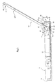
- the tray also has a lifting plate 12 movable between a low position ( Figures 2, 3 and 5) and a high position ( Figures 1, 4 and 6).
- the lifting plate 12 is suitable for cooperating with an elastic thrust member tending to return it to the high position.
- the elastic thrust member is integrated with the tray and is present in the form of a coil spring 30.
- the elastic thrust member it will be possible for the elastic thrust member to be present in other forms and to be integrated with the image forming apparatus, the important point being that its arrangement enables it to cooperate with the lifting plate of the tray in accordance with the invention, in order to return this plate to its high position.
- the lifting plate 12 is mounted pivoted on the structure of the bin 11, and more particularly on its longitudinal sides or longitudinal walls, with only one of these, side 16, being visible in Figure 2, because of the partially cut-away portion provided so that the invention can be better understood.
- the plate has a front end 31 and a rear end 32, the length of the plate here being substantially less than that of the sheets.
- the plate 12 has two mounting lugs 33 arranged on each side of the plate and themselves bearing a notch 35 each suitable for receiving a pivot 36 integral with the side 16, the pivot 36 and the notch 35, arranged on either side of the lifting plate 12, producing the pivoting of said plate on the bin 11.
- the spring 30 is arranged in the vicinity of the front end 31 of the lifting plate, in order to be compressed between said plate and the bottom 37 of the bin 11. It is held in place by means which have not been represented on the figures in order to facilitate the understanding thereof and which can easily be performed by a man skilled in the art.
- a lid 13 is also hinged on the bin 11 about an axis 14 ( Figures 2 and 3) and is intended to cover partially the bin.
- the means producing this rotation in this embodiment will be described later, with the aid of Figure 9.
- the lid has at least one limitation area 40 so that when the lifting plate is in the low position ( Figures 2, 3) and when the lid is in the open position (also Figures 2 and 3), the limitation area 40 is at a predetermined distance d from the bottom 37 corresponding to the maximum paper thickness 70 capable of being loaded into the tray ( Figure 5).
- the lifting plate 12 comes to lie on the same level as the bottom 37, here this predetermined distance is also that between the limitation area 40 and the lifting plate 12.
- the limitation area is formed by a simple ridge 41 of the lid arranged on the latter in the vicinity of the axis of rotation 14.
- the ridge 41 is arranged to have a contact surface 42 having a substantial width, so as not to damage the sheet on the top of the pile 70 (Figure 5).
- the ridge 41 may, in other embodiments, have another physical shape and be rounded, for example. Here it extends over the entire width of the lid.
- the loading tray described here has proved to be more practical during the sheet loading operations than that in the prior art given in the preamble.
- the lid 12 in normal operation the lid 12 is integral with the bin, since in this particular case it is hinged on the latter. The user does not have to detach this lid as in the prior art. It is sufficient for him to bring it into its open position ( Figures 2 and 3) which automatically positions the ridge 41 (in this particular case the surface 42) at the distance d above the bottom 37 or the lifting plate, when said plate is in the low position.
- the user thus has a visual reference in order to determine the maximum paper height. He only has to slide the pile 70 into the space left free between the lifting plate 12 and the surface 42, the lifting plate being able to be kept in its low position either because of pressure exerted by the user, or automatically, by means of the arrangement which will be described below.
- the limitation area acts as a limiter which physically prevents the user from loading more paper than the tray can contain.
- the rear end 39 of the bin 11 has at least one rear notch 44, forming a clearance
- the rear end 45 of the lid 13 has at least one rear plane limitation area 46, which is parallel to the bottom 37 of the bin (when the lid 13 is closed), the plane area 46 being offset with respect to the inner surface 47 of the lid and arranged on a support structure 48 integral with the latter.
- the support structure 48 is positioned so that in the closed position of the lid 13 it enters the notch 44, the rear plane limitation area 46 then opening on the inside of the bin 11 ( Figures 4 and 7).
- the bin includes three notches at the rear end, while the lid has three support structures 48 for rear plane limitation areas 46, a single support structure and a single notch being entirely represented on Figure 2 (only half of the second notch-structure unit being represented, because of the partially cut-away portion of Figure 2).
- the bin 11 illustrated on Figure 2 is symmetrical.
- the support structure 48 is formed by a bulge having the shape illustrated on the figures.
- a slope 54 is provided in front of the surface 46 in order to avoid damaging the comers of the sheets. This bulge is set in the mass of the material of the lid.
- FIG. 7 enables the function of the plane limitation area to be understood.
- the rear plane limitation area 46 is situated parallel to the bottom 37 of the bin.
- This surface 46 acts as an abutment surface on which the upper sheet of the pile 70 comes to bear, on the assumption that during the manipulation of the loaded tray, said tray is returned, the sheets then tending to fall on account of gravity.
- the upper sheet can not move in the direction of the inner surface 47 of the lid 13.
- the fact of disposing the surface 46 on a structure 48 so that this surface 46 is considerably offset with respect to the inner surface 47 of the lid enables, by providing the complementary notches 44 on the rear end wall 51 of the bin, an interlocking of the support structures 48 with the wall 51 to be achieved, during the closing of the lid 13. Thanks to this characteristic, the sheets, and in particular the upper sheet of the pile 70, can not slide in the gap 53 capable of existing between the inner face 47 of the lid 13 and the free upper edge 52 of the wall 51 (see the partial cut-away portion on Figure 6 in which the gap in question bears the reference 53).
- the user may manipulate the tray as soon as it is loaded without the fear of seeing certain sheets squeezed by the lid with the above-mentioned drawbacks.
- a lateral plane limitation area 46' parallel to the bottom 37 of the bin is also provided (when the lid 13 is closed).
- This lateral plane area 46' is also offset with respect to the inner surface 47 of the lid and arranged on a support structure 48' integral with the latter.
- This support structure 48' is also positioned so that in the closed position of the lid 13, it enters a lateral notch 44' acting as a clearance, the lateral plane limitation area 46' then opening on the inside of the bin 11.
- the bin has two notches of this type, each provided in a lateral wall or side 16 of the bin 11, while the lid has two support structures 48' for the lateral plane areas 46', a single lateral support structure and a single lateral notch being entirely represented on Figure 2 (the other lateral notch-lateral structure unit not being represented on the figures because of the sections and partially cut-away portions featured on them).
- the lateral support structure 48' is also formed by a bulge having the form illustrated on the figures.
- a slope 54' is also provided in front of the surface 46'.
- the functions of the lateral plane limitation area 46' and the lateral support structure 48' are the same as those given above for the rear plane limitation area-rear support structure unit. As already mentioned, the risks of jamming and of absence of feed in particular are avoided.
- the top sheet of the pile is correctly held between the lateral walls of the bin 11, when it is driven and it has left the plane rear limitation areas.
- this upper sheet is only grasped by the roller 26, but not yet by the transport rollers 25a, 25b, a displacement of the rear of this sheet towards the one or the other of the walls of the bin 11 is always possible.
- the sheet therefore arrives in the printing area with more precise positioning, guaranteeing a better quality of printed image.
- the unit of these notches 44, 44' and support structures 48, 48' form prevention means designed to prevent the passage of sheets between the lid and the bin, these notches and structures being arranged respectively on the periphery of the bin and of the lid.
- the lid 12 has at least one thrust area 55, while the lifting plate 12 has at least one bearing area 56, the thrust area and the bearing area being arranged so as to cooperate together so that, when the lid comes into its open position ( Figures 2 and 3), the said thrust area 55 pushes the lifting plate towards its low position ( Figure 3) in opposition to the elastic thrust member (the spring 30).
- the area is arranged at the end of an arm 57 integral with the lid 13, while the bearing area 56 is arranged on a lug integral with the lifting plate.
- the arm 57 bearing the thrust area is provided at the front end of the lid 13, on the side thereof (the lid 13 has two of these arms, as it is symmetrical with respect to the cut-away plane of Figure 2).
- the lug bearing the bearing area of the lifting plate is arranged on the side of the latter, two of these lugs being in reality provided on either side of the lifting plate, in the vicinity of the front end thereof.
- the arm 57 is arranged on the lid 13 with respect to the axis 14 so that during the opening movement, the thrust area 55 provided at the end of the arm 57 comes into contact with the bearing area 56 and then pushes the lifting plate 12 towards the bottom 37 of the bin, as illustrated in particular in Figures 2 and 3.
- the bin 11 has two tabs 60 for holding the front comers 61 of the sheets 70. These tabs open onto the inside of the bin 11 and have a holding surface 62 arranged with respect to the lifting plate 12 at least at the same distance as that between the limitation area 40 and the bottom 37, here the lifting plate when it is in its low position, the said lid being open ( Figures 3 and 5).
- the distance d existing between the surface 42 and the upper surface of the lifting plate 12 is less than the distance d' existing between the surface 62 and the lifting plate 12, when it is in its low position, the lid 13 being open.
- the function of the holding tabs 60, and more precisely their holding surface 62, is as in the prior art, to hold the paper in the tray ( Figures 6 and 6a), in particular during the loading operations, at the feeding end of the tray.
- the surface 62 is provided at a distance d' greater than the distance d, there is no risk during loading of seeing certain upper sheets of the pile 70 coming to abut against the tabs 60 and the corners being damaged as a result.
- Figure 9 shows that a vertically oriented guide surface parallel to the longitudinal axis of the tray is arranged directly below the holding surface 62 of each tab 60.
- the vertical guide surface bears the reference 65. Two of these surfaces are obviously provided, directly below each of the tabs 60, the guide surfaces 65 being spaced by a distance substantially greater than the width of the sheets. They are preceded by an obliquely oriented guide surface 64 having two functions:
- the pivoting means are adapted to be separated automatically in the event of an impact of predetermined force exerted on the lid, the latter thereby being disconnected from the housing.
- the means for pivoting the lid about the said axis includes a pivot 90 arranged at each side of the lid 13 on a lateral elastic lug 91, the pivot 90 having a disengagement slope 92 oriented obliquely with respect to the axis of the pivot (cf. Figure 10).
- a cylindrical housing 93 having dimensions complementary to the pivot 90 is provided in the wall 16, on the inner side thereof, the cylindrical housing having the axis 14 as its axis.
- slopes 92 arranged on the pivots on either side of the lid are overall oriented towards one another and are at their closest in the vicinity of the lower end of the elastic lugs 91.
- slopes 92 have a double function:
- a snapping-in slope 95 provided on the inner side of the wall 16 is provided directly above the cylindrical housing 93, in order to facilitate the snapping-in of the pivot 90 in the housing 93 by a guiding of this pivot and a regular flexion of the lug 91, and also the accidental dismantling of the pivoting means further to a shock on the lid.
- the predetermined distance relative to the limitation area will simply be that between this area and the bottom of the bin if the lifting plate does not extend as far as the rear end of the bin.
Landscapes
- Engineering & Computer Science (AREA)
- Mechanical Engineering (AREA)
- Pile Receivers (AREA)
- Sheets, Magazines, And Separation Thereof (AREA)
Applications Claiming Priority (2)
| Application Number | Priority Date | Filing Date | Title |
|---|---|---|---|
| FR9412994 | 1994-10-28 | ||
| FR9412994A FR2726222A1 (fr) | 1994-10-28 | 1994-10-28 | Cassette de chargement de feuilles comportant un receptacle et un couvercle ayant des moyens de prevention empechant le passage de feuilles entre le couvercle et le receptacle |
Publications (2)
| Publication Number | Publication Date |
|---|---|
| EP0709321A1 true EP0709321A1 (fr) | 1996-05-01 |
| EP0709321B1 EP0709321B1 (fr) | 2002-02-06 |
Family
ID=9468360
Family Applications (1)
| Application Number | Title | Priority Date | Filing Date |
|---|---|---|---|
| EP95402386A Expired - Lifetime EP0709321B1 (fr) | 1994-10-28 | 1995-10-25 | Cassette de chargement de feuilles comportant un réceptacle et un couvercle ayant des moyens de prévention empêchant le passage de feuilles entre le couvercle et le réceptacle |
Country Status (4)
| Country | Link |
|---|---|
| US (1) | US5775687A (fr) |
| EP (1) | EP0709321B1 (fr) |
| DE (1) | DE69525304T2 (fr) |
| FR (1) | FR2726222A1 (fr) |
Families Citing this family (7)
| Publication number | Priority date | Publication date | Assignee | Title |
|---|---|---|---|---|
| JP2000128367A (ja) * | 1998-10-21 | 2000-05-09 | Matsushita Graphic Communication Systems Inc | 給紙トレーおよびこれを備えた画像記録装置 |
| US7641190B2 (en) * | 2002-07-12 | 2010-01-05 | Oki Data Corporation | Medium tray and image recording apparatus using the same |
| JP4046649B2 (ja) * | 2003-06-10 | 2008-02-13 | 三洋電機株式会社 | 給紙トレイ |
| US7131644B2 (en) * | 2004-04-06 | 2006-11-07 | Lexmark International, Inc. | Imaging apparatus having an automatic sheet feeder |
| US7484727B2 (en) * | 2004-04-28 | 2009-02-03 | Samsung Electronics Co., Ltd. | Media cassette with removable spacer used in a printing apparatus |
| JP2008280162A (ja) * | 2007-05-14 | 2008-11-20 | Seiko Epson Corp | 給紙装置 |
| US8202015B2 (en) * | 2007-06-27 | 2012-06-19 | Hewlett-Packard Development Company, L.P. | Media tray assembly and a printer having the same |
Citations (2)
| Publication number | Priority date | Publication date | Assignee | Title |
|---|---|---|---|---|
| US4032137A (en) * | 1974-10-22 | 1977-06-28 | Canon Kabushiki Kaisha | Feed cassette device |
| EP0575996A1 (fr) * | 1992-06-24 | 1993-12-29 | Canon Kabushiki Kaisha | Appareil d'alimentation en feuilles |
Family Cites Families (3)
| Publication number | Priority date | Publication date | Assignee | Title |
|---|---|---|---|---|
| US4406448A (en) * | 1981-07-24 | 1983-09-27 | Pitney Bowes Inc. | Paper cassette |
| DE3906983C2 (de) * | 1989-03-04 | 1995-12-21 | Kodak Ag | Vorratskassette für einen Blattstapel |
| EP0499283B1 (fr) * | 1991-02-15 | 1994-12-07 | Mita Industrial Co., Ltd. | Cassette pour alimenter des matériaux en forme de feuille |
-
1994
- 1994-10-28 FR FR9412994A patent/FR2726222A1/fr not_active Withdrawn
-
1995
- 1995-10-25 US US08/547,816 patent/US5775687A/en not_active Expired - Lifetime
- 1995-10-25 DE DE69525304T patent/DE69525304T2/de not_active Expired - Lifetime
- 1995-10-25 EP EP95402386A patent/EP0709321B1/fr not_active Expired - Lifetime
Patent Citations (2)
| Publication number | Priority date | Publication date | Assignee | Title |
|---|---|---|---|---|
| US4032137A (en) * | 1974-10-22 | 1977-06-28 | Canon Kabushiki Kaisha | Feed cassette device |
| EP0575996A1 (fr) * | 1992-06-24 | 1993-12-29 | Canon Kabushiki Kaisha | Appareil d'alimentation en feuilles |
Also Published As
| Publication number | Publication date |
|---|---|
| DE69525304D1 (de) | 2002-03-21 |
| DE69525304T2 (de) | 2002-08-14 |
| EP0709321B1 (fr) | 2002-02-06 |
| US5775687A (en) | 1998-07-07 |
| FR2726222A1 (fr) | 1996-05-03 |
Similar Documents
| Publication | Publication Date | Title |
|---|---|---|
| US4219192A (en) | Sheet loading and storing assembly | |
| US5957447A (en) | Corner separator paper feed method and cassette which prevents paper jams during manual feeding | |
| US5752696A (en) | Tray for loading sheets in a sheet-processing apparatus having an elastic force maintaining a lid in an open position | |
| JPH07196173A (ja) | シート積載装置及び画像形成装置 | |
| EP0709321B1 (fr) | Cassette de chargement de feuilles comportant un réceptacle et un couvercle ayant des moyens de prévention empêchant le passage de feuilles entre le couvercle et le réceptacle | |
| JPS6150860B2 (fr) | ||
| US5232214A (en) | Paper supplying apparatus and method using a detachable cassette | |
| GB2053159A (en) | Copy paper feeding cassette | |
| EP0367200A2 (fr) | Dispositif d'alimentation de feuilles | |
| US5328167A (en) | Sheet feed apparatus | |
| US8038359B2 (en) | Printing medium supply device and image forming apparatus having the same | |
| US5338021A (en) | Paper feeding mechanism | |
| EP0700851A1 (fr) | Dispositif d'alimentation de feuille destiné à être monté sur un appareil de formation d'image | |
| JPH06271089A (ja) | 標準サイズトレーから特大紙を給紙するカートリッジ | |
| EP4700489A1 (fr) | Appareil de formation d'images | |
| JPH0761611A (ja) | 給紙装置 | |
| JPH0124032Y2 (fr) | ||
| JPH023184B2 (fr) | ||
| JP3449149B2 (ja) | 給紙装置 | |
| JPH0355965Y2 (fr) | ||
| JPH09110182A (ja) | 自動給紙トレイ | |
| JPS59230957A (ja) | シ−ト積載装置 | |
| JP3558196B2 (ja) | 給紙装置 | |
| EP0367202B1 (fr) | Dispositif d'alimentation de feuilles | |
| JP4189097B2 (ja) | 給紙カセット |
Legal Events
| Date | Code | Title | Description |
|---|---|---|---|
| PUAI | Public reference made under article 153(3) epc to a published international application that has entered the european phase |
Free format text: ORIGINAL CODE: 0009012 |
|
| AK | Designated contracting states |
Kind code of ref document: A1 Designated state(s): DE ES FR GB IT |
|
| 17P | Request for examination filed |
Effective date: 19960918 |
|
| 17Q | First examination report despatched |
Effective date: 19970425 |
|
| GRAG | Despatch of communication of intention to grant |
Free format text: ORIGINAL CODE: EPIDOS AGRA |
|
| GRAG | Despatch of communication of intention to grant |
Free format text: ORIGINAL CODE: EPIDOS AGRA |
|
| GRAH | Despatch of communication of intention to grant a patent |
Free format text: ORIGINAL CODE: EPIDOS IGRA |
|
| GRAH | Despatch of communication of intention to grant a patent |
Free format text: ORIGINAL CODE: EPIDOS IGRA |
|
| GRAA | (expected) grant |
Free format text: ORIGINAL CODE: 0009210 |
|
| REG | Reference to a national code |
Ref country code: GB Ref legal event code: IF02 |
|
| AK | Designated contracting states |
Kind code of ref document: B1 Designated state(s): DE ES FR GB IT |
|
| PG25 | Lapsed in a contracting state [announced via postgrant information from national office to epo] |
Ref country code: IT Free format text: LAPSE BECAUSE OF FAILURE TO SUBMIT A TRANSLATION OF THE DESCRIPTION OR TO PAY THE FEE WITHIN THE PRE;WARNING: LAPSES OF ITALIAN PATENTS WITH EFFECTIVE DATE BEFORE 2007 MAY HAVE OCCURRED AT ANY TIME BEFORE 2007. THE CORRECT EFFECTIVE DATE MAY BE DIFFERENT FROM THE ONE RECORDED.SCRIBED TIME-LIMIT Effective date: 20020206 |
|
| REF | Corresponds to: |
Ref document number: 69525304 Country of ref document: DE Date of ref document: 20020321 |
|
| PG25 | Lapsed in a contracting state [announced via postgrant information from national office to epo] |
Ref country code: ES Free format text: LAPSE BECAUSE OF FAILURE TO SUBMIT A TRANSLATION OF THE DESCRIPTION OR TO PAY THE FEE WITHIN THE PRESCRIBED TIME-LIMIT Effective date: 20020829 |
|
| PLBE | No opposition filed within time limit |
Free format text: ORIGINAL CODE: 0009261 |
|
| STAA | Information on the status of an ep patent application or granted ep patent |
Free format text: STATUS: NO OPPOSITION FILED WITHIN TIME LIMIT |
|
| 26N | No opposition filed |
Effective date: 20021107 |
|
| PGFP | Annual fee paid to national office [announced via postgrant information from national office to epo] |
Ref country code: FR Payment date: 20121127 Year of fee payment: 18 Ref country code: DE Payment date: 20121031 Year of fee payment: 18 |
|
| PGFP | Annual fee paid to national office [announced via postgrant information from national office to epo] |
Ref country code: GB Payment date: 20121016 Year of fee payment: 18 |
|
| GBPC | Gb: european patent ceased through non-payment of renewal fee |
Effective date: 20131025 |
|
| PG25 | Lapsed in a contracting state [announced via postgrant information from national office to epo] |
Ref country code: GB Free format text: LAPSE BECAUSE OF NON-PAYMENT OF DUE FEES Effective date: 20131025 |
|
| REG | Reference to a national code |
Ref country code: DE Ref legal event code: R119 Ref document number: 69525304 Country of ref document: DE Effective date: 20140501 |
|
| REG | Reference to a national code |
Ref country code: FR Ref legal event code: ST Effective date: 20140630 |
|
| PG25 | Lapsed in a contracting state [announced via postgrant information from national office to epo] |
Ref country code: DE Free format text: LAPSE BECAUSE OF NON-PAYMENT OF DUE FEES Effective date: 20140501 Ref country code: FR Free format text: LAPSE BECAUSE OF NON-PAYMENT OF DUE FEES Effective date: 20131031 |