EP0709513B1 - Machines à laver et/ou à sécher incorporant un éclairage - Google Patents
Machines à laver et/ou à sécher incorporant un éclairage Download PDFInfo
- Publication number
- EP0709513B1 EP0709513B1 EP95116269A EP95116269A EP0709513B1 EP 0709513 B1 EP0709513 B1 EP 0709513B1 EP 95116269 A EP95116269 A EP 95116269A EP 95116269 A EP95116269 A EP 95116269A EP 0709513 B1 EP0709513 B1 EP 0709513B1
- Authority
- EP
- European Patent Office
- Prior art keywords
- washing
- light
- machine
- drying machine
- dial
- Prior art date
- Legal status (The legal status is an assumption and is not a legal conclusion. Google has not performed a legal analysis and makes no representation as to the accuracy of the status listed.)
- Expired - Lifetime
Links
Images
Classifications
-
- D—TEXTILES; PAPER
- D06—TREATMENT OF TEXTILES OR THE LIKE; LAUNDERING; FLEXIBLE MATERIALS NOT OTHERWISE PROVIDED FOR
- D06F—LAUNDERING, DRYING, IRONING, PRESSING OR FOLDING TEXTILE ARTICLES
- D06F34/00—Details of control systems for washing machines, washer-dryers or laundry dryers
- D06F34/28—Arrangements for programme selection, e.g. control panels therefor; Arrangements for indicating programme parameters, e.g. the selected programme or its progress
- D06F34/32—Arrangements for programme selection, e.g. control panels therefor; Arrangements for indicating programme parameters, e.g. the selected programme or its progress characterised by graphical features, e.g. touchscreens
-
- D—TEXTILES; PAPER
- D06—TREATMENT OF TEXTILES OR THE LIKE; LAUNDERING; FLEXIBLE MATERIALS NOT OTHERWISE PROVIDED FOR
- D06F—LAUNDERING, DRYING, IRONING, PRESSING OR FOLDING TEXTILE ARTICLES
- D06F2103/00—Parameters monitored or detected for the control of domestic laundry washing machines, washer-dryers or laundry dryers
- D06F2103/40—Opening or locking status of doors
-
- D—TEXTILES; PAPER
- D06—TREATMENT OF TEXTILES OR THE LIKE; LAUNDERING; FLEXIBLE MATERIALS NOT OTHERWISE PROVIDED FOR
- D06F—LAUNDERING, DRYING, IRONING, PRESSING OR FOLDING TEXTILE ARTICLES
- D06F2105/00—Systems or parameters controlled or affected by the control systems of washing machines, washer-dryers or laundry dryers
- D06F2105/44—Opening, closing or locking of doors
-
- H—ELECTRICITY
- H01—ELECTRIC ELEMENTS
- H01H—ELECTRIC SWITCHES; RELAYS; SELECTORS; EMERGENCY PROTECTIVE DEVICES
- H01H3/00—Mechanisms for operating contacts
- H01H3/02—Operating parts, i.e. for operating driving mechanism by a mechanical force external to the switch
- H01H3/08—Turn knobs
- H01H2003/085—Retractable turn knobs, e.g. flush mounted
Definitions
- the present invention relates to a washing and/or drying machine, as described in the preamble of the enclosed first claim.
- the machines of the type mentioned are equipped with a control panel in the upper section of the cabinet, where the various controls are located, such as the programmer of the washing cycles, the selectors for the temperature, basket rotation speed, drying time, etc., the eventual buttons for enabling particular functions (e.g. half load, spinning suppression, etc.) and a main power switch (ON/OFF).
- the various controls such as the programmer of the washing cycles, the selectors for the temperature, basket rotation speed, drying time, etc., the eventual buttons for enabling particular functions (e.g. half load, spinning suppression, etc.) and a main power switch (ON/OFF).
- the reading and/or selecting of functional commands of the machine, and in particular selecting the desired washing program can result in being difficult; in light of this, therefore, it would be advantageous to supply the washing machine with at least one appropriate light, for illuminating the control panel.
- the same considerations made with regards illuminating the control panel are also valid for illuminating the interior of the basket of a laundry washing and/or drying machine.
- the operative sequence of use of the machine in substance requires that the loading of the laundry to washed and/or dried in the basket of the machine, the addition of the washing agents in the relative dispenser and the selection of the desired washing program, by way of selection on the programmer of the machine, have to take place before turning on the machine, which takes place by way of the main power switch (ON/OFF).
- the present invention is based on the acknowledgement of the aforementioned facts and its purpose is that of indicating a washing and/or drying machine equipped with a light, the switching on of which being independent from the main power switch of the machine.
- Another purpose of the invention is that of indicating a machine in which the system for switching on such light takes advantage of a pre-existing command means, dedicated to controlling other functions; in light of this, therefore, the purpose of the invention is that of avoiding that the aesthetic appearance of the control panel be modified and/or burdened by the addition of an appropriate command means for switching on the light.
- a further purpose of the invention is that of indicating a command method on the basis of which the switching on of a light is allowed in a manner which does not implicate any additional operation for the user respect those carried out on machines of the known type.
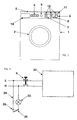
- FIG 1 a washing and/or drying machine is schematically represented realised according to the details of the present invention, in particular a front loading laundry washing machine.
- 1 indicates the cabinet of the machine as a whole
- 2 indicates its front loading door, which gives access to the basket for the laundry
- 3 indicates its control panel.
- the control panel 3 is arranged in the upper part of the cabinet 1 and has a series of commands, from among which:
- a transparent element of the control panel 3 is indicated, behind which three indicator disks 12 are arranged, each of which being coupled to one of the dials 5, 6 and 7; such disks 12 have appropriate printed script that indicate the various options which can be selected: thus the user can read through the transparent part 11 such printed scripts and rotate the relative dial for selecting the desired washing cycle, the temperature and the spinning speed.
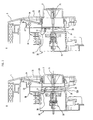
- dial 5 of the washing cycles programmer is of the type apt at assuming the two following axial functional positions (respectively visible in parts A and B of figure 2):
- the change from one position to the other is obtained by simply pressing the frontal surface of the dial 5, that has an appropriate kinematic blocking/release system.
- the other dials 6 and 7 are, on the other hand, in the case illustrated, of the traditional type and therefore protruding (but could obviously be of the same type as the dial 5).
- Figure 2 illustrates, by way of two schematic sectioned views, the part of the control panel 3 where the programmer of the machine is housed, with the relative dial 5; according to the invention, in such part of the control panel, a light is provided, able to facilitate the selection of the program in the aforementioned cases of poor light, supplied independently from the position of the on/off switch 9 of the machine.
- the actual timer or programmer is indicated as a whole with 20, that in the illustrated case is of the electro-mechanical type, in itself known, thus not requiring a detailed description;
- 21 indicates a shaft, which allows, by way of the dial 5, the manual rotation of the internal cam group of the programmer 20 (or the contact setting of an electronic board, in the case of an electronic timer), and thus the selection of the desired washing program;
- 22 indicates a bistable kinematic system, which allows the shaft 21 to take on two different axial positions, clearly visible in comparing parts A and B of figure 2; such kinematic system 22 therefore allows the dial 5 to take on the two functional positions as described above.
- Such kinematic system 22 comprises a mobile element having inclined planes and a spiral spring, is of the type in itself known (generally with the name push-push) and widely used on existing washing machines, for allowing the extraction from the control panel 3 of the command dial 5.
- one of the mentioned disks 12 is indicated, which is integral to the shaft 21 and has a printed script indicating the various programs that can be selected, which the user can consult through the transparent element 11.
- a light for instance a neon, fixed in the known way to the interior of the control panel 3, behind a shield 24; such shield 24 is realised in a transparent material, or able to refract and/or diffuse the light coming from the light 23, so as to illuminate the printed surface of the disk 12A.
- a first contact element is indicated, fixed, electrically connected to the phase (L) of the electrical mains; 26 indicates a second contact element, mobile against the push of a spiral spring 27, which is electrically connected, through a conductor 28, to a pole of the light 23; the other pole of the light, not represented, can be connected in an appropriate manner, in a known way, directly to the neutral (N) of the electrical mains.
- a projection 21A of the shaft 21 maintains the switch, constituted by the contacts 25 and 26 open, in contrast to the action of the spring 27; when on the contrary the dial 5 is brought to the working position (fig. 2, part B), the movement of the shaft 21, and therefore of the projection 21A, allows for the closure of the switch 25-26, as a result of the action of the spring 27, with the consequent switching on of the light 23.
- the switching on of the light 23 is made possible independently from the functional state of the main switch 9 of the machine (i.e. even when such machine is in the OFF position).
- FIG 3 with this purpose the simplified electric diagram of the machine according to the invention is illustrated; with L and N the phase and neutral of the electrical mains are respectively indicated, while 30 globally represents the electrical control and actuation circuit of the machine, enclosing the programmer 20 and all the various electrical devices of the machine (motor, pumps, solenoid heating resistance, etc.).
- connection of the light 23 is such to allow its switching on even in conditions of the main power switch 9 being open, i.e. with no power supply of the circuit 30.
- the above described system of switching on the light 23 could be applied to a dial, similar to that indicated with 5, provided for the opening of the laundry loading door; in such case, therefore, for the machines which provide for opening the door from the control panel, with the door opening command a simultaneous switching on of a light for the inside the basket could be obtained.
- a plurality of lights, or light emitters, for illuminating and/or emphasising the various command means of the machine could be provided, or the system for switching on the light or lights could be realised on all the dials (5-7) present on the machine.
Landscapes
- Engineering & Computer Science (AREA)
- Textile Engineering (AREA)
- Control Of Washing Machine And Dryer (AREA)
- Washing And Drying Of Tableware (AREA)
- Detail Structures Of Washing Machines And Dryers (AREA)
Claims (15)
- Machine à laver et/ou à sécher, comme par exemple un lave-linge ou un lave-vaisselle, comprenantcaractérisée en ce que la lampe (23) est connectée au réseau électrique (L,N) en amont de l'interrupteur principal (9) de sorte qu'elle peut être alimentée électriquement d'une manière indépendante de l'état dudit interrupteur principal (9), et en ce que l'alimentation électrique de la lampe (23) est branchée à l'aide de moyens de commutation (25-27) activés par l'intermédiaire d'au moins un premier (5) desdits moyens de commande (5-8), ledit premier moyen de commande (5) étant prévu principalement pour la sélection d'autres modes d'utilisation de la machine.un circuit électrique de commande et d'actionnement (30) comprenant une pluralité de dispositifs à produits pour exécuter les fonctions pour lesquelles la machine est destinée (lavage et/ou séchage du linge ou de la vaisselle), et un ou plusieurs moyens de commande (5-8) pour la sélection manuelle des modes d'utilisation de la machine,un interrupteur principal (9) pour brancher/débrancher l'alimentation en énergie appliquée audit circuit électrique de commande et d'actionnement (30),une lampe (23),
- Machine à laver et/ou à sécher selon la revendication 1, caractérisée en ce qu'il est prévu des moyens (22,25-27) qui, lors de l'activation dudit premier moyen de commande (5), réalisent automatiquement le branchement de la lampe (23).
- Machine à laver et/ou à sécher selon la revendication 1, caractérisée en ce que lesdits premiers moyens de commande (5,20) sont un programmateur de cycles de lavage (5).
- Machine à laver et/ou à sécher selon la revendication 1, caractérisée en ce que ledit premier moyen de commande est du type comprenant un cadran (5) apte à prendre deux positions de fonctionnement axiales différentes (figure 2), et notamment :une première position de repos, dans laquelle le cadran (5) est logé au moins partiellement dans un logement approprié présent sur le panneau de commande (3),une seconde position de travail, dans laquelle le cadran (5) ressort dudit logement, de sorte que l'utilisateur peut faire tourner le cadran.
- Machine à laver et/ou à sécher selon la revendication 1, caractérisée en ce que la lampe (23) est destinée à éclairer les différentes options disponibles (cycle de lavage, température, vitesse de rotation, etc.) à l'aide d'un ou de plusieurs moyens de commande (5-8) présents sur le panneau de commande (3) de la machine.
- Machine à laver et/ou à sécher selon la revendication 5, caractérisée en ce que la lampe (23) est fixée au panneau de commande, en particulier sur le côté intérieur, en arrière d'un écran (24) réalisé en un matériau transparent et/ou apte à réfracter et/ou à diffuser la lumière délivrée par la lampe (23).
- Machine à laver et/ou à sécher selon la revendication 1, caractérisée en ce que lesdits moyens de commutation (25-27) comprennent un premier contact fixe (25) et un second contact (26), qui est mobile avec ledit cadran (5), le second contact (26) étant notamment solidaire d'un arbre réalisé d'un seul tenant avec un arbre (21) raccordé au cadran (5).
- Machine à laver et/ou à sécher selon les revendications 4 et 7, caractérisée en ce que, dans la position de repos (figure 2, partie A), le cadran (5) et/ou l'arbre rotatif (21) maintiennent le second contact (26) écarté du premier contact (25) alors que, lorsque le cadran (5) est placé dans la position de travail (figure 2, partie B), le déplacement du cadran (5) et/ou de l'arbre rotatif (21) détermine la fermeture du second contact (26) sur le premier contact (25), ce qui permet l'alimentation en énergie de la lampe (23).
- Machine à laver et/ou à sécher selon au moins l'une des revendications précédentes, caractérisée en ce que le premier contact (25) est connecté électriquement à la phase (L) du réseau électrique et que le second contact (26) est connecté à un pôle de la lampe (23), l'autre pôle de la lampe (23) étant connecté notamment au neutre (N) du réseau électrique.
- Machine à laver et/ou à sécher selon la revendication 1, caractérisée en ce que la lampe (23) est destinée à éclairer l'intérieur du panier d'un lave-linge et/ou d'un lave-vaisselle.
- Machine à laver et/ou à sécher selon la revendication précédente, caractérisée en ce que lesdits premiers moyens de commande sont un dispositif servant à ouvrir la porte (2) de chargement du linge, la commande d'ouverture de la porte (2) étant à même de déterminer également l'allumage simultané de la lampe (23) de l'intérieur du panier.
- Machine à laver et/ou à sécher selon au moins l'une des revendications précédentes, caractérisée en qu'il est prévu une pluralité de lampes (23) ou de sources de lumière pour éclairer et/ou mettre en relief un ou plusieurs moyens de commande (5-8) de la machine.
- Machine à laver et/ou à sécher selon au moins l'une des revendications précédentes, caractérisée en ce que chacun des moyens de commande (5-8) est à même de commander l'allumage d'une ou de plusieurs lampes (23).
- Machine à laver et/ou à sécher selon au moins la revendication 1, caractérisée en ce que la lampe (23) est destinée à éclairer un tiroir servant à loger les agents de lavage (10).
- Procédé pour commander une lampe dans une machine à laver et/ou à sécher, caractérisé en ce qu'il permet l'intégration substantielle de moyens de commande de la lampe (23) dans un dispositif de commande (5) prévu pour sélectionner au moins une utilisation fonctionnelle de la machine, d'une manière telle que lors de la sélection de ladite utilisation fonctionnelle de la machine (par exemple sélection du cycle de lavage), au moyen du dispositif de commande (5), l'utilisateur obtient également, d'une manière automatique, l'allumage de la lampe (23) au moyen d'un simple actionnement du cadran (5) du dispositif de commande n'étant en soi pas tenu d'exécuter des opérations additionnelles en dehors de celles normalement prévues.
Applications Claiming Priority (2)
| Application Number | Priority Date | Filing Date | Title |
|---|---|---|---|
| IT94TO000858A IT1268140B1 (it) | 1994-10-26 | 1994-10-26 | Macchina di lavaggio e/o asciugatura, con lampada di illuminazione. |
| ITTO940858 | 1994-10-26 |
Publications (2)
| Publication Number | Publication Date |
|---|---|
| EP0709513A1 EP0709513A1 (fr) | 1996-05-01 |
| EP0709513B1 true EP0709513B1 (fr) | 2000-03-08 |
Family
ID=11412856
Family Applications (1)
| Application Number | Title | Priority Date | Filing Date |
|---|---|---|---|
| EP95116269A Expired - Lifetime EP0709513B1 (fr) | 1994-10-26 | 1995-10-16 | Machines à laver et/ou à sécher incorporant un éclairage |
Country Status (4)
| Country | Link |
|---|---|
| EP (1) | EP0709513B1 (fr) |
| DE (1) | DE69515414T2 (fr) |
| ES (1) | ES2144557T3 (fr) |
| IT (1) | IT1268140B1 (fr) |
Families Citing this family (6)
| Publication number | Priority date | Publication date | Assignee | Title |
|---|---|---|---|---|
| US6341202B1 (en) | 1999-06-22 | 2002-01-22 | Asahi Kogaku Kogyo Kabushiki Kaisha | Operation dial with an illuminator for a camera |
| KR100720568B1 (ko) * | 2000-09-08 | 2007-05-22 | 엘지전자 주식회사 | 세탁기의 컨트롤러 어셈블리 |
| DE10214920A1 (de) | 2002-04-04 | 2003-10-16 | Bsh Bosch Siemens Hausgeraete | Bedieneinheit und Gargerät |
| DE10235694A1 (de) * | 2002-08-03 | 2004-02-19 | Electrolux Home Products Corporation N.V. | Versenkbare Drehknebeleinheit |
| KR101125389B1 (ko) * | 2004-06-30 | 2012-03-27 | 엘지전자 주식회사 | 드럼 세탁기의 다이얼 놉 구조 및 그 제조 방법 |
| DE102005024934B4 (de) * | 2005-05-31 | 2014-03-27 | BSH Bosch und Siemens Hausgeräte GmbH | Bedienblendenanordnung für ein Haushaltgerät |
Family Cites Families (3)
| Publication number | Priority date | Publication date | Assignee | Title |
|---|---|---|---|---|
| US2737573A (en) * | 1953-10-28 | 1956-03-06 | Gen Electric | Lighting means for automatic clothes washers |
| FR1363826A (fr) * | 1962-07-23 | 1964-06-12 | Junkers & Co | Machine à laver commandée par des cartes de programmation |
| JPH05261193A (ja) * | 1992-03-19 | 1993-10-12 | Toshiba Corp | 二槽式洗濯機 |
-
1994
- 1994-10-26 IT IT94TO000858A patent/IT1268140B1/it active IP Right Grant
-
1995
- 1995-10-16 EP EP95116269A patent/EP0709513B1/fr not_active Expired - Lifetime
- 1995-10-16 DE DE69515414T patent/DE69515414T2/de not_active Expired - Fee Related
- 1995-10-16 ES ES95116269T patent/ES2144557T3/es not_active Expired - Lifetime
Also Published As
| Publication number | Publication date |
|---|---|
| EP0709513A1 (fr) | 1996-05-01 |
| ITTO940858A1 (it) | 1996-04-26 |
| IT1268140B1 (it) | 1997-02-20 |
| ITTO940858A0 (it) | 1994-10-26 |
| ES2144557T3 (es) | 2000-06-16 |
| DE69515414T2 (de) | 2000-10-26 |
| DE69515414D1 (de) | 2000-04-13 |
Similar Documents
| Publication | Publication Date | Title |
|---|---|---|
| EP2218064B1 (fr) | Ensemble module d'affichage à diode électroluminescente et dispositif de lavage comprenant celui-ci | |
| EP3225731B1 (fr) | Lave-linge | |
| CA2071330C (fr) | Systeme de controle de temoin lumineux d'appareil et methode d'utilisation | |
| EP1847643B1 (fr) | Système de communication d'informations dans un appareil | |
| KR100720568B1 (ko) | 세탁기의 컨트롤러 어셈블리 | |
| KR102725969B1 (ko) | 의류처리장치 | |
| CA2527758C (fr) | Appareil electromenager avec membrane de recouvrement sur le tableau de commande | |
| US5038587A (en) | Control system | |
| EP0709513A1 (fr) | Machines à laver et/ou à sécher incorporant un éclairage | |
| US3861413A (en) | Indicating device for a dishwasher | |
| US4355217A (en) | Switch inhibitor for timers | |
| EP3168356B1 (fr) | Appareil ménager pourvu d'un élément d'interface utilisateur de rotation | |
| KR102711598B1 (ko) | 의류처리장치 | |
| US4249090A (en) | Automatic resetting power saver switch for dishwasher | |
| US5001910A (en) | Control system | |
| KR102714484B1 (ko) | 의류처리장치 | |
| EP0401734A2 (fr) | Dispositif pour positionner le tambour d'une machine à laver | |
| JP4096673B2 (ja) | 電気洗濯機 | |
| US4748296A (en) | Push-to-start control switch | |
| EP0848928B1 (fr) | Porte avec un dispositif pour la sélection des programmes de lavage dans une machine à laver | |
| EP0505684B1 (fr) | Dispositif de programmation pour une machine à laver | |
| KR100730938B1 (ko) | 드럼 세탁기용 다이얼 버튼 | |
| CA2027950C (fr) | Dispositif de commande | |
| US2984755A (en) | Control mechanism | |
| KR0131551Y1 (ko) | 세탁기 |
Legal Events
| Date | Code | Title | Description |
|---|---|---|---|
| PUAI | Public reference made under article 153(3) epc to a published international application that has entered the european phase |
Free format text: ORIGINAL CODE: 0009012 |
|
| AK | Designated contracting states |
Kind code of ref document: A1 Designated state(s): DE ES FR GB |
|
| 17P | Request for examination filed |
Effective date: 19961104 |
|
| GRAG | Despatch of communication of intention to grant |
Free format text: ORIGINAL CODE: EPIDOS AGRA |
|
| 17Q | First examination report despatched |
Effective date: 19990324 |
|
| GRAG | Despatch of communication of intention to grant |
Free format text: ORIGINAL CODE: EPIDOS AGRA |
|
| GRAH | Despatch of communication of intention to grant a patent |
Free format text: ORIGINAL CODE: EPIDOS IGRA |
|
| GRAH | Despatch of communication of intention to grant a patent |
Free format text: ORIGINAL CODE: EPIDOS IGRA |
|
| GRAA | (expected) grant |
Free format text: ORIGINAL CODE: 0009210 |
|
| AK | Designated contracting states |
Kind code of ref document: B1 Designated state(s): DE ES FR GB |
|
| REF | Corresponds to: |
Ref document number: 69515414 Country of ref document: DE Date of ref document: 20000413 |
|
| REG | Reference to a national code |
Ref country code: ES Ref legal event code: FG2A Ref document number: 2144557 Country of ref document: ES Kind code of ref document: T3 |
|
| ET | Fr: translation filed | ||
| PLBE | No opposition filed within time limit |
Free format text: ORIGINAL CODE: 0009261 |
|
| STAA | Information on the status of an ep patent application or granted ep patent |
Free format text: STATUS: NO OPPOSITION FILED WITHIN TIME LIMIT |
|
| 26N | No opposition filed | ||
| REG | Reference to a national code |
Ref country code: GB Ref legal event code: IF02 |
|
| PGFP | Annual fee paid to national office [announced via postgrant information from national office to epo] |
Ref country code: GB Payment date: 20060925 Year of fee payment: 12 |
|
| PGFP | Annual fee paid to national office [announced via postgrant information from national office to epo] |
Ref country code: ES Payment date: 20061006 Year of fee payment: 12 |
|
| PGFP | Annual fee paid to national office [announced via postgrant information from national office to epo] |
Ref country code: DE Payment date: 20061107 Year of fee payment: 12 |
|
| GBPC | Gb: european patent ceased through non-payment of renewal fee |
Effective date: 20071016 |
|
| PG25 | Lapsed in a contracting state [announced via postgrant information from national office to epo] |
Ref country code: DE Free format text: LAPSE BECAUSE OF NON-PAYMENT OF DUE FEES Effective date: 20080501 |
|
| REG | Reference to a national code |
Ref country code: FR Ref legal event code: ST Effective date: 20080630 |
|
| PGFP | Annual fee paid to national office [announced via postgrant information from national office to epo] |
Ref country code: FR Payment date: 20061013 Year of fee payment: 12 |
|
| PG25 | Lapsed in a contracting state [announced via postgrant information from national office to epo] |
Ref country code: GB Free format text: LAPSE BECAUSE OF NON-PAYMENT OF DUE FEES Effective date: 20071016 |
|
| REG | Reference to a national code |
Ref country code: ES Ref legal event code: FD2A Effective date: 20071017 |
|
| PG25 | Lapsed in a contracting state [announced via postgrant information from national office to epo] |
Ref country code: FR Free format text: LAPSE BECAUSE OF NON-PAYMENT OF DUE FEES Effective date: 20071031 Ref country code: ES Free format text: LAPSE BECAUSE OF NON-PAYMENT OF DUE FEES Effective date: 20071017 |