EP0709515A1 - Dispositif d'entraînement pour sèche-linge domestique - Google Patents
Dispositif d'entraînement pour sèche-linge domestique Download PDFInfo
- Publication number
- EP0709515A1 EP0709515A1 EP95112317A EP95112317A EP0709515A1 EP 0709515 A1 EP0709515 A1 EP 0709515A1 EP 95112317 A EP95112317 A EP 95112317A EP 95112317 A EP95112317 A EP 95112317A EP 0709515 A1 EP0709515 A1 EP 0709515A1
- Authority
- EP
- European Patent Office
- Prior art keywords
- lever
- axis
- drive device
- spring
- countershaft
- Prior art date
- Legal status (The legal status is an assumption and is not a legal conclusion. Google has not performed a legal analysis and makes no representation as to the accuracy of the status listed.)
- Granted
Links
- 230000006835 compression Effects 0.000 claims description 11
- 238000007906 compression Methods 0.000 claims description 11
- 230000035515 penetration Effects 0.000 claims 1
- 230000005540 biological transmission Effects 0.000 description 4
- 238000010276 construction Methods 0.000 description 3
- XAGFODPZIPBFFR-UHFFFAOYSA-N aluminium Chemical compound [Al] XAGFODPZIPBFFR-UHFFFAOYSA-N 0.000 description 1
- 229910052782 aluminium Inorganic materials 0.000 description 1
- 238000005266 casting Methods 0.000 description 1
- 238000009434 installation Methods 0.000 description 1
- 230000007774 longterm Effects 0.000 description 1
- 238000004519 manufacturing process Methods 0.000 description 1
- 238000000034 method Methods 0.000 description 1
- 230000000149 penetrating effect Effects 0.000 description 1
- 238000005406 washing Methods 0.000 description 1
Images

Classifications
-
- D—TEXTILES; PAPER
- D06—TREATMENT OF TEXTILES OR THE LIKE; LAUNDERING; FLEXIBLE MATERIALS NOT OTHERWISE PROVIDED FOR
- D06F—LAUNDERING, DRYING, IRONING, PRESSING OR FOLDING TEXTILE ARTICLES
- D06F58/00—Domestic laundry dryers
- D06F58/02—Domestic laundry dryers having dryer drums rotating about a horizontal axis
- D06F58/04—Details
- D06F58/08—Driving arrangements
Definitions
- the invention relates to a drive device for a household tumble dryer with an at least approximately horizontally rotatably mounted laundry drum, which can be driven in one direction or reversibly by a countershaft sprocket by means of a drive belt wrapped around its drum jacket, which is connected in a rotationally fixed manner to a large pulley and is mounted on a common axis and in turn is driven by the motor pinion of an electric drive motor via a countershaft belt.
- Such a drive device is known from US Pat. No. 3,382,587.
- the distances between the axles of the motor pinion and the countershaft as well as between this and the washing drum are fixed. Therefore, the countershaft belt and the drum drive belt must be tensioned by means of an adjusting device during the assembly of the drive device; because the installation dimensions and the length dimensions of the belts are subject to tolerance. For the purpose of maintaining the belt tension required for the required power transmission, the tolerances must be adjusted be balanced.
- the belts are subject to permanent elongation over a longer service life, which at fixed center distances reduces the belt tension and thus reduces the transmissible forces and ultimately destroys the belt.
- tensioning rollers have already been used (DE-OS 22 07 372), which are loaded by means of one or more spring-loaded levers on the respective rear of the belt.
- tensioning pulleys that are not too complicated already have an undesirable property: they lead to the drive pinion or tensioning pulley running onto the incoming belt drum and thereby reduce the transferable forces.
- the invention has for its object to avoid the above disadvantages in a drive device defined at the outset and to provide an adjustment-free construction which does not have to be retightened without loss of the transferable forces even after a longer service life of the drive belt.
- this object is achieved in that the common axis is guided in an axially parallel manner and is spring-loaded both in relation to the axis of the motor pinion and in relation to the drum axis in the sense of increasing the distance.
- Such a design of the drive device automatically compensates for tolerances in the system, as well as additional length change tolerances for the belts in the advanced use of the clothes dryer out. In this case, an operation which is otherwise provided for during assembly can be omitted, as a result of which the center distances for the drive belts had to be particularly adjusted. Due to the insensitivity of the drive device according to the invention to long-term length change tolerances of the belts, the number of service calls that are otherwise necessary for retensioning the belts is also eliminated.
- the common axis is located near the free end of a lever with one arm.
- a single additional component is required in a development of the invention designed in such a way that the fulcrum for the large pulley and the countershaft sprocket is attached to a slide guided at least approximately in the direction of the axis of the motor pinion on the lever.
- the slide has a chamber with a spring support for the compression spring, which is located at a distance from the fulcrum and whose fixed counterpart on the lever is close to an elongated hole in the guide of the slide for penetrating the lever with the countershaft.
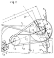
- the base 2 of a floor assembly is installed in the lower area of the housing 1 of a tumble dryer.
- the drive motor 3 for the laundry drum 4 rests therein, which in turn is rotatably mounted on the axis 5 on a housing component (not shown) which is arranged at a distance from the base 2.
- a lever 7 is also supported with one arm, in the operating position of which the axes of the fulcrum 6 and the drive motor 3 lie on a straight line 22 with the common axis 8 of the large pulley 9 and the countershaft sprocket 10.
- the common axis 8 is arranged in the vicinity of the free end 11 of the single-arm lever 7.
- the countershaft sprocket 10 is pulled into the drive belt 14 for the laundry drum 4 by this spring 12. As a result, the belt 14 remains under tension without any adjustment being required.
- the drum cross-sectional circular area 15 represents the drum pulley which is wrapped by the belt 14 and which is automatically in the same plane as the countershaft sprocket 10.
- the lever 7 is stretched by a compression spring 16 which is guided in a double-walled sleeve 17 so that the large pulley 9 has its lay belt 18 between them and the motor pinion 19 stretches.
- the countershaft belt 18 remains constantly tensioned without adjustment.
- the tension of the belts 14 and 18 is determined in part by the geometry of the countershaft parts and essentially by the tensioning forces of the springs 12 and 16.
- the rotational forces required for transmission from the motor to the large pulley 9 and from the countershaft sprocket 10 to the casing of the drum 4 determine the tension required for the belts 18 and 14.
- the tension for belt 18 is represented by vector F18 and the tension for belt 14 is represented by vector F14.
- the spring force F12 is broken down into the vector F2, which is the corresponding normal force on the straight line 22 at the point of application 20 of the point of intersection of the imaginary axis of the spring 12 and the straight line 22, and the vector F19, which ultimately results from the existing triangle of forces at the angle can be calculated.
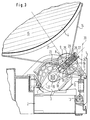
- FIG. 3 shows another embodiment for a drive device according to the invention.
- the one-armed lever 23 is not resiliently mounted at its pivot point 6; the lever 23 is rigid in itself. However, in the vicinity of its lever end 11 it has a link guide 24, which shows the central axis in the operating position of the lever 23 approximately on the axis of the motor 3.
- the link guide 24 receives a carriage 25 on which the bearing for the large pulley 9 and for the countershaft sprocket 10 is fastened. With this slide 25, the countershaft bearing can therefore be moved back and forth in the direction of the central axis of the link guide 24.
- the carriage 25 has at its end 26 protruding from the lever 23 a counter bearing bridge 27 for a compression spring 28 which is supported on a bearing plate 29 of the lever 23.
- the compression spring 28 therefore pulls the large pulley 9 over the countershaft bearing and the slide 25 into the belt 18.
- the countershaft sprocket 10 is pulled into the belt 14 by the tension spring 12 at the end 11 of the lever 23.
- FIG. 3 illustrated embodiment other spring tensions.
- the basic structure of the drive device according to the invention and the calculation process for the spring forces are, however, of the same type.
Landscapes
- Engineering & Computer Science (AREA)
- Textile Engineering (AREA)
- Devices For Conveying Motion By Means Of Endless Flexible Members (AREA)
- Detail Structures Of Washing Machines And Dryers (AREA)
Applications Claiming Priority (2)
| Application Number | Priority Date | Filing Date | Title |
|---|---|---|---|
| DE4438425A DE4438425B4 (de) | 1994-10-27 | 1994-10-27 | Antriebseinrichtung für einen Haushalt-Wäschetrockner |
| DE4438425 | 1994-10-27 |
Publications (2)
| Publication Number | Publication Date |
|---|---|
| EP0709515A1 true EP0709515A1 (fr) | 1996-05-01 |
| EP0709515B1 EP0709515B1 (fr) | 2001-05-23 |
Family
ID=6531860
Family Applications (1)
| Application Number | Title | Priority Date | Filing Date |
|---|---|---|---|
| EP95112317A Expired - Lifetime EP0709515B1 (fr) | 1994-10-27 | 1995-08-04 | Dispositif d'entraínement pour sèche-linge domestique |
Country Status (3)
| Country | Link |
|---|---|
| US (1) | US5694795A (fr) |
| EP (1) | EP0709515B1 (fr) |
| DE (2) | DE4438425B4 (fr) |
Cited By (3)
| Publication number | Priority date | Publication date | Assignee | Title |
|---|---|---|---|---|
| EP0903433A3 (fr) * | 1997-09-18 | 1999-07-21 | CANDY S.p.A. | Transmission à courroie , en particulier pour sèche linge et machines à laver |
| WO2001020071A1 (fr) * | 1999-09-15 | 2001-03-22 | Senkingwerk Gmbh | Systeme d'entrainement de tambour |
| DE102006061526A1 (de) | 2006-12-27 | 2008-07-03 | BSH Bosch und Siemens Hausgeräte GmbH | Antriebseinheit für einen Haushalt-Wäschetrockner |
Families Citing this family (7)
| Publication number | Priority date | Publication date | Assignee | Title |
|---|---|---|---|---|
| IT1289377B1 (it) * | 1996-05-22 | 1998-10-02 | Electrolux Zanussi Elettrodome | Dispositivo per il montaggio del motore in una macchina lavabiancheria |
| DE19728068B4 (de) * | 1997-07-01 | 2006-08-17 | BSH Bosch und Siemens Hausgeräte GmbH | Wäschetrockner |
| US5976043A (en) * | 1997-08-18 | 1999-11-02 | Hise; Neil R. | Apparatus for increasing wear life of machine members |
| US7168274B2 (en) * | 2003-05-05 | 2007-01-30 | American Dryer Corporation | Combination washer/dryer having common heat source |
| US7204774B2 (en) * | 2004-05-17 | 2007-04-17 | Emerson Electric Co. | One-piece drive pulley and belt guide |
| CN110594373B (zh) * | 2019-08-13 | 2024-02-13 | 上海海尔洗涤电器有限公司 | 一种皮带张紧机构、干衣机及干衣机的皮带的张紧方法 |
| KR102841287B1 (ko) * | 2020-06-22 | 2025-08-04 | 엘지전자 주식회사 | 의류처리장치 |
Citations (6)
| Publication number | Priority date | Publication date | Assignee | Title |
|---|---|---|---|---|
| US2506516A (en) | 1945-09-19 | 1950-05-02 | Hamilton Mfg Co | Laundry drier |
| US2716820A (en) | 1952-11-26 | 1955-09-06 | Temco Inc | Drying apparatus |
| US2814886A (en) * | 1954-12-27 | 1957-12-03 | Paul L Fowler | Clothes dryer |
| US3066422A (en) * | 1959-01-07 | 1962-12-04 | Blackstone Corp | Clothes driers |
| US3382587A (en) | 1966-09-06 | 1968-05-14 | Mc Graw Edison Co | Clothes conditioning-drying machine |
| DE2207372A1 (de) | 1972-02-17 | 1973-08-23 | Miele & Cie | Waeschetrockner mit umlaufender waeschetrommel |
Family Cites Families (1)
| Publication number | Priority date | Publication date | Assignee | Title |
|---|---|---|---|---|
| US2994216A (en) * | 1959-09-02 | 1961-08-01 | Westinghouse Electric Corp | Laundry apparatus |
-
1994
- 1994-10-27 DE DE4438425A patent/DE4438425B4/de not_active Expired - Fee Related
-
1995
- 1995-08-04 DE DE59509281T patent/DE59509281D1/de not_active Expired - Fee Related
- 1995-08-04 EP EP95112317A patent/EP0709515B1/fr not_active Expired - Lifetime
- 1995-10-27 US US08/549,058 patent/US5694795A/en not_active Expired - Fee Related
Patent Citations (6)
| Publication number | Priority date | Publication date | Assignee | Title |
|---|---|---|---|---|
| US2506516A (en) | 1945-09-19 | 1950-05-02 | Hamilton Mfg Co | Laundry drier |
| US2716820A (en) | 1952-11-26 | 1955-09-06 | Temco Inc | Drying apparatus |
| US2814886A (en) * | 1954-12-27 | 1957-12-03 | Paul L Fowler | Clothes dryer |
| US3066422A (en) * | 1959-01-07 | 1962-12-04 | Blackstone Corp | Clothes driers |
| US3382587A (en) | 1966-09-06 | 1968-05-14 | Mc Graw Edison Co | Clothes conditioning-drying machine |
| DE2207372A1 (de) | 1972-02-17 | 1973-08-23 | Miele & Cie | Waeschetrockner mit umlaufender waeschetrommel |
Cited By (4)
| Publication number | Priority date | Publication date | Assignee | Title |
|---|---|---|---|---|
| EP0903433A3 (fr) * | 1997-09-18 | 1999-07-21 | CANDY S.p.A. | Transmission à courroie , en particulier pour sèche linge et machines à laver |
| WO2001020071A1 (fr) * | 1999-09-15 | 2001-03-22 | Senkingwerk Gmbh | Systeme d'entrainement de tambour |
| DE102006061526A1 (de) | 2006-12-27 | 2008-07-03 | BSH Bosch und Siemens Hausgeräte GmbH | Antriebseinheit für einen Haushalt-Wäschetrockner |
| WO2008080826A1 (fr) * | 2006-12-27 | 2008-07-10 | BSH Bosch und Siemens Hausgeräte GmbH | Unité d'entraînement pour un sèche-linge à usage domestique |
Also Published As
| Publication number | Publication date |
|---|---|
| DE4438425A1 (de) | 1996-05-02 |
| EP0709515B1 (fr) | 2001-05-23 |
| US5694795A (en) | 1997-12-09 |
| DE59509281D1 (de) | 2001-06-28 |
| DE4438425B4 (de) | 2006-10-26 |
Similar Documents
| Publication | Publication Date | Title |
|---|---|---|
| DE3522591C2 (fr) | ||
| DE69008775T2 (de) | Seilscheibenanordnung eines selbstangetriebenen Aufzugs mit Anwendung eines Linearmotors auf dem Gegengewicht. | |
| EP0709515A1 (fr) | Dispositif d'entraînement pour sèche-linge domestique | |
| DE3340557C2 (fr) | ||
| WO2021110798A1 (fr) | Unité d'entraînement pour un ensemble coulissant, en particulier une porte coulissante | |
| DE4024666A1 (de) | Sektionaltor | |
| DE19636705C2 (de) | Motoreinheit für einen Wäschetrockner | |
| DE102005043891B4 (de) | Vorrichtung zum Hin- und Herbewegen eines Drahtes | |
| DE60126439T2 (de) | Farbenrührmaschine und befestigungsverfahren dafür | |
| DE102019121103A1 (de) | Bildschirmaufzugsanlage für Flachbildschirme zur Anordnung in Möbeln oder Einbaumöbeln | |
| DE2906991C2 (fr) | ||
| DE4225770C2 (de) | Haushalt-Wäschetrockner mit einer Treibriemen-Spannvorrichtung | |
| EP0226571A2 (fr) | Chaîne anti-neige | |
| CH428304A (de) | Vorrichtung zum Schütteln von Ästen | |
| DE3104568A1 (de) | Vorrichtung zum schliessen von tueren und toren, insbesondere schiebetoren | |
| DE29818095U1 (de) | Schnelllauftor | |
| DE19857669C2 (de) | Mechanische Anordnung zur Begrenzung der Bewegung von Arbeitsbühnen | |
| DE19517372A1 (de) | Trommel-Wäschetrockner mit Antriebsriemen und Spannwerk | |
| DE4028383A1 (de) | Waelz-linearfuehrung | |
| DE3728766C1 (en) | Test chamber | |
| WO2008080826A1 (fr) | Unité d'entraînement pour un sèche-linge à usage domestique | |
| DE2247708C3 (de) | Antrieb fUr eine Trommelwaschmaschine | |
| DE2410233C3 (de) | Vorrichtung zum Bewegen einer Ringbank einer Spinnmaschine | |
| AT220548B (de) | Mistlader | |
| DE202005013076U1 (de) | Kraftfahrzeugfensterheber |
Legal Events
| Date | Code | Title | Description |
|---|---|---|---|
| PUAI | Public reference made under article 153(3) epc to a published international application that has entered the european phase |
Free format text: ORIGINAL CODE: 0009012 |
|
| AK | Designated contracting states |
Kind code of ref document: A1 Designated state(s): CH DE FR GB LI NL SE |
|
| 17P | Request for examination filed |
Effective date: 19961024 |
|
| RAP1 | Party data changed (applicant data changed or rights of an application transferred) |
Owner name: BSH BOSCH UND SIEMENS HAUSGERAETE GMBH |
|
| 17Q | First examination report despatched |
Effective date: 19990201 |
|
| GRAG | Despatch of communication of intention to grant |
Free format text: ORIGINAL CODE: EPIDOS AGRA |
|
| GRAG | Despatch of communication of intention to grant |
Free format text: ORIGINAL CODE: EPIDOS AGRA |
|
| GRAH | Despatch of communication of intention to grant a patent |
Free format text: ORIGINAL CODE: EPIDOS IGRA |
|
| GRAH | Despatch of communication of intention to grant a patent |
Free format text: ORIGINAL CODE: EPIDOS IGRA |
|
| GRAA | (expected) grant |
Free format text: ORIGINAL CODE: 0009210 |
|
| AK | Designated contracting states |
Kind code of ref document: B1 Designated state(s): CH DE FR GB LI NL SE |
|
| REG | Reference to a national code |
Ref country code: CH Ref legal event code: NV Representative=s name: ISLER & PEDRAZZINI AG Ref country code: CH Ref legal event code: EP |
|
| GBT | Gb: translation of ep patent filed (gb section 77(6)(a)/1977) |
Effective date: 20010523 |
|
| REF | Corresponds to: |
Ref document number: 59509281 Country of ref document: DE Date of ref document: 20010628 |
|
| ET | Fr: translation filed | ||
| REG | Reference to a national code |
Ref country code: GB Ref legal event code: IF02 |
|
| PLBE | No opposition filed within time limit |
Free format text: ORIGINAL CODE: 0009261 |
|
| STAA | Information on the status of an ep patent application or granted ep patent |
Free format text: STATUS: NO OPPOSITION FILED WITHIN TIME LIMIT |
|
| 26N | No opposition filed | ||
| PGFP | Annual fee paid to national office [announced via postgrant information from national office to epo] |
Ref country code: NL Payment date: 20050818 Year of fee payment: 11 |
|
| PGFP | Annual fee paid to national office [announced via postgrant information from national office to epo] |
Ref country code: SE Payment date: 20050824 Year of fee payment: 11 |
|
| PG25 | Lapsed in a contracting state [announced via postgrant information from national office to epo] |
Ref country code: SE Free format text: LAPSE BECAUSE OF NON-PAYMENT OF DUE FEES Effective date: 20060805 |
|
| PG25 | Lapsed in a contracting state [announced via postgrant information from national office to epo] |
Ref country code: NL Free format text: LAPSE BECAUSE OF NON-PAYMENT OF DUE FEES Effective date: 20070301 |
|
| EUG | Se: european patent has lapsed | ||
| NLV4 | Nl: lapsed or anulled due to non-payment of the annual fee |
Effective date: 20070301 |
|
| REG | Reference to a national code |
Ref country code: CH Ref legal event code: PCAR Free format text: ISLER & PEDRAZZINI AG;POSTFACH 1772;8027 ZUERICH (CH) |
|
| PGFP | Annual fee paid to national office [announced via postgrant information from national office to epo] |
Ref country code: DE Payment date: 20080831 Year of fee payment: 14 Ref country code: CH Payment date: 20080825 Year of fee payment: 14 |
|
| PGFP | Annual fee paid to national office [announced via postgrant information from national office to epo] |
Ref country code: FR Payment date: 20080818 Year of fee payment: 14 |
|
| PGFP | Annual fee paid to national office [announced via postgrant information from national office to epo] |
Ref country code: GB Payment date: 20080822 Year of fee payment: 14 |
|
| REG | Reference to a national code |
Ref country code: CH Ref legal event code: PL |
|
| GBPC | Gb: european patent ceased through non-payment of renewal fee |
Effective date: 20090804 |
|
| PG25 | Lapsed in a contracting state [announced via postgrant information from national office to epo] |
Ref country code: LI Free format text: LAPSE BECAUSE OF NON-PAYMENT OF DUE FEES Effective date: 20090831 Ref country code: CH Free format text: LAPSE BECAUSE OF NON-PAYMENT OF DUE FEES Effective date: 20090831 |
|
| REG | Reference to a national code |
Ref country code: FR Ref legal event code: ST Effective date: 20100430 |
|
| PG25 | Lapsed in a contracting state [announced via postgrant information from national office to epo] |
Ref country code: FR Free format text: LAPSE BECAUSE OF NON-PAYMENT OF DUE FEES Effective date: 20090831 Ref country code: DE Free format text: LAPSE BECAUSE OF NON-PAYMENT OF DUE FEES Effective date: 20100302 |
|
| PG25 | Lapsed in a contracting state [announced via postgrant information from national office to epo] |
Ref country code: GB Free format text: LAPSE BECAUSE OF NON-PAYMENT OF DUE FEES Effective date: 20090804 |