EP0709519B1 - Tintenstrahldruckverfahren und Druck - Google Patents
Tintenstrahldruckverfahren und Druck Download PDFInfo
- Publication number
- EP0709519B1 EP0709519B1 EP95116762A EP95116762A EP0709519B1 EP 0709519 B1 EP0709519 B1 EP 0709519B1 EP 95116762 A EP95116762 A EP 95116762A EP 95116762 A EP95116762 A EP 95116762A EP 0709519 B1 EP0709519 B1 EP 0709519B1
- Authority
- EP
- European Patent Office
- Prior art keywords
- ink
- cloth
- printing
- jet printing
- water repellent
- Prior art date
- Legal status (The legal status is an assumption and is not a legal conclusion. Google has not performed a legal analysis and makes no representation as to the accuracy of the status listed.)
- Expired - Lifetime
Links
- 238000000034 method Methods 0.000 title claims abstract description 63
- 238000007641 inkjet printing Methods 0.000 title claims abstract description 34
- 239000004744 fabric Substances 0.000 claims abstract description 88
- 239000000976 ink Substances 0.000 claims abstract description 76
- 238000007639 printing Methods 0.000 claims abstract description 57
- XLYOFNOQVPJJNP-UHFFFAOYSA-N water Substances O XLYOFNOQVPJJNP-UHFFFAOYSA-N 0.000 claims abstract description 37
- 238000010521 absorption reaction Methods 0.000 claims abstract description 17
- 230000002940 repellent Effects 0.000 claims description 16
- 239000005871 repellent Substances 0.000 claims description 16
- 125000003504 2-oxazolinyl group Chemical class O1C(=NCC1)* 0.000 claims 2
- 239000004952 Polyamide Substances 0.000 claims 2
- JUJWROOIHBZHMG-UHFFFAOYSA-N Pyridine Chemical class C1=CC=NC=C1 JUJWROOIHBZHMG-UHFFFAOYSA-N 0.000 claims 2
- 239000004902 Softening Agent Substances 0.000 claims 2
- 150000001412 amines Chemical class 0.000 claims 2
- 239000000203 mixture Substances 0.000 claims 2
- 239000012188 paraffin wax Substances 0.000 claims 2
- 229920002647 polyamide Polymers 0.000 claims 2
- 150000003918 triazines Chemical class 0.000 claims 2
- 239000003086 colorant Substances 0.000 description 18
- RTZKZFJDLAIYFH-UHFFFAOYSA-N Diethyl ether Chemical compound CCOCC RTZKZFJDLAIYFH-UHFFFAOYSA-N 0.000 description 12
- 239000000975 dye Substances 0.000 description 12
- 239000003795 chemical substances by application Substances 0.000 description 11
- 239000000835 fiber Substances 0.000 description 10
- 230000008569 process Effects 0.000 description 10
- 150000001875 compounds Chemical class 0.000 description 7
- 125000000484 butyl group Chemical group [H]C([*])([H])C([H])([H])C([H])([H])C([H])([H])[H] 0.000 description 6
- 238000004040 coloring Methods 0.000 description 6
- 230000001276 controlling effect Effects 0.000 description 6
- 125000001495 ethyl group Chemical group [H]C([H])([H])C([H])([H])* 0.000 description 6
- 239000007788 liquid Substances 0.000 description 6
- 125000001436 propyl group Chemical group [H]C([*])([H])C([H])([H])C([H])([H])[H] 0.000 description 6
- 238000003860 storage Methods 0.000 description 6
- 239000004753 textile Substances 0.000 description 6
- LYCAIKOWRPUZTN-UHFFFAOYSA-N Ethylene glycol Chemical compound OCCO LYCAIKOWRPUZTN-UHFFFAOYSA-N 0.000 description 5
- DNIAPMSPPWPWGF-UHFFFAOYSA-N Propylene glycol Chemical compound CC(O)CO DNIAPMSPPWPWGF-UHFFFAOYSA-N 0.000 description 5
- 230000000740 bleeding effect Effects 0.000 description 5
- MTHSVFCYNBDYFN-UHFFFAOYSA-N diethylene glycol Chemical compound OCCOCCO MTHSVFCYNBDYFN-UHFFFAOYSA-N 0.000 description 5
- 238000001035 drying Methods 0.000 description 5
- -1 alkalis Substances 0.000 description 4
- 238000010276 construction Methods 0.000 description 4
- 230000035515 penetration Effects 0.000 description 4
- 239000000126 substance Substances 0.000 description 4
- 239000004094 surface-active agent Substances 0.000 description 4
- PEDCQBHIVMGVHV-UHFFFAOYSA-N Glycerine Chemical compound OCC(O)CO PEDCQBHIVMGVHV-UHFFFAOYSA-N 0.000 description 3
- 239000012790 adhesive layer Substances 0.000 description 3
- 239000012736 aqueous medium Substances 0.000 description 3
- 238000009792 diffusion process Methods 0.000 description 3
- 239000002657 fibrous material Substances 0.000 description 3
- 239000000463 material Substances 0.000 description 3
- 238000007650 screen-printing Methods 0.000 description 3
- MHXFWEJMQVIWDH-UHFFFAOYSA-N 1-amino-4-hydroxy-2-phenoxyanthracene-9,10-dione Chemical compound C1=C(O)C=2C(=O)C3=CC=CC=C3C(=O)C=2C(N)=C1OC1=CC=CC=C1 MHXFWEJMQVIWDH-UHFFFAOYSA-N 0.000 description 2
- 229920000742 Cotton Polymers 0.000 description 2
- SECXISVLQFMRJM-UHFFFAOYSA-N N-Methylpyrrolidone Chemical compound CN1CCCC1=O SECXISVLQFMRJM-UHFFFAOYSA-N 0.000 description 2
- 239000004677 Nylon Substances 0.000 description 2
- 229920000297 Rayon Polymers 0.000 description 2
- 239000000980 acid dye Substances 0.000 description 2
- 238000010420 art technique Methods 0.000 description 2
- 239000000982 direct dye Substances 0.000 description 2
- 239000000986 disperse dye Substances 0.000 description 2
- 230000000694 effects Effects 0.000 description 2
- PCHJSUWPFVWCPO-UHFFFAOYSA-N gold Chemical compound [Au] PCHJSUWPFVWCPO-UHFFFAOYSA-N 0.000 description 2
- 229910052737 gold Inorganic materials 0.000 description 2
- 239000010931 gold Substances 0.000 description 2
- 238000010438 heat treatment Methods 0.000 description 2
- 230000006872 improvement Effects 0.000 description 2
- 238000004519 manufacturing process Methods 0.000 description 2
- 229920001778 nylon Polymers 0.000 description 2
- 229920000728 polyester Polymers 0.000 description 2
- 229920001296 polysiloxane Chemical class 0.000 description 2
- 238000010926 purge Methods 0.000 description 2
- 239000002964 rayon Substances 0.000 description 2
- 239000000985 reactive dye Substances 0.000 description 2
- 238000010020 roller printing Methods 0.000 description 2
- 229910052709 silver Inorganic materials 0.000 description 2
- 239000004332 silver Substances 0.000 description 2
- 238000010025 steaming Methods 0.000 description 2
- 239000003021 water soluble solvent Substances 0.000 description 2
- 210000002268 wool Anatomy 0.000 description 2
- CYSGHNMQYZDMIA-UHFFFAOYSA-N 1,3-Dimethyl-2-imidazolidinon Chemical compound CN1CCN(C)C1=O CYSGHNMQYZDMIA-UHFFFAOYSA-N 0.000 description 1
- IXPNQXFRVYWDDI-UHFFFAOYSA-N 1-methyl-2,4-dioxo-1,3-diazinane-5-carboximidamide Chemical compound CN1CC(C(N)=N)C(=O)NC1=O IXPNQXFRVYWDDI-UHFFFAOYSA-N 0.000 description 1
- AZXGXVQWEUFULR-UHFFFAOYSA-N 2',4',5',7'-tetrabromofluorescein Chemical compound OC(=O)C1=CC=CC=C1C1=C2C=C(Br)C(=O)C(Br)=C2OC2=C(Br)C(O)=C(Br)C=C21 AZXGXVQWEUFULR-UHFFFAOYSA-N 0.000 description 1
- ROPYWXVRNREIQD-UHFFFAOYSA-N 2-[n-(2-cyanoethyl)-4-[(2,6-dichloro-4-nitrophenyl)diazenyl]anilino]ethyl acetate Chemical compound C1=CC(N(CCC#N)CCOC(=O)C)=CC=C1N=NC1=C(Cl)C=C([N+]([O-])=O)C=C1Cl ROPYWXVRNREIQD-UHFFFAOYSA-N 0.000 description 1
- SCLYXZFZPIKFAH-UHFFFAOYSA-N 2-[n-(2-cyanoethyl)-4-[(4-nitrophenyl)diazenyl]anilino]ethyl benzoate Chemical compound C1=CC([N+](=O)[O-])=CC=C1N=NC1=CC=C(N(CCOC(=O)C=2C=CC=CC=2)CCC#N)C=C1 SCLYXZFZPIKFAH-UHFFFAOYSA-N 0.000 description 1
- FOQABOMYTOFLPZ-UHFFFAOYSA-N 2-[n-ethyl-4-[(4-nitrophenyl)diazenyl]anilino]ethanol Chemical compound C1=CC(N(CCO)CC)=CC=C1N=NC1=CC=C([N+]([O-])=O)C=C1 FOQABOMYTOFLPZ-UHFFFAOYSA-N 0.000 description 1
- IHZXTIBMKNSJCJ-UHFFFAOYSA-N 3-{[(4-{[4-(dimethylamino)phenyl](4-{ethyl[(3-sulfophenyl)methyl]amino}phenyl)methylidene}cyclohexa-2,5-dien-1-ylidene)(ethyl)azaniumyl]methyl}benzene-1-sulfonate Chemical compound C=1C=C(C(=C2C=CC(C=C2)=[N+](C)C)C=2C=CC(=CC=2)N(CC)CC=2C=C(C=CC=2)S([O-])(=O)=O)C=CC=1N(CC)CC1=CC=CC(S(O)(=O)=O)=C1 IHZXTIBMKNSJCJ-UHFFFAOYSA-N 0.000 description 1
- AIARLPIXVMHZLJ-UHFFFAOYSA-N 4,8-diamino-2-bromo-1,5-dihydroxyanthracene-9,10-dione Chemical compound O=C1C2=C(N)C=C(Br)C(O)=C2C(=O)C2=C1C(O)=CC=C2N AIARLPIXVMHZLJ-UHFFFAOYSA-N 0.000 description 1
- QDPSGELUBXFKSB-UHFFFAOYSA-N 4-[(4-aminophenyl)diazenyl]naphthalen-1-amine Chemical compound C1=CC(N)=CC=C1N=NC1=CC=C(N)C2=CC=CC=C12 QDPSGELUBXFKSB-UHFFFAOYSA-N 0.000 description 1
- DUFCMRCMPHIFTR-UHFFFAOYSA-N 5-(dimethylsulfamoyl)-2-methylfuran-3-carboxylic acid Chemical class CN(C)S(=O)(=O)C1=CC(C(O)=O)=C(C)O1 DUFCMRCMPHIFTR-UHFFFAOYSA-N 0.000 description 1
- AVERNFJXXRIVQN-XSDYUOFFSA-N 5-[(4-ethoxyphenyl)diazenyl]-2-[(e)-2-[4-[(4-ethoxyphenyl)diazenyl]-2-sulfophenyl]ethenyl]benzenesulfonic acid Chemical compound C1=CC(OCC)=CC=C1N=NC(C=C1S(O)(=O)=O)=CC=C1\C=C\C1=CC=C(N=NC=2C=CC(OCC)=CC=2)C=C1S(O)(=O)=O AVERNFJXXRIVQN-XSDYUOFFSA-N 0.000 description 1
- 229920002972 Acrylic fiber Polymers 0.000 description 1
- 239000002202 Polyethylene glycol Substances 0.000 description 1
- 239000004372 Polyvinyl alcohol Substances 0.000 description 1
- YIQKLZYTHXTDDT-UHFFFAOYSA-H Sirius red F3B Chemical compound C1=CC(=CC=C1N=NC2=CC(=C(C=C2)N=NC3=C(C=C4C=C(C=CC4=C3[O-])NC(=O)NC5=CC6=CC(=C(C(=C6C=C5)[O-])N=NC7=C(C=C(C=C7)N=NC8=CC=C(C=C8)S(=O)(=O)[O-])S(=O)(=O)[O-])S(=O)(=O)O)S(=O)(=O)O)S(=O)(=O)[O-])S(=O)(=O)[O-].[Na+].[Na+].[Na+].[Na+].[Na+].[Na+] YIQKLZYTHXTDDT-UHFFFAOYSA-H 0.000 description 1
- XSQUKJJJFZCRTK-UHFFFAOYSA-N Urea Chemical compound NC(N)=O XSQUKJJJFZCRTK-UHFFFAOYSA-N 0.000 description 1
- KXXFHLLUPUAVRY-UHFFFAOYSA-J [Na+].[Na+].[Na+].[Cu++].[O-]C(=O)C1=CC=C(C=C1N=N[C-](N=NC1=C([O-])C(NC2=NC(F)=NC(NCCOCCS(=O)(=O)C=C)=N2)=CC(=C1)S([O-])(=O)=O)C1=CC=CC=C1)S([O-])(=O)=O Chemical compound [Na+].[Na+].[Na+].[Cu++].[O-]C(=O)C1=CC=C(C=C1N=N[C-](N=NC1=C([O-])C(NC2=NC(F)=NC(NCCOCCS(=O)(=O)C=C)=N2)=CC(=C1)S([O-])(=O)=O)C1=CC=CC=C1)S([O-])(=O)=O KXXFHLLUPUAVRY-UHFFFAOYSA-J 0.000 description 1
- 239000002253 acid Substances 0.000 description 1
- 150000007513 acids Chemical class 0.000 description 1
- 239000000654 additive Substances 0.000 description 1
- 230000000996 additive effect Effects 0.000 description 1
- 150000001346 alkyl aryl ethers Chemical class 0.000 description 1
- 150000005215 alkyl ethers Chemical class 0.000 description 1
- 239000003963 antioxidant agent Substances 0.000 description 1
- WXLFIFHRGFOVCD-UHFFFAOYSA-L azophloxine Chemical compound [Na+].[Na+].OC1=C2C(NC(=O)C)=CC(S([O-])(=O)=O)=CC2=CC(S([O-])(=O)=O)=C1N=NC1=CC=CC=C1 WXLFIFHRGFOVCD-UHFFFAOYSA-L 0.000 description 1
- VUXVWHOCQSLYRN-UHFFFAOYSA-O benzyl-[4-[[4-[benzyl(ethyl)amino]phenyl]-(2,4-disulfophenyl)methylidene]cyclohexa-2,5-dien-1-ylidene]-ethylazanium Chemical compound C=1C=C(C(=C2C=CC(C=C2)=[N+](CC)CC=2C=CC=CC=2)C=2C(=CC(=CC=2)S(O)(=O)=O)S(O)(=O)=O)C=CC=1N(CC)CC1=CC=CC=C1 VUXVWHOCQSLYRN-UHFFFAOYSA-O 0.000 description 1
- 230000015572 biosynthetic process Effects 0.000 description 1
- 239000007844 bleaching agent Substances 0.000 description 1
- 238000009835 boiling Methods 0.000 description 1
- 239000004202 carbamide Substances 0.000 description 1
- 239000000969 carrier Substances 0.000 description 1
- 239000003054 catalyst Substances 0.000 description 1
- 230000008859 change Effects 0.000 description 1
- ZBNARPCCDMHDDV-UHFFFAOYSA-N chembl1206040 Chemical compound C1=C(S(O)(=O)=O)C=C2C=C(S(O)(=O)=O)C(N=NC3=CC=C(C=C3C)C=3C=C(C(=CC=3)N=NC=3C(=CC4=CC(=CC(N)=C4C=3O)S(O)(=O)=O)S(O)(=O)=O)C)=C(O)C2=C1N ZBNARPCCDMHDDV-UHFFFAOYSA-N 0.000 description 1
- HFIYIRIMGZMCPC-UHFFFAOYSA-J chembl1326377 Chemical compound [Na+].[Na+].[Na+].[Na+].[O-]S(=O)(=O)C1=CC2=CC(S([O-])(=O)=O)=C(N=NC=3C=CC(=CC=3)S(=O)(=O)CCOS([O-])(=O)=O)C(O)=C2C(N)=C1N=NC1=CC=C(S(=O)(=O)CCOS([O-])(=O)=O)C=C1 HFIYIRIMGZMCPC-UHFFFAOYSA-J 0.000 description 1
- PXOZAFXVEWKXED-UHFFFAOYSA-N chembl1590721 Chemical compound C1=CC(NC(=O)C)=CC=C1N=NC1=CC(C)=CC=C1O PXOZAFXVEWKXED-UHFFFAOYSA-N 0.000 description 1
- 239000003638 chemical reducing agent Substances 0.000 description 1
- 230000000295 complement effect Effects 0.000 description 1
- 150000001983 dialkylethers Chemical class 0.000 description 1
- 238000007598 dipping method Methods 0.000 description 1
- 238000007599 discharging Methods 0.000 description 1
- JCGDEGCAEZOBSD-UHFFFAOYSA-L disodium 2-[4-[(2-hydroxynaphthalen-1-yl)diazenyl]-2-sulfonatophenyl]-5-[(3-methyl-5-oxo-1-phenyl-4H-pyrazol-4-yl)diazenyl]benzenesulfonate Chemical compound [Na+].[Na+].CC1=NN(C(=O)C1N=Nc1ccc(-c2ccc(cc2S([O-])(=O)=O)N=Nc2c(O)ccc3ccccc23)c(c1)S([O-])(=O)=O)c1ccccc1 JCGDEGCAEZOBSD-UHFFFAOYSA-L 0.000 description 1
- HWMSOVGCOJHRML-UHFFFAOYSA-L disodium 3-[[4-[(7-amino-1-hydroxy-3-sulfonatonaphthalen-2-yl)diazenyl]naphthalen-1-yl]diazenyl]-2,6-dihydroxybenzoate Chemical compound [Na+].[Na+].Nc1ccc2cc(c(N=Nc3ccc(N=Nc4ccc(O)c(C([O-])=O)c4O)c4ccccc34)c(O)c2c1)S([O-])(=O)=O HWMSOVGCOJHRML-UHFFFAOYSA-L 0.000 description 1
- UZZFFIUHUDOYPS-UHFFFAOYSA-L disodium 4-amino-3,6-bis[[4-[(2,4-diaminophenyl)diazenyl]phenyl]diazenyl]-5-oxido-7-sulfonaphthalene-2-sulfonate Chemical compound [Na+].[Na+].Nc1ccc(N=Nc2ccc(cc2)N=Nc2c(N)c3c(O)c(N=Nc4ccc(cc4)N=Nc4ccc(N)cc4N)c(cc3cc2S([O-])(=O)=O)S([O-])(=O)=O)c(N)c1 UZZFFIUHUDOYPS-UHFFFAOYSA-L 0.000 description 1
- DHQJMKJYFOHOSY-UHFFFAOYSA-L disodium 4-amino-3-[[4-[4-[(2,4-diaminophenyl)diazenyl]-3-methylphenyl]-2-methylphenyl]diazenyl]-5-oxido-6-phenyldiazenyl-7-sulfonaphthalene-2-sulfonate Chemical compound [Na+].[Na+].Cc1cc(ccc1N=Nc1ccc(N)cc1N)-c1ccc(N=Nc2c(N)c3c(O)c(N=Nc4ccccc4)c(cc3cc2S([O-])(=O)=O)S([O-])(=O)=O)c(C)c1 DHQJMKJYFOHOSY-UHFFFAOYSA-L 0.000 description 1
- DSARWKALPGYFTA-UHFFFAOYSA-L disodium 4-hydroxy-7-[(5-hydroxy-6-phenyldiazenyl-7-sulfonatonaphthalen-2-yl)carbamoylamino]-3-phenyldiazenylnaphthalene-2-sulfonate Chemical compound [Na+].[Na+].[O-]S(=O)(=O)C1=CC2=CC(NC(=O)NC=3C=C4C=C(C(N=NC=5C=CC=CC=5)=C(O)C4=CC=3)S([O-])(=O)=O)=CC=C2C(O)=C1N=NC1=CC=CC=C1 DSARWKALPGYFTA-UHFFFAOYSA-L 0.000 description 1
- WXUZMLVSQROLEX-UHFFFAOYSA-L disodium 5-[[4-[(4-anilino-3-sulfonatophenyl)diazenyl]naphthalen-1-yl]diazenyl]-6-hydroxynaphthalene-2-sulfonate Chemical compound [Na+].[Na+].Oc1ccc2cc(ccc2c1N=Nc1ccc(N=Nc2ccc(Nc3ccccc3)c(c2)S([O-])(=O)=O)c2ccccc12)S([O-])(=O)=O WXUZMLVSQROLEX-UHFFFAOYSA-L 0.000 description 1
- 239000002270 dispersing agent Substances 0.000 description 1
- 150000002222 fluorine compounds Chemical class 0.000 description 1
- 230000002209 hydrophobic effect Effects 0.000 description 1
- 125000002887 hydroxy group Chemical group [H]O* 0.000 description 1
- 239000004615 ingredient Substances 0.000 description 1
- 238000011835 investigation Methods 0.000 description 1
- 238000010409 ironing Methods 0.000 description 1
- 230000031700 light absorption Effects 0.000 description 1
- 230000007246 mechanism Effects 0.000 description 1
- 239000002609 medium Substances 0.000 description 1
- 229910052751 metal Inorganic materials 0.000 description 1
- 239000002184 metal Substances 0.000 description 1
- 229910021645 metal ion Inorganic materials 0.000 description 1
- MEMUMYCLWQPAEX-UHFFFAOYSA-N n-octadecylaziridine-1-carboxamide Chemical class CCCCCCCCCCCCCCCCCCNC(=O)N1CC1 MEMUMYCLWQPAEX-UHFFFAOYSA-N 0.000 description 1
- CTIQLGJVGNGFEW-UHFFFAOYSA-L naphthol yellow S Chemical compound [Na+].[Na+].C1=C(S([O-])(=O)=O)C=C2C([O-])=C([N+]([O-])=O)C=C([N+]([O-])=O)C2=C1 CTIQLGJVGNGFEW-UHFFFAOYSA-L 0.000 description 1
- 230000003287 optical effect Effects 0.000 description 1
- 239000007800 oxidant agent Substances 0.000 description 1
- 230000035699 permeability Effects 0.000 description 1
- 230000000704 physical effect Effects 0.000 description 1
- 229920001515 polyalkylene glycol Polymers 0.000 description 1
- 229920001223 polyethylene glycol Polymers 0.000 description 1
- 229920000098 polyolefin Chemical class 0.000 description 1
- 229920001451 polypropylene glycol Polymers 0.000 description 1
- 229920002451 polyvinyl alcohol Polymers 0.000 description 1
- 238000002360 preparation method Methods 0.000 description 1
- 230000002265 prevention Effects 0.000 description 1
- KXXXUIKPSVVSAW-UHFFFAOYSA-K pyranine Chemical compound [Na+].[Na+].[Na+].C1=C2C(O)=CC(S([O-])(=O)=O)=C(C=C3)C2=C2C3=C(S([O-])(=O)=O)C=C(S([O-])(=O)=O)C2=C1 KXXXUIKPSVVSAW-UHFFFAOYSA-K 0.000 description 1
- HNJBEVLQSNELDL-UHFFFAOYSA-N pyrrolidin-2-one Chemical compound O=C1CCCN1 HNJBEVLQSNELDL-UHFFFAOYSA-N 0.000 description 1
- 230000001105 regulatory effect Effects 0.000 description 1
- 230000004043 responsiveness Effects 0.000 description 1
- 239000004065 semiconductor Substances 0.000 description 1
- BQHRKYUXVHKLLZ-UHFFFAOYSA-M sodium 7-amino-2-[[4-[(4-aminophenyl)diazenyl]-2-methoxy-5-methylphenyl]diazenyl]-3-sulfonaphthalen-1-olate Chemical compound [Na+].COc1cc(N=Nc2ccc(N)cc2)c(C)cc1N=Nc1c(O)c2cc(N)ccc2cc1S([O-])(=O)=O BQHRKYUXVHKLLZ-UHFFFAOYSA-M 0.000 description 1
- 235000010413 sodium alginate Nutrition 0.000 description 1
- 239000000661 sodium alginate Substances 0.000 description 1
- 229940005550 sodium alginate Drugs 0.000 description 1
- FIXVWFINKCQNFG-UHFFFAOYSA-M sodium;4-[(4-aminophenyl)diazenyl]benzenesulfonate Chemical compound [Na+].C1=CC(N)=CC=C1N=NC1=CC=C(S([O-])(=O)=O)C=C1 FIXVWFINKCQNFG-UHFFFAOYSA-M 0.000 description 1
- GNFJBURFXWYRQN-UHFFFAOYSA-M sodium;4-[3-[[2-methyl-4-(4-methylphenyl)sulfonyloxyphenyl]diazenyl]anilino]-3-nitrobenzenesulfonate Chemical compound [Na+].C1=CC(C)=CC=C1S(=O)(=O)OC(C=C1C)=CC=C1N=NC1=CC=CC(NC=2C(=CC(=CC=2)S([O-])(=O)=O)[N+]([O-])=O)=C1 GNFJBURFXWYRQN-UHFFFAOYSA-M 0.000 description 1
- 239000007787 solid Substances 0.000 description 1
- 238000005507 spraying Methods 0.000 description 1
- HXJUTPCZVOIRIF-UHFFFAOYSA-N sulfolane Chemical compound O=S1(=O)CCCC1 HXJUTPCZVOIRIF-UHFFFAOYSA-N 0.000 description 1
- WNQPPENQFWLADQ-UHFFFAOYSA-J tetrasodium;4-hydroxy-5-[[4-[[4-[(8-hydroxy-3,6-disulfonatonaphthalen-1-yl)diazenyl]-2-methoxy-5-methylphenyl]carbamoylamino]-5-methoxy-2-methylphenyl]diazenyl]naphthalene-2,7-disulfonate Chemical compound [Na+].[Na+].[Na+].[Na+].[O-]S(=O)(=O)C1=CC(O)=C2C(N=NC3=C(C)C=C(C(=C3)OC)NC(=O)NC3=CC(C)=C(N=NC=4C5=C(O)C=C(C=C5C=C(C=4)S([O-])(=O)=O)S([O-])(=O)=O)C=C3OC)=CC(S([O-])(=O)=O)=CC2=C1 WNQPPENQFWLADQ-UHFFFAOYSA-J 0.000 description 1
- YODZTKMDCQEPHD-UHFFFAOYSA-N thiodiglycol Chemical compound OCCSCCO YODZTKMDCQEPHD-UHFFFAOYSA-N 0.000 description 1
- 229950006389 thiodiglycol Drugs 0.000 description 1
- ZIBGPFATKBEMQZ-UHFFFAOYSA-N triethylene glycol Chemical compound OCCOCCOCCO ZIBGPFATKBEMQZ-UHFFFAOYSA-N 0.000 description 1
- GWAKFAUFNNPZFE-UHFFFAOYSA-K trisodium 2-[4-[(2-amino-4-oxidophenyl)diazenyl]anilino]-5-[(1-amino-8-oxido-7-phenyldiazenyl-3,6-disulfonaphthalen-2-yl)diazenyl]benzenesulfonate Chemical compound NC1=C(C(=CC2=CC(=C(C(=C12)O)N=NC1=CC=CC=C1)S(=O)(=O)[O-])S(=O)(=O)[O-])N=NC1=CC(=C(C=C1)NC1=CC=C(C=C1)N=NC1=C(C=C(C=C1)O)N)S(=O)(=O)[O-].[Na+].[Na+].[Na+] GWAKFAUFNNPZFE-UHFFFAOYSA-K 0.000 description 1
- IHVXOVVDYSKGMH-UHFFFAOYSA-K trisodium 2-[[6-[(4-amino-6-chloro-1,3,5-triazin-2-yl)-methylamino]-1-hydroxy-3-sulfonatonaphthalen-2-yl]diazenyl]naphthalene-1,5-disulfonate Chemical compound [Na+].[Na+].[Na+].CN(c1ccc2c(O)c(N=Nc3ccc4c(cccc4c3S([O-])(=O)=O)S([O-])(=O)=O)c(cc2c1)S([O-])(=O)=O)c1nc(N)nc(Cl)n1 IHVXOVVDYSKGMH-UHFFFAOYSA-K 0.000 description 1
- QTFHTNFVUCUDIR-UHFFFAOYSA-K trisodium 6-[(2,4-diaminophenyl)diazenyl]-3-[[4-[4-[[7-[(2,4-diaminophenyl)diazenyl]-1-hydroxy-3-sulfonatonaphthalen-2-yl]diazenyl]-2-sulfonatoanilino]phenyl]diazenyl]-4-hydroxynaphthalene-2-sulfonate Chemical compound C1=CC(=CC=C1NC2=C(C=C(C=C2)N=NC3=C(C=C4C=CC(=CC4=C3[O-])N=NC5=C(C=C(C=C5)N)N)S(=O)(=O)O)S(=O)(=O)[O-])N=NC6=C(C=C7C=CC(=CC7=C6[O-])N=NC8=C(C=C(C=C8)N)N)S(=O)(=O)O.[Na+].[Na+].[Na+] QTFHTNFVUCUDIR-UHFFFAOYSA-K 0.000 description 1
- MBAYVHBJJXOOIY-UHFFFAOYSA-K trisodium 7-[[4-chloro-6-(3-sulfonatoanilino)-1,3,5-triazin-2-yl]-methylamino]-4-hydroxy-3-[(2-sulfonatophenyl)diazenyl]naphthalene-2-sulfonate Chemical compound [Na+].[Na+].[Na+].CN(c1ccc2c(O)c(N=Nc3ccccc3S([O-])(=O)=O)c(cc2c1)S([O-])(=O)=O)c1nc(Cl)nc(Nc2cccc(c2)S([O-])(=O)=O)n1 MBAYVHBJJXOOIY-UHFFFAOYSA-K 0.000 description 1
- WTPOYMNMKZIOGO-UHFFFAOYSA-K trisodium;2,5-dichloro-4-[4-[[5-[[4-chloro-6-(4-sulfonatoanilino)-1,3,5-triazin-2-yl]amino]-2-sulfonatophenyl]diazenyl]-3-methyl-5-oxo-4h-pyrazol-1-yl]benzenesulfonate Chemical compound [Na+].[Na+].[Na+].CC1=NN(C=2C(=CC(=C(Cl)C=2)S([O-])(=O)=O)Cl)C(=O)C1N=NC(C(=CC=1)S([O-])(=O)=O)=CC=1NC(N=1)=NC(Cl)=NC=1NC1=CC=C(S([O-])(=O)=O)C=C1 WTPOYMNMKZIOGO-UHFFFAOYSA-K 0.000 description 1
- QODWDUXKFKJVCQ-UHFFFAOYSA-K trisodium;2-[[4-[[4-[(4-amino-6-chloro-1,3,5-triazin-2-yl)amino]-5-sulfonatonaphthalen-1-yl]diazenyl]-2,5-dimethylphenyl]diazenyl]benzene-1,4-disulfonate Chemical compound [Na+].[Na+].[Na+].CC=1C=C(N=NC=2C(=CC=C(C=2)S([O-])(=O)=O)S([O-])(=O)=O)C(C)=CC=1N=NC(C1=CC=CC(=C11)S([O-])(=O)=O)=CC=C1NC1=NC(N)=NC(Cl)=N1 QODWDUXKFKJVCQ-UHFFFAOYSA-K 0.000 description 1
- DSKGJDYCSBLEMI-UHFFFAOYSA-K trisodium;7-[[4-[(4-amino-6-chloro-1,3,5-triazin-2-yl)amino]-2-(carbamoylamino)phenyl]diazenyl]naphthalene-1,3,6-trisulfonate Chemical compound [Na+].[Na+].[Na+].C=1C=C(N=NC=2C(=CC3=CC(=CC(=C3C=2)S([O-])(=O)=O)S([O-])(=O)=O)S([O-])(=O)=O)C(NC(=O)N)=CC=1NC1=NC(N)=NC(Cl)=N1 DSKGJDYCSBLEMI-UHFFFAOYSA-K 0.000 description 1
- 238000011144 upstream manufacturing Methods 0.000 description 1
- 239000004034 viscosity adjusting agent Substances 0.000 description 1
- 238000005406 washing Methods 0.000 description 1
- 238000004804 winding Methods 0.000 description 1
- 150000003755 zirconium compounds Chemical class 0.000 description 1
Images


Classifications
-
- B—PERFORMING OPERATIONS; TRANSPORTING
- B41—PRINTING; LINING MACHINES; TYPEWRITERS; STAMPS
- B41J—TYPEWRITERS; SELECTIVE PRINTING MECHANISMS, i.e. MECHANISMS PRINTING OTHERWISE THAN FROM A FORME; CORRECTION OF TYPOGRAPHICAL ERRORS
- B41J3/00—Typewriters or selective printing or marking mechanisms characterised by the purpose for which they are constructed
- B41J3/407—Typewriters or selective printing or marking mechanisms characterised by the purpose for which they are constructed for marking on special material
- B41J3/4078—Printing on textile
-
- D—TEXTILES; PAPER
- D06—TREATMENT OF TEXTILES OR THE LIKE; LAUNDERING; FLEXIBLE MATERIALS NOT OTHERWISE PROVIDED FOR
- D06P—DYEING OR PRINTING TEXTILES; DYEING LEATHER, FURS OR SOLID MACROMOLECULAR SUBSTANCES IN ANY FORM
- D06P1/00—General processes of dyeing or printing textiles, or general processes of dyeing leather, furs, or solid macromolecular substances in any form, classified according to the dyes, pigments, or auxiliary substances employed
- D06P1/0004—General aspects of dyeing
-
- D—TEXTILES; PAPER
- D06—TREATMENT OF TEXTILES OR THE LIKE; LAUNDERING; FLEXIBLE MATERIALS NOT OTHERWISE PROVIDED FOR
- D06P—DYEING OR PRINTING TEXTILES; DYEING LEATHER, FURS OR SOLID MACROMOLECULAR SUBSTANCES IN ANY FORM
- D06P5/00—Other features in dyeing or printing textiles, or dyeing leather, furs, or solid macromolecular substances in any form
- D06P5/001—Special chemical aspects of printing textile materials
-
- D—TEXTILES; PAPER
- D06—TREATMENT OF TEXTILES OR THE LIKE; LAUNDERING; FLEXIBLE MATERIALS NOT OTHERWISE PROVIDED FOR
- D06P—DYEING OR PRINTING TEXTILES; DYEING LEATHER, FURS OR SOLID MACROMOLECULAR SUBSTANCES IN ANY FORM
- D06P5/00—Other features in dyeing or printing textiles, or dyeing leather, furs, or solid macromolecular substances in any form
- D06P5/30—Ink jet printing
-
- B—PERFORMING OPERATIONS; TRANSPORTING
- B41—PRINTING; LINING MACHINES; TYPEWRITERS; STAMPS
- B41J—TYPEWRITERS; SELECTIVE PRINTING MECHANISMS, i.e. MECHANISMS PRINTING OTHERWISE THAN FROM A FORME; CORRECTION OF TYPOGRAPHICAL ERRORS
- B41J11/00—Devices or arrangements of selective printing mechanisms, e.g. ink-jet printers or thermal printers, for supporting or handling copy material in sheet or web form
- B41J11/0015—Devices or arrangements of selective printing mechanisms, e.g. ink-jet printers or thermal printers, for supporting or handling copy material in sheet or web form for treating before, during or after printing or for uniform coating or laminating the copy material before or after printing
- B41J11/002—Curing or drying the ink on the copy materials, e.g. by heating or irradiating
- B41J11/0021—Curing or drying the ink on the copy materials, e.g. by heating or irradiating using irradiation
- B41J11/00216—Curing or drying the ink on the copy materials, e.g. by heating or irradiating using irradiation using infrared [IR] radiation or microwaves
-
- B—PERFORMING OPERATIONS; TRANSPORTING
- B41—PRINTING; LINING MACHINES; TYPEWRITERS; STAMPS
- B41J—TYPEWRITERS; SELECTIVE PRINTING MECHANISMS, i.e. MECHANISMS PRINTING OTHERWISE THAN FROM A FORME; CORRECTION OF TYPOGRAPHICAL ERRORS
- B41J11/00—Devices or arrangements of selective printing mechanisms, e.g. ink-jet printers or thermal printers, for supporting or handling copy material in sheet or web form
- B41J11/0015—Devices or arrangements of selective printing mechanisms, e.g. ink-jet printers or thermal printers, for supporting or handling copy material in sheet or web form for treating before, during or after printing or for uniform coating or laminating the copy material before or after printing
- B41J11/002—Curing or drying the ink on the copy materials, e.g. by heating or irradiating
- B41J11/0022—Curing or drying the ink on the copy materials, e.g. by heating or irradiating using convection means, e.g. by using a fan for blowing or sucking air
Definitions
- the present invention relates to an ink-jet printing method by which a print excellent in gradation can be provided.
- ink-jet printing As a process for conducting printing on cloth.
- the ink-jet printing is a plateless system of which neither a screen nor an engraved roller is required, and is hence fit for the multi-kind small-quantity production.
- the techniques required of this ink-jet printing are greatly different from those of the screen or roller printing.
- Japanese Patent Application Laid-Open No. 4-59282 discloses an ink-jet printing cloth formed of a hydrophilic fiber material containing 0.1 to 3 % by weight of a surfactant.
- a surfactant a surfactant that is absorbed in the interior of fiber by diffusion, and so the travelling distance of the inks is comparatively short, and sharp bleeding is hence prevented to some extent.
- such a cloth is unfavorable to improvement in coloring ability because dyes penetrate into the interior of the fiber. Even if the shot-in ink quantity of an ink is increased with a view toward heightening color density, the ink is only absorbed in the interior of the cloth, and the color density on the surface of the cloth cannot be made high.
- the ink is absorbed in the interior of the cloth unless a substance for lengthening the time required to absorb water is applied to the cloth, and the color density on the surface of the cloth cannot be made high.
- the prior art techniques have been able to satisfy individual performance characteristics required of the ink-jet printing process for obtaining excellent prints to some extent, but have been unable to satisfy all the performance characteristics at the same time.
- EP-A-0 605 730 discloses an ink-jet printing method for the preparation of a printed cloth wherein the cloth is treated with a water repellent or a softening water repellent to adjust the water absorption to 5 to 240 seconds in accordance with JIS 1096A.
- Water repellents used in this document are fluorine compounds, silicone compounds and zirconium compounds.
- Softening and water repellents used include octadecylethyleneurea, zirconium acetate, polyolefine compounds, wax compounds, and silicone compounds.
- an ink-jet printing method comprising ejecting inks by an ink-jet printing apparatus to conduct printing on a cloth, wherein a cloth having water absorption of at least 3 seconds as determined by the method (dropping method) prescribed by JIS L-1096 A is used as said cloth, a shot-in ink quantity per unit area of the cloth is varied to obtain gradation control, and a water repellent as defined in claim 1 has been applied to the cloth.
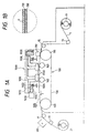
- Fig. 1A is a typical sectional side elevation schematically illustrating the constitution of an ink-jet printing apparatus to which the present invention is applied.
- Fig. 1B is an enlarged view of a portion of a conveyor belt in Fig. 1A.
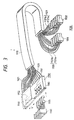
- Fig. 2 is a perspective view typically illustrating a printer section and a conveyance section in the apparatus shown in Fig. 1A.
- Fig. 3 is a typical perspective view of an ink-feeding system in the apparatus shown in Fig. 1A.
- Fig. 4 is a perspective view schematically illustrating the constitution of a printing head to be mounted on the apparatus shown in Fig. 1A.
- Fig. 5 is a graph illustrating a comparison between gradation and penetration of ink in a cloth.
- textile printing can be performed with excellent gradation in addition to excellent coloring ability and resistance to bleeding.
- the fiber material for the ink-jet printing cloth used in the present invention examples thereof include various fiber materials such as cotton, silk, wool, nylon, polyester, rayon and acrylic fibers.
- the cloth used may be a blended fabric or union cloth thereof.
- the water absorption which is an important factor in the present invention, was determined by measuring the water absorption time using, as a measuring means, the method (dropping method) prescribed by JIS L-1096 A.
- the antipenetrant means a substance which lowers the permeability of a cloth when added in a certain amount to the cloth as compared with the cloth before its addition.
- a softening water repellent or a water repellent is contained.
- any method such as padding, spraying, dipping, printing or ink-jet may be used.
- the softening water repellent or the water repellent used for controlling the penetration of ink has the ability to repel water which is a main component of ink. Examples thereof are defined in claim 1.
- the water repellent is applied in an amount of from 0.1 to 10 % by weight to a cloth so as to control the water absorption time of the cloth to at least 3 seconds, preferably within a range of from 10 seconds to 200 seconds. If the water absorption time is shorter than 3 seconds, the effect of controlling the penetration of ink becomes insufficient. When a cloth having water absorption of at least 3 seconds is used, inks are not absorbed in the interior of the fiber, but tend to remain on the surface of the fiber, and so the color density on the surface becomes high. Besides, when the water absorption is controlled to at most 200 seconds, the inks moderately penetrate in the interior of the fiber, and so excellent drying ability can be achieved.
- the cloth according to the present invention contains the above-described substances for the purpose of controlling its water absorption, but may also contain compounds other than these substances.
- compounds, which may be added to the cloth of the present invention include catalysts, alkalis, acids, antireductants, antioxidants, level dyeing agents, deep dyeing agents, carriers, reducing agents, oxidizing agents and metal ions.
- the thus-treated cloth is finally dried and optionally cut into sizes conveyable in an ink-jet apparatus, thereby providing these cut pieces as ink-jet printing cloths.
- the reactive dyes include C.I. Reactive Yellow 2, 15, 37, 42, 76, 95, 168 and 175; C.I. Reactive Red 21, 22, 24, 33, 45, 111, 112, 114, 180, 218, 226, 228 and 235; C.I. Reactive Blue 15, 19, 21, 38, 49, 72, 77, 176, 203, 220, 230 and 235; C.I. Reactive Orange 5, 12, 13, 35 and 95; C.I. Reactive Brown 7, 11, 33, 37 and 46; C.I. Reactive Green 8 and 19; C.I. Reactive Violet 2, 6 and 22; C.I. Reactive Black 5, 8, 31 and 39; and the like.
- the acid and direct dyes include C.I. Acid Yellow 1, 7, 11, 17, 23, 25, 36, 38, 49, 72, 110 and 127; C.I. Acid Red 1, 27, 35, 37, 57, 114, 138, 254, 257 and 274; C.I. Acid Blue 7, 9, 62, 83, 90, 112 and 185; C.I. Acid Black 26, 107, 109 and 155; C.I. Acid Orange 56, 67 and 149; C.I. Direct Yellow 12, 44, 50, 86, 106 and 142; C.I. Direct Red 79 and 80; C.I. Direct Blue 86, 106, 189 and 199; C.I. Direct Black 17, 19, 22, 51, 154, 168 and 173; C.I. Direct Orange 26 and 39; and the like.
- the disperse dyes include C.I. Disperse Yellow 3, 5, 7, 33, 42, 60, 64, 79, 104, 160, 163 and 237; C.I. Disperse Red 1, 60, 135, 145, 146 and 191; C.I. Disperse Blue 56, 60, 73, 143, 158, 198, 354, 365 and 366; C.I. Disperse Black 1 and 10; C.I. Disperse Orange 30 and 73; Teraprint Red 3GN Liquid and Teraprint Black 2R; and the like.
- the amount (in terms of solids) of these dyes to be used is preferably within a range of from 1 to 30 % by weight based on the total weight of the ink.
- water-soluble solvents used together with the dyes those generally used in ink-jet printing inks may be used.
- Preferable examples thereof include lower alkylene glycols such as ethylene glycol, diethylene glycol, triethylene glycol and propylene glycol; lower alkyl ethers of alkylene glycols, such as ethylene glycol methyl (ethyl, propyl or butyl) ether, diethylene glycol methyl (ethyl, propyl or butyl) ether, triethylene glycol methyl (ethyl, propyl or butyl) ether, propylene glycol methyl (ethyl, propyl or butyl) ether, dipropylene glycol methyl (ethyl, propyl or butyl) ether and tripropylene glycol methyl (ethyl, propyl or butyl) ether; polyalkylene glycols such as polyethylene glycol and polypropylene glycol and products obtained by modifying one or two
- the content of water as a principal component is preferably within a range of from 30 to 95 % by weight based on the total weight of the ink.
- anti-clogging agents such as urea and derivatives thereof, dispersants, surfactants, viscosity modifiers such as polyvinyl alcohol, cellulosic compounds and sodium alginate, pH adjustors, optical whitening agents, mildewproofing agents, and the like may be added as other ingredients for inks as needed.
- an ink-jet recording method and apparatus there may be used any method and apparatus conventionally known. Examples thereof include a method and an apparatus in which thermal energy corresponding to recording signals is applied to an ink within a recording head, and ink droplets are generated by this thermal energy.
- a method of controlling the diameter of a dot as a multi-valued technique
- a dither method or an error diffusion method as a two-valued technique.
- Fig. 5 there is shown recorded densities (K/S) obtained by using a cloth (A) the water absorption of which is at least 3 seconds as determined by the method of JIS L-1096 A and changing a shot-in ink quantity per unit area of the cloth in accordance with the dither method. For the sake of comparison, recorded densities as to a cloth (B) the water absorption of which is 1 second are also shown.
- the recorded density increases in substantial proportion to the shot-in ink quantity per unit area of the cloth. Therefore, excellent gradation is achieved from low color density to high color density.
- the recorded density no more increases after the shot-in ink quantity reaches a certain amount or more.
- the inks applied onto the ink-jet printing cloth in accordance with the method of the present invention in the above-described manner only adhere to the cloth in this state. Accordingly, it is preferable to subsequently subject the cloth to a process for fixing the dyes in the inks to fiber and a process for removing unfixed dyes.
- a fixing process may be conducted in accordance with any conventionally-known method. Examples thereof include a steaming process, an HT steaming process and a thermofix process.
- the removal of the unfixed dyes may be performed by any washing process conventionally known.
- the cloth After conducting the ink-jet printing and the posttreatment of the cloth in the above-described manner, the cloth is dried to provide a print according to the present invention.
- Fig. 1A is a typical sectional side elevation schematically illustrating the construction of a printing apparatus.
- Reference numeral 1 designates a cloth as a printing medium.
- the cloth 1 is unwound according to the rotation of a rewind roller 11, conveyed in a substantially horizontal direction by a conveyance section 100, which is provided at a position opposite to a printer section 1000, through intermediate rollers 13 and 15, and then wound up on a take-up roller 21 through a feed roller 17 and an intermediate roller 19.
- the conveyance section 100 roughly includes conveyance rollers 110 and 120 respectively provided on the upstream and downstream sides of the printer section 1000 viewing from the feeding direction of the cloth 1, a conveyor belt 130 in the form of an endless belt, which is extended between and around these rollers, and a pair of platen rollers 140 provided so as to extend the conveyor belt 130 under an appropriate tension in a predetermined range to enhance its evenness, thereby evenly regulating the surface of the cloth 1 to be printed by the printer section 1000.
- the conveyor belt 130 is made of a metal as disclosed in Japanese Patent Application Laid-Open No. 5-212851.
- an adhesive layer (sheet) 133 is provided on its surface. The cloth 1 is adhered to the conveyor belt 130 through the adhesive layer 133 by an attaching roller 150, thereby ensuring the evenness of the cloth 1 upon printing.
- a printing agent in the region between the platen rollers 140 by the printer section 1000.
- the thus-printed cloth 1 is separated from the conveyor belt 130, or the adhesive layer 133 at the position of the conveyance roller 120 and wound up on the take-up roller 21.
- the cloth is subjected to a drying treatment by a drying heater 600.
- this drying heater 600 is effective when a liquid agent is used as the printing agent.
- the form of the drying heater 600 may be suitably selected from a heater by which hot air is blown on the cloth 1, a heater by which infrared rays are applied to the cloth 1, and the like.
- Fig. 2 is a perspective view typically illustrating the printer section 1000 and the conveyance system of the cloth 1. The constitution of the printer section 1000 will be described with reference to this drawing and Fig. 1A.
- the printer section 1000 includes a carriage 1010 which scans in a direction different from the conveying direction (a secondary scanning direction) f of the cloth 1, for example, the width direction S of the cloth 1 perpendicular to the conveying direction f.
- Reference numeral 1020 designates a support rail extending in the S direction (a main scanning direction) and supporting a slide rail 1022 which supports and guides a slider 1012 fixed to the carriage 1010.
- Reference numeral 1030 indicates a motor as a drive source for conducting the main scanning of the carriage 1010. The driving power thereof is transmitted to the carriage 1010 through a belt 1032 to which the carriage 1010 has been fixed, or another suitable drive mechanism.
- the carriage 1010 On the carriage 1010, are mounted sets of printing heads 1100 each having many printing agent-applying elements arranged in a predetermined direction (in this case, the conveying direction f), said sets each being composed of a plurality of the printing heads 1100 arranged in a direction (in this case, the main scanning direction S) different from said predetermined direction.
- two sets of the printing heads 1100 are held in the conveying direction.
- the printing heads 1100 are provided in a number corresponding to the number of printing agents of different colors, thereby permitting color printing. Colors of the printing agents and the number of the printing heads in each set may be suitably selected according to an image intended to be formed on the cloth 1, and the like.
- yellow (Y), magenta (M) and cyan (C), or the three primary colors for printing, or black (Bk) in addition to these colors may make one set.
- special colors metallic colors such as gold and silver, and bright red, blue, etc.
- a plurality of printing agents may be used according to their color density even if they have the same colors as each other.
- two sets of the printing heads 1100 which each are composed of plural printing heads arranged in the main scanning direction S, are provided one by one in the conveying direction f.
- the colors, arranging number, arranging order and the like of the printing agents used in the printing heads in the respective sets may be the same or different from each other according to the image intended to be printed, and the like.
- printing may be made again by the printing heads of the second set on a region printed by main scanning of the printing heads of the first set (either complementary thinning-out printing or overlap printing may be conducted by the respective sets of the printing heads).
- a printing region may be allotted to each set to perform high-speed printing.
- the number of sets of the printing heads is not limited to two and may also be defined as one or more than two.
- ink-jet heads for example, bubble jet heads proposed by Canon Inc., each having a heating element which generates thermal energy causing film boiling of ink as energy used for ejecting the ink, are used as the printing heads 1100.
- Each of the printing heads is used in a state that ink ejection orifices as the printing agent-applying elements have been disposed downward toward the cloth substantially horizontally conveyed by the conveyance section 100, thereby ironing out the difference in water head between the individual ejection orifices and hence making ejection conditions uniform to permit both formation of good images and even purging operation for all the ejection orifices.
- a flexible cable 1110 is connected to each of the printing heads 1100 in such a manner that it follows the movement of the carriage 1010, so that various signals such as drive signals and state signals for the head are transferred between the head and control means not illustrated.
- Inks are fed from an ink-feeding system 1130, in which respective inks of different colors are contained, to the printing heads 1100 through flexible tubes 1120.
- Fig. 3 is a perspective view typically illustrating the ink-feeding system in this embodiment.
- the ink-feeding system 1130 is composed of two lines. More specifically, in the first line, first ink-feeding tubes 1120 respectively connected to the first set of ink-storage tanks 1131 are connected to a head joint 1150 through the flexible tube 1110. In the second line, similarly, second ink-feeding tubes 1121 respectively connected to the second set of ink-storage tanks 1132 are connected to the head joint 1150 through the flexible tube 1110.
- Each ink-feeding tube 1120 or 1121 forms a circulation path composed of an outward ink-feeding tube 1120a or 1121a and an inward ink-feeding tube 1120b or 1121b.
- the ink-storage tanks 1131 and 1132 each have a pressure pump (not illustrated).
- the ink in the tank 1131 or 1132 is pressurized by this pressure pump so as to pass through the outward ink-feeding tube 1120a or 1121a and ink connecter 1105 as illustrated in Fig. 3, circulate through the printing head 1100 and then pass through the inward ink-feeding tube 1120b or 1121b, thereby returning to the ink-storage tank 1131 or 1132.
- the ink-storage tanks 1131 and 1132 may be provided respectively by a number corresponding to the number of the printing agents of different colors, thereby permitting color printing.
- the number of the ink-storage tanks in each set may be suitably selected according to an image intended to be formed on the cloth 1, and the like. For example, three tanks for yellow (Y), magenta (M) and cyan (C) colors, or the three primary colors for printing, or four tanks with a tank for a black (Bk) color added to these tanks may be provided. Alternatively, tanks for special colors (metallic colors such as gold and silver, and bright red, blue, etc.), which are impossible or difficult to be expressed by the three primary colors, may be used in place of or in addition to the above tanks. Further, a plurality of tanks may be used according to the color density even if printing agents used have the same colors as each other.
- the head joint 1150 is composed of a head joint 1151 for the first set indicated by a full line in Fig. 3, a head joint 1152 for the second set indicated by a broken line in Fig. 3 and a joint cover 1160.
- Fig. 4 is a sectional perspective view schematically illustrating the construction of an ink-jet head to be mounted on the ink-jet printing apparatus used in the present invention.
- the printing head is constructed by overlapping a top plate 71 and a base plate 72.
- the top plate 71 has a plurality of grooves 73, which are to define nozzles passing an ink therethrough, a groove 74, which is to define a common liquid chamber communicating with these grooves, and a feed opening 75 for feeding the ink to the common liquid chamber.
- the base plate 72 includes electrothermal converters 76 corresponding to the individual nozzles and electrodes 77 for supplying electric power to the electrothermal converters 76, respectively, said electrothermal converters and electrodes being formed integrally by a film-forming technique.
- Ejection openings (orifices) 78 through which the ink is ejected are defined by overlapping the top plate 71 and the base plate 72 as described above.
- a heating resistor heats a predetermined temperature
- a filmy bubble as covers a heater surface
- the internal pressure of this bubble is very high, and so an ink within a nozzle is forced out.
- the ink is moved toward the outside of the nozzle and the interior of the common liquid chamber by inertia force by this forcing out.
- the moving speed of the ink within the nozzle becomes slow because the internal pressure of the bubble turns negative pressure, and flow path resistance also arises in addition.
- the ink portion ejected out of the ejection opening is faster in moving speed than the ink within the nozzle, it is constricted by the balance among inertia force, flow path resistance, shrinkage of the bubble and surface tension of the ink, whereby the ink portion is separated into a droplet.
- the ink is fed to the nozzle from the common liquid chamber by capillary force to wait for the next pulse.
- the printing head (hereinafter may be referred to as an ink-jet head), in which the electrothermal converter is used as an energy-generating means (hereinafter may be referred to as an energy-generatin element), can generate a bubble in the ink within the flow path in one-to-one correspondence in accordance with a driving electrical pulse signal and also immediately and appropriately cause the growth/shrinkage of the bubble, and so the ejection of ink droplets can be achieved with excellent responsiveness in particular.
- the electrothermal converter is used as an energy-generating means
- an energy-generatin element can generate a bubble in the ink within the flow path in one-to-one correspondence in accordance with a driving electrical pulse signal and also immediately and appropriately cause the growth/shrinkage of the bubble, and so the ejection of ink droplets can be achieved with excellent responsiveness in particular.
- the printing head is advantageous in that it can also be made compact with ease, merits of IC techniques and macro processing techniques in the recent semiconductor field, which are remarkable for advances in technique and enhancement in reliability, can be fully applied thereto, high-density mounting can be achieved with ease, and production costs are also low.
- an ink-jet printing method comprising ejecting inks by an ink-jet printing apparatus to conduct printing on a cloth, wherein a cloth having water absorption of at least 3 seconds as determined by the method (dropping method) prescribed by JIS L-1096 A is used as said cloth, a shot-in ink quantity per unit area of the cloth is changed to conduct gradation control, and wherein a water repellent as defined in claim 1 has been applied to the cloth.
Landscapes
- Engineering & Computer Science (AREA)
- Textile Engineering (AREA)
- Coloring (AREA)
- Ink Jet (AREA)
- Ink Jet Recording Methods And Recording Media Thereof (AREA)
Claims (4)
- Ein Tintenstrahldruckverfahren, umfassend das Ausstoßen von Tinten mittels einer Tintenstrahldruckvorrichtung, um ein Drucken auf einer Ware durchzuführen, wobei eine Ware mit einer Wasserabsorption von wenigstens 3 Sekunden, bestimmt durch das in der JIS L-1096 A beschriebene Abtropfverfahren, als die Ware eingesetzt wird, und wobei ein wasserabweisendes Mittel, einschließlich eines weichmachenden, wasserabweisenden Mittels, auf die Ware aufgebracht worden ist,
dadurch gekennzeichnet, dass
die Einschusstintenmenge pro Flächeneinheit der Ware variiert wird, um eine Steuerung der Abstufung zu erhalten, und
das wasserabweisende Mittel aus der Gruppe ausgewählt ist, bestehend aus Pyridiniumsalzen, N-Methylolalkylamiden, Oxazolinderivaten, Triazinverbindungen, Paraffin-Weichmachern vom Polyamidamin-Typ und deren Mischungen. - Das Tintenstrahldruckverfahren gemäß Anspruch 1, wobei das wasserabweisende Mittel in einer Menge von 0,1 bis 10 Gew.-%, basierend auf der Ware, aufgetragen wird.
- Das Tintenstrahldruckverfahren gemäß Anspruch 1, wobei die Tintenstrahldruckvorrichtung einen elektrothermischen Umwandler als eine Energieerzeugungseinrichtung zum Ausstoßen der Tinten umfasst.
- Eine bedruckte Ware, die ein wasserabweisendes Mittel enthält, ausgewählt aus der Gruppe, bestehend aus Pyridiniumsalzen, N-Methylolalkylamiden, Oxazolinderivaten, Triazinverbindungen, Paraffin-Weichmachern vom Polyamidamin-Typ und deren Mischungen, wobei die Ware durch das Verfahren gemäß irgendeinem der Ansprüche 1 bis 3 erhältlich ist.
Priority Applications (1)
| Application Number | Priority Date | Filing Date | Title |
|---|---|---|---|
| EP02000451A EP1215333A3 (de) | 1994-10-25 | 1995-10-24 | Tintenstrahldruckverfahren und Druck |
Applications Claiming Priority (6)
| Application Number | Priority Date | Filing Date | Title |
|---|---|---|---|
| JP260059/94 | 1994-10-25 | ||
| JP26005994 | 1994-10-25 | ||
| JP26005994 | 1994-10-25 | ||
| JP27135295 | 1995-10-19 | ||
| JP7271352A JPH08176973A (ja) | 1994-10-25 | 1995-10-19 | インクジェット捺染方法および捺染物 |
| JP271352/95 | 1995-10-19 |
Related Child Applications (2)
| Application Number | Title | Priority Date | Filing Date |
|---|---|---|---|
| EP02000451A Division EP1215333A3 (de) | 1994-10-25 | 1995-10-24 | Tintenstrahldruckverfahren und Druck |
| EP02000451.1 Division-Into | 2002-01-08 |
Publications (2)
| Publication Number | Publication Date |
|---|---|
| EP0709519A1 EP0709519A1 (de) | 1996-05-01 |
| EP0709519B1 true EP0709519B1 (de) | 2003-04-09 |
Family
ID=26544430
Family Applications (2)
| Application Number | Title | Priority Date | Filing Date |
|---|---|---|---|
| EP02000451A Withdrawn EP1215333A3 (de) | 1994-10-25 | 1995-10-24 | Tintenstrahldruckverfahren und Druck |
| EP95116762A Expired - Lifetime EP0709519B1 (de) | 1994-10-25 | 1995-10-24 | Tintenstrahldruckverfahren und Druck |
Family Applications Before (1)
| Application Number | Title | Priority Date | Filing Date |
|---|---|---|---|
| EP02000451A Withdrawn EP1215333A3 (de) | 1994-10-25 | 1995-10-24 | Tintenstrahldruckverfahren und Druck |
Country Status (6)
| Country | Link |
|---|---|
| US (1) | US6224204B1 (de) |
| EP (2) | EP1215333A3 (de) |
| JP (1) | JPH08176973A (de) |
| CN (1) | CN1075981C (de) |
| AT (1) | ATE237020T1 (de) |
| DE (1) | DE69530262D1 (de) |
Families Citing this family (29)
| Publication number | Priority date | Publication date | Assignee | Title |
|---|---|---|---|---|
| JPH1018184A (ja) * | 1996-05-02 | 1998-01-20 | Canon Inc | インクジェット捺染方法及び捺染物 |
| US6428159B1 (en) * | 1999-07-19 | 2002-08-06 | Xerox Corporation | Apparatus for achieving high quality aqueous ink-jet printing on plain paper at high print speeds |
| US6588954B2 (en) * | 2000-02-23 | 2003-07-08 | Agfa-Gevaert | Ink jet printer equipped for avoiding undesired belt movement |
| US6561642B2 (en) | 2001-09-28 | 2003-05-13 | Hewlett-Packard Development Company | Ink jet printer system for printing an image on a web overlaying a removable substrate and method of assembling the printer system |
| US6846076B2 (en) * | 2003-04-09 | 2005-01-25 | Milliken & Company | Methods employed in solvent-based ink jet printing |
| WO2004094149A2 (en) * | 2003-04-09 | 2004-11-04 | Milliken & Company | Products, compositions, and methods employed in solvent-based ink jet printing |
| US20040202801A1 (en) * | 2003-04-09 | 2004-10-14 | Milliken & Company | Products and compositions employed in solvent-based ink jet printing |
| ATE513024T1 (de) * | 2003-05-02 | 2011-07-15 | Canon Kk | Wässrige fluoreszenztinte, damit aufgenommenes bild sowie beurteilungsverfahren |
| US20040248492A1 (en) * | 2003-06-06 | 2004-12-09 | Reemay, Inc. | Nonwoven fabric printing medium and method of production |
| US20070103529A1 (en) * | 2003-06-16 | 2007-05-10 | Kornit Digital Ltd. | Process and system for printing images on absorptive surfaces |
| US11447648B2 (en) | 2004-05-30 | 2022-09-20 | Kornit Digital Ltd. | Process and system for printing images on absorptive surfaces |
| WO2006001546A1 (ja) * | 2004-06-28 | 2006-01-05 | Canon Kabushiki Kaisha | 分散性色材の製造方法及びインクジェット記録用インク |
| GB0505893D0 (en) * | 2005-03-22 | 2005-04-27 | Ten Cate Advanced Textiles Bv | Method for providing a water-repellant finish on a textile article |
| DE602007008908D1 (de) * | 2007-10-31 | 2010-10-14 | Xennia Holland Bv | Druckanordnung und Verfahren zur Ablagerung einer Substanz |
| CN104031476B (zh) | 2009-08-10 | 2017-05-03 | 柯尼特数码有限公司 | 用于可拉伸基材的喷墨组合物及方法 |
| JP5453681B2 (ja) * | 2010-02-12 | 2014-03-26 | 株式会社ミマキエンジニアリング | 画像形成装置及び画像形成方法 |
| US8926080B2 (en) | 2010-08-10 | 2015-01-06 | Kornit Digital Ltd. | Formaldehyde-free inkjet compositions and processes |
| CN102490466B (zh) * | 2011-12-06 | 2016-06-08 | 江南大学 | 一种多通道机头固定式平板数字喷墨印花机 |
| CN102514374B (zh) * | 2011-12-06 | 2016-04-13 | 江南大学 | 一种两喷头组平板式数字喷墨印花机 |
| JP6194674B2 (ja) * | 2013-07-29 | 2017-09-13 | セイコーエプソン株式会社 | 記録装置 |
| CN103935132B (zh) * | 2014-05-04 | 2016-05-04 | 长沙湘愿节能科技有限公司 | 一种双向联动七色独立式高速喷墨印花机 |
| CN105500924B (zh) * | 2016-02-14 | 2017-01-18 | 江南大学 | 一种三辊传动数字喷墨印花机 |
| CN105538929B (zh) * | 2016-02-14 | 2017-12-08 | 绍兴悦植贸易有限公司 | 一种多平板导带式数字喷墨印花装置和印花方法 |
| WO2018078634A1 (en) | 2016-10-31 | 2018-05-03 | Kornit Digital Ltd. | Dye-sublimation inkjet printing for textile |
| CN106995152B (zh) * | 2017-05-16 | 2019-02-22 | 嘉兴市前荣织造有限公司 | 一种纺织印染布料的喷雾印花装置 |
| JP2019025854A (ja) * | 2017-08-02 | 2019-02-21 | 株式会社ミマキエンジニアリング | プリンタ、印刷物の製造方法、及び、印刷物 |
| CN111511982A (zh) | 2017-10-22 | 2020-08-07 | 康丽数码有限公司 | 通过喷墨打印的低摩擦图像 |
| CN109808322B (zh) * | 2019-02-26 | 2021-02-26 | 浙江金晨纺织科技有限公司 | 一种热转纸张的凹版印刷方法 |
| CN110849249B (zh) * | 2019-11-28 | 2021-12-17 | 济宁天久工贸有限公司 | 一种缝纫部位平整度和抗拉扯强度检测装置 |
Citations (1)
| Publication number | Priority date | Publication date | Assignee | Title |
|---|---|---|---|---|
| EP0693587A2 (de) * | 1994-07-21 | 1996-01-24 | Canon Kabushiki Kaisha | Tintenstrahldruckgewebe, Tintenstrahldruckverfahren und Verfahren zur Herstellung von Drucken |
Family Cites Families (9)
| Publication number | Priority date | Publication date | Assignee | Title |
|---|---|---|---|---|
| GB2187137B (en) * | 1986-02-07 | 1990-10-17 | Canon Kk | Recording medium and recording method which makes use thereof |
| JP2932621B2 (ja) | 1990-06-28 | 1999-08-09 | 東レ株式会社 | インクジェット染色用布帛ならびにそれを用いてなるインクジェット染色方法 |
| JP2818991B2 (ja) * | 1991-11-01 | 1998-10-30 | 鐘紡株式会社 | 捺染布帛 |
| JP2713685B2 (ja) * | 1991-12-27 | 1998-02-16 | キヤノン株式会社 | インクジェット捺染方法、同方法で捺染され布帛、及び捺染された布帛の製造方法 |
| JP2952128B2 (ja) * | 1992-01-27 | 1999-09-20 | キヤノン株式会社 | インクジェット捺染用布帛、インクジェット捺染方法及び捺染物 |
| JP2736484B2 (ja) | 1992-02-05 | 1998-04-02 | 鐘紡株式会社 | 捺染装置 |
| EP0605730B1 (de) * | 1992-07-27 | 2005-11-30 | Kanebo, Ltd. | Bedruckter stoff und verfahren zur herstellung |
| CA2113960C (en) * | 1993-01-29 | 2001-07-31 | Kazuyoshi Takahashi | Image supply apparatus, image output apparatus, control apparatus therefor, and image forming system having these apparatuses |
| US5515093A (en) * | 1993-06-25 | 1996-05-07 | Canon Kabushiki Kaisha | Ink jet printing method and print medium for use in the method |
-
1995
- 1995-10-19 JP JP7271352A patent/JPH08176973A/ja active Pending
- 1995-10-24 DE DE69530262T patent/DE69530262D1/de not_active Expired - Lifetime
- 1995-10-24 EP EP02000451A patent/EP1215333A3/de not_active Withdrawn
- 1995-10-24 EP EP95116762A patent/EP0709519B1/de not_active Expired - Lifetime
- 1995-10-24 US US08/547,463 patent/US6224204B1/en not_active Expired - Fee Related
- 1995-10-24 AT AT95116762T patent/ATE237020T1/de not_active IP Right Cessation
- 1995-10-25 CN CN95117659A patent/CN1075981C/zh not_active Expired - Fee Related
Patent Citations (1)
| Publication number | Priority date | Publication date | Assignee | Title |
|---|---|---|---|---|
| EP0693587A2 (de) * | 1994-07-21 | 1996-01-24 | Canon Kabushiki Kaisha | Tintenstrahldruckgewebe, Tintenstrahldruckverfahren und Verfahren zur Herstellung von Drucken |
Also Published As
| Publication number | Publication date |
|---|---|
| EP0709519A1 (de) | 1996-05-01 |
| ATE237020T1 (de) | 2003-04-15 |
| JPH08176973A (ja) | 1996-07-09 |
| US6224204B1 (en) | 2001-05-01 |
| CN1126666A (zh) | 1996-07-17 |
| EP1215333A3 (de) | 2010-06-30 |
| EP1215333A2 (de) | 2002-06-19 |
| DE69530262D1 (de) | 2003-05-15 |
| CN1075981C (zh) | 2001-12-12 |
Similar Documents
| Publication | Publication Date | Title |
|---|---|---|
| EP0709519B1 (de) | Tintenstrahldruckverfahren und Druck | |
| EP0693587B1 (de) | Tintenstrahldruckgewebe, Tintenstrahldruckverfahren und Verfahren zur Herstellung von Drucken | |
| EP0790347B1 (de) | Tintenstrahldruckgewebe, Tintenstrahldruckverfahren und Druck | |
| EP0879912B1 (de) | Verfahren und Vorrichtung zum Tintenstrahldrucken von Textilgut | |
| KR100392578B1 (ko) | 날염 방법, 이 방법에 의해 수득된 날염물 및 가공품 | |
| JP2000248217A (ja) | インクジェット記録方法、及び該方法により得られる記録物 | |
| US6153263A (en) | Ink jet textile printing and printing textile article | |
| JPH0885219A (ja) | インクジェットプリント装置、インクジェットプリント方法およびプリント物 | |
| JP3164868B2 (ja) | インクジェット捺染方法 | |
| US6863359B2 (en) | Ink-jet printing apparatus and ink-jet printing method | |
| JP3315532B2 (ja) | インクジェット捺染用布帛およびその製造方法、インクジェット捺染方法、インクジェット捺染物および捺染記録物 | |
| EP0693588B1 (de) | Textildruckverfahren sowie damit hergestellte bedruckte Textilien | |
| EP0790346B1 (de) | Tintenstrahldruckgewebe, Tintenstrahldruckverfahren und Druck | |
| JP2004169248A (ja) | インクジェット捺染方法、インクジェット捺染装置 | |
| JP3501519B2 (ja) | インクジェット捺染用布帛、インクジェット捺染方法およびインクジェット捺染物 | |
| JPH1053973A (ja) | インクジェット捺染用編物、その製造方法、インクジェット捺染方法、および、インクジェット捺染物 | |
| JPH10331078A (ja) | インクジェット染色用布帛、それを用いたインクジェット染色方法およびインクジェット染色物 | |
| JPH08232176A (ja) | インクジェット捺染方法および同方法により記録された捺染物 | |
| JP2704590B2 (ja) | インクジェット印捺法 | |
| JP2003293272A (ja) | インクジェット捺染方法 | |
| JPH08127980A (ja) | インクジェット捺染用布帛、インクジェット捺染方法およびインクジェット捺染物 | |
| JPH08127978A (ja) | インクジェット捺染用布帛、インクジェット捺染方法およびインクジェット捺染物 | |
| JP3295117B2 (ja) | 捺染方法 | |
| JPH11179931A (ja) | インクジェットプリント装置およびインクジェットプリント方法 |
Legal Events
| Date | Code | Title | Description |
|---|---|---|---|
| PUAI | Public reference made under article 153(3) epc to a published international application that has entered the european phase |
Free format text: ORIGINAL CODE: 0009012 |
|
| AK | Designated contracting states |
Kind code of ref document: A1 Designated state(s): AT BE CH DE DK ES FR GB GR IE IT LI LU MC NL PT SE |
|
| 17P | Request for examination filed |
Effective date: 19960617 |
|
| 17Q | First examination report despatched |
Effective date: 20000105 |
|
| GRAH | Despatch of communication of intention to grant a patent |
Free format text: ORIGINAL CODE: EPIDOS IGRA |
|
| GRAH | Despatch of communication of intention to grant a patent |
Free format text: ORIGINAL CODE: EPIDOS IGRA |
|
| GRAA | (expected) grant |
Free format text: ORIGINAL CODE: 0009210 |
|
| AK | Designated contracting states |
Designated state(s): AT BE CH DE DK ES FR GB GR IE IT LI LU MC NL PT SE |
|
| PG25 | Lapsed in a contracting state [announced via postgrant information from national office to epo] |
Ref country code: NL Free format text: LAPSE BECAUSE OF FAILURE TO SUBMIT A TRANSLATION OF THE DESCRIPTION OR TO PAY THE FEE WITHIN THE PRESCRIBED TIME-LIMIT Effective date: 20030409 Ref country code: LI Free format text: LAPSE BECAUSE OF FAILURE TO SUBMIT A TRANSLATION OF THE DESCRIPTION OR TO PAY THE FEE WITHIN THE PRESCRIBED TIME-LIMIT Effective date: 20030409 Ref country code: IT Free format text: LAPSE BECAUSE OF FAILURE TO SUBMIT A TRANSLATION OF THE DESCRIPTION OR TO PAY THE FEE WITHIN THE PRESCRIBED TIME-LIMIT;WARNING: LAPSES OF ITALIAN PATENTS WITH EFFECTIVE DATE BEFORE 2007 MAY HAVE OCCURRED AT ANY TIME BEFORE 2007. THE CORRECT EFFECTIVE DATE MAY BE DIFFERENT FROM THE ONE RECORDED. Effective date: 20030409 Ref country code: FR Free format text: LAPSE BECAUSE OF FAILURE TO SUBMIT A TRANSLATION OF THE DESCRIPTION OR TO PAY THE FEE WITHIN THE PRESCRIBED TIME-LIMIT Effective date: 20030409 Ref country code: CH Free format text: LAPSE BECAUSE OF FAILURE TO SUBMIT A TRANSLATION OF THE DESCRIPTION OR TO PAY THE FEE WITHIN THE PRESCRIBED TIME-LIMIT Effective date: 20030409 Ref country code: BE Free format text: LAPSE BECAUSE OF FAILURE TO SUBMIT A TRANSLATION OF THE DESCRIPTION OR TO PAY THE FEE WITHIN THE PRESCRIBED TIME-LIMIT Effective date: 20030409 Ref country code: AT Free format text: LAPSE BECAUSE OF FAILURE TO SUBMIT A TRANSLATION OF THE DESCRIPTION OR TO PAY THE FEE WITHIN THE PRESCRIBED TIME-LIMIT Effective date: 20030409 |
|
| REG | Reference to a national code |
Ref country code: GB Ref legal event code: FG4D |
|
| REG | Reference to a national code |
Ref country code: CH Ref legal event code: EP |
|
| REG | Reference to a national code |
Ref country code: IE Ref legal event code: FG4D |
|
| PG25 | Lapsed in a contracting state [announced via postgrant information from national office to epo] |
Ref country code: SE Free format text: LAPSE BECAUSE OF FAILURE TO SUBMIT A TRANSLATION OF THE DESCRIPTION OR TO PAY THE FEE WITHIN THE PRESCRIBED TIME-LIMIT Effective date: 20030709 Ref country code: PT Free format text: LAPSE BECAUSE OF FAILURE TO SUBMIT A TRANSLATION OF THE DESCRIPTION OR TO PAY THE FEE WITHIN THE PRESCRIBED TIME-LIMIT Effective date: 20030709 Ref country code: GR Free format text: LAPSE BECAUSE OF FAILURE TO SUBMIT A TRANSLATION OF THE DESCRIPTION OR TO PAY THE FEE WITHIN THE PRESCRIBED TIME-LIMIT Effective date: 20030709 Ref country code: DK Free format text: LAPSE BECAUSE OF FAILURE TO SUBMIT A TRANSLATION OF THE DESCRIPTION OR TO PAY THE FEE WITHIN THE PRESCRIBED TIME-LIMIT Effective date: 20030709 |
|
| PG25 | Lapsed in a contracting state [announced via postgrant information from national office to epo] |
Ref country code: DE Free format text: LAPSE BECAUSE OF FAILURE TO SUBMIT A TRANSLATION OF THE DESCRIPTION OR TO PAY THE FEE WITHIN THE PRESCRIBED TIME-LIMIT Effective date: 20030710 |
|
| NLV1 | Nl: lapsed or annulled due to failure to fulfill the requirements of art. 29p and 29m of the patents act | ||
| REG | Reference to a national code |
Ref country code: CH Ref legal event code: PL |
|
| PG25 | Lapsed in a contracting state [announced via postgrant information from national office to epo] |
Ref country code: LU Free format text: LAPSE BECAUSE OF NON-PAYMENT OF DUE FEES Effective date: 20031024 Ref country code: IE Free format text: LAPSE BECAUSE OF NON-PAYMENT OF DUE FEES Effective date: 20031024 |
|
| PG25 | Lapsed in a contracting state [announced via postgrant information from national office to epo] |
Ref country code: ES Free format text: LAPSE BECAUSE OF FAILURE TO SUBMIT A TRANSLATION OF THE DESCRIPTION OR TO PAY THE FEE WITHIN THE PRESCRIBED TIME-LIMIT Effective date: 20031030 |
|
| PG25 | Lapsed in a contracting state [announced via postgrant information from national office to epo] |
Ref country code: MC Free format text: LAPSE BECAUSE OF NON-PAYMENT OF DUE FEES Effective date: 20031031 |
|
| PLBE | No opposition filed within time limit |
Free format text: ORIGINAL CODE: 0009261 |
|
| STAA | Information on the status of an ep patent application or granted ep patent |
Free format text: STATUS: NO OPPOSITION FILED WITHIN TIME LIMIT |
|
| EN | Fr: translation not filed | ||
| 26N | No opposition filed |
Effective date: 20040112 |
|
| REG | Reference to a national code |
Ref country code: IE Ref legal event code: MM4A |
|
| PGFP | Annual fee paid to national office [announced via postgrant information from national office to epo] |
Ref country code: GB Payment date: 20081029 Year of fee payment: 14 |
|
| PG25 | Lapsed in a contracting state [announced via postgrant information from national office to epo] |
Ref country code: GB Free format text: LAPSE BECAUSE OF NON-PAYMENT OF DUE FEES Effective date: 20091024 |