EP0709529A1 - Système de filtre d'eaux résiduaires et le procédé résultant pour la reduction d'impuretés tamisables des dispositifs de décharge de réseaux d'égouts et réservoirs de clarification - Google Patents
Système de filtre d'eaux résiduaires et le procédé résultant pour la reduction d'impuretés tamisables des dispositifs de décharge de réseaux d'égouts et réservoirs de clarification Download PDFInfo
- Publication number
- EP0709529A1 EP0709529A1 EP94103491A EP94103491A EP0709529A1 EP 0709529 A1 EP0709529 A1 EP 0709529A1 EP 94103491 A EP94103491 A EP 94103491A EP 94103491 A EP94103491 A EP 94103491A EP 0709529 A1 EP0709529 A1 EP 0709529A1
- Authority
- EP
- European Patent Office
- Prior art keywords
- fabric filter
- area
- filter web
- systems
- weir
- Prior art date
- Legal status (The legal status is an assumption and is not a legal conclusion. Google has not performed a legal analysis and makes no representation as to the accuracy of the status listed.)
- Granted
Links
Images



Classifications
-
- E—FIXED CONSTRUCTIONS
- E03—WATER SUPPLY; SEWERAGE
- E03F—SEWERS; CESSPOOLS
- E03F5/00—Sewerage structures
- E03F5/12—Emergency outlets
-
- E—FIXED CONSTRUCTIONS
- E03—WATER SUPPLY; SEWERAGE
- E03F—SEWERS; CESSPOOLS
- E03F5/00—Sewerage structures
- E03F5/14—Devices for separating liquid or solid substances from sewage, e.g. sand or sludge traps, rakes or grates
Definitions
- FIG. 1 shows a longitudinal section of a mixed water collector in which the dry weather water level ( 18 ) lies below the fabric filter web ( 1 ) and the weir upper edge ( 26 ) has been raised to the maximum water level position (7).
- a relief system ( 25 ) is arranged between the inlet-side inspection shaft axis "AA” and the outlet-side inspection shaft axis "DD” in the region of an axis "CC” displaced off-center in the direction of flow ( 27 ). It can be seen how the fabric filter web ( 1 ) in the slide rails in the defined channel area ( 3 ) ( 2 ) should be retracted and locked.
- the entire fabric filter web ( 1 ) consists of several individual surfaces ( 20 ) which are connected to one another by means of point connections ( 21 ) and ultimately in the start area ( 4 ) or in the end area ( 5 ) via a corresponding curve formation ( 6 ) up to the maximum water level ( 7 ), which means that the entire relief space ( 23 ) can only be covered with filtered mixed water in the event of a dam.
- Fig. 2 shows a longitudinal section of a mixed water collector in the relief state, in which the maximum water level position ( 7 ) in the constructive entrance area ( 4 ) was assumed.
- the indicated relief activity by lowering the upper weir edge ( 26) of the controllable weir ( 24 ) lowers the energy line in the area of the relief system ( 25 ) by the differential pressure ( 28 ), which results from the sum of the pipe friction losses and filter resistances, etc.
- the arching of the fabric filter web ( 1 ) shown, which ultimately reveals the flexing effect and the resulting self-cleaning of the fabric filter web ( 1 ).
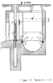
- Fig. 3 shows a cross section of the mixed water collector "CC" in which the sensible arrangement of the fabric filter web ( 1 ) can be seen within the relief system ( 25 ).
- the controllable weir ( 24 ) is lowered and is in the so-called relief case, with excess waste water being drained off towards the receiving water.
- the wastewater flows through the fabric filter web ( 1 ) due to the differential pressure ( 28 ) occurring from the different absolute water levels in the sewer and relief chamber ( 23 ) and thus creates an upward curvature of the fabric filter web ( 1 ), which ultimately results in the flexing effect becomes recognizable.
- the floating baffle ( 22 ) has the task of holding back any light material in the mixing system that has passed through the fabric filter web ( 1 ). Furthermore, it can also be seen that in the weir area ( 9 ) of relief systems ( 25 ) at least one slide rail ( 2 ) must always be locked below the fixed weir edge ( 29 ), so that a seamless reduction of sievable dirt loads from mixing systems or mixed water clarifiers can be made possible.
- Fig. 4 shows a cross section of the mixed water collector "AA" in the direction of flow ( 27 ), in which the sensible locking of a fabric filter web ( 1 ) by means of its side edges ( 11 ) located tensile sliding elements ( 13 ), which in turn within the parallel slide rails ( 2 ), here designed like half rails, are drawn in and are subject to a reversible arrangement. Furthermore, it can be seen that the fabric filter web ( 1 ) is pulled up to the maximum water level position ( 7 ) by means of the slide rails ( 2 ) located in the vertical outer wall areas ( 19 ), shown here in broken lines, so that the mixed water quantities flowing to the relief chamber ( 23 ) procedurally differ from those can be exempted from screenable dirt loads.
- the fabric filter sheet ( 1 ) due to its own weight, has a sag [DH] ( 16 ) in this representation and clarifies the fact of claim 5, according to which the maximum dry weather water level ( 18 ) should normally be below the fabric filter sheet ( 1 ) .
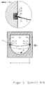
- Fig. 5 shows a cross section of the mixed water collector "BB" in which the dry weather water level ( 18 ) is below the then sagging by the weight of the fabric filter web ( 1 ), whereby it must be necessary that the width ( 14 ) of the fabric filter web ( 1 ) is greater than that Pipe profile width ( 15 ).
- a possible variant for reversible locking of the fabric filter web ( 1 ) is shown in detail 3.1, wherein it can be seen that the fabric filter web ( 1 ) has reinforcements ( 12 ) on its edges ( 11 ), on which the tensile sliding element ( 13 ) acts as a slide shoe formed is located within the slide rail ( 1 ).
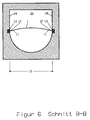
- Fig. 6 shows a cross section of the mixed water collector "BB" in which due to a relief by lowering the weir ( 24 ) not shown here or in the case of mixed water accumulation and thus increased inlet water levels, the fabric filter web ( 1 ) is curved upwards. It can be seen here that as a result of the flow through the fabric filter web ( 1 ) from the bottom upwards, reinforcements ( 12 ) with tension-resistant sliding elements ( 13 ) are necessary at their lateral edges ( 11 ) so that a force can be transmitted to the sliding rails ( 2 ) .
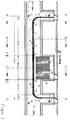
- Fig. 7 shows a top view "EE" a section through the relief system ( 25 ) in which the arrangement of the individual surfaces ( 20 ) of the fabric filter webs ( 1 ) and the arrangement of the eyelet connections ( 21 ) together with the slide rails ( 2 ) is shown.
Landscapes
- Health & Medical Sciences (AREA)
- Life Sciences & Earth Sciences (AREA)
- Engineering & Computer Science (AREA)
- Hydrology & Water Resources (AREA)
- Public Health (AREA)
- Water Supply & Treatment (AREA)
- Business, Economics & Management (AREA)
- Emergency Management (AREA)
- Filtration Of Liquid (AREA)
- Filtering Materials (AREA)
Priority Applications (2)
| Application Number | Priority Date | Filing Date | Title |
|---|---|---|---|
| DE59401781T DE59401781D1 (de) | 1994-03-08 | 1994-03-08 | Abwasserfiltersystem und daraus resultierendes Verfahren zur Reduzierung siebbarer Schmutzfrachtanteile an Entlastungsanlagen von Mischsystemen und Mischwasserklärbecken |
| EP19940103491 EP0709529B1 (fr) | 1994-03-08 | 1994-03-08 | Système de filtre d'eaux résiduaires et le procédé résultant pour la reduction d'impuretés tamisables des dispositifs de décharge de réseaux d'égouts et réservoirs de clarification |
Applications Claiming Priority (1)
| Application Number | Priority Date | Filing Date | Title |
|---|---|---|---|
| EP19940103491 EP0709529B1 (fr) | 1994-03-08 | 1994-03-08 | Système de filtre d'eaux résiduaires et le procédé résultant pour la reduction d'impuretés tamisables des dispositifs de décharge de réseaux d'égouts et réservoirs de clarification |
Publications (2)
| Publication Number | Publication Date |
|---|---|
| EP0709529A1 true EP0709529A1 (fr) | 1996-05-01 |
| EP0709529B1 EP0709529B1 (fr) | 1997-02-05 |
Family
ID=8215750
Family Applications (1)
| Application Number | Title | Priority Date | Filing Date |
|---|---|---|---|
| EP19940103491 Expired - Lifetime EP0709529B1 (fr) | 1994-03-08 | 1994-03-08 | Système de filtre d'eaux résiduaires et le procédé résultant pour la reduction d'impuretés tamisables des dispositifs de décharge de réseaux d'égouts et réservoirs de clarification |
Country Status (2)
| Country | Link |
|---|---|
| EP (1) | EP0709529B1 (fr) |
| DE (1) | DE59401781D1 (fr) |
Cited By (2)
| Publication number | Priority date | Publication date | Assignee | Title |
|---|---|---|---|---|
| GB2365797A (en) * | 2000-08-09 | 2002-02-27 | Uponor Ltd | Combined Sewer overflow |
| WO2002077379A1 (fr) * | 2001-03-07 | 2002-10-03 | Vollmar Gmbh | Installation d'epuration des eaux usees equipee d'un dispositif de purification |
Citations (3)
| Publication number | Priority date | Publication date | Assignee | Title |
|---|---|---|---|---|
| DE376338C (de) * | 1921-12-15 | 1923-05-28 | Eugen Geiger Dr | Notauslassklaeranlage |
| DE2743580A1 (de) * | 1977-09-28 | 1979-03-29 | Herbert Reppert | Spuelrechen fuer regenentlastungen in mischwasserkanaelen |
| WO1992021837A1 (fr) * | 1991-05-30 | 1992-12-10 | Kevin John Banner | Deflecteur de debris et procede de filtration |
-
1994
- 1994-03-08 EP EP19940103491 patent/EP0709529B1/fr not_active Expired - Lifetime
- 1994-03-08 DE DE59401781T patent/DE59401781D1/de not_active Expired - Fee Related
Patent Citations (3)
| Publication number | Priority date | Publication date | Assignee | Title |
|---|---|---|---|---|
| DE376338C (de) * | 1921-12-15 | 1923-05-28 | Eugen Geiger Dr | Notauslassklaeranlage |
| DE2743580A1 (de) * | 1977-09-28 | 1979-03-29 | Herbert Reppert | Spuelrechen fuer regenentlastungen in mischwasserkanaelen |
| WO1992021837A1 (fr) * | 1991-05-30 | 1992-12-10 | Kevin John Banner | Deflecteur de debris et procede de filtration |
Cited By (4)
| Publication number | Priority date | Publication date | Assignee | Title |
|---|---|---|---|---|
| GB2365797A (en) * | 2000-08-09 | 2002-02-27 | Uponor Ltd | Combined Sewer overflow |
| GB2365797B (en) * | 2000-08-09 | 2003-07-16 | Uponor Ltd | Combined sewer overflow |
| WO2002077379A1 (fr) * | 2001-03-07 | 2002-10-03 | Vollmar Gmbh | Installation d'epuration des eaux usees equipee d'un dispositif de purification |
| US7674371B2 (en) | 2001-03-07 | 2010-03-09 | Frank Rainer Kolb | Waste water installation with purification device |
Also Published As
| Publication number | Publication date |
|---|---|
| EP0709529B1 (fr) | 1997-02-05 |
| DE59401781D1 (de) | 1997-03-20 |
Similar Documents
| Publication | Publication Date | Title |
|---|---|---|
| EP3309310B1 (fr) | Trop-plein d'eaux pluviales destiné à les collecter et stocker | |
| DE2039422B2 (de) | Schraegklaerer | |
| DE102010003633B4 (de) | Vorrichtung und Verfahren zum Klären von Abwasser von Sediment | |
| DE3117061C2 (fr) | ||
| EP3791027B1 (fr) | Unité de rigole de corps de remplissage, système de rigole de corps de remplissage et éléments de regard | |
| AT395968B (de) | Tauchwand fuer regen- und klaerbecken | |
| DE202014101152U1 (de) | Entwässerungsrinnenelement | |
| DE2831501A1 (de) | Vorrichtung zum sammeln und abraeumen von schlamm | |
| AT400599B (de) | Siebrechenanordnung für überlaufbecken | |
| DE3403718C2 (fr) | ||
| EP0509422B1 (fr) | Dispositif de commande de déversement et de niveau d'eau d'installations hydrauliques | |
| DE3333883C2 (fr) | ||
| DE102010040645A1 (de) | Abwasserbehandlungsvorrichtung und Abwasserbehandlungsanlage mit einer derartigen Abwasserbehandlungsvorrichtung | |
| EP0709529B1 (fr) | Système de filtre d'eaux résiduaires et le procédé résultant pour la reduction d'impuretés tamisables des dispositifs de décharge de réseaux d'égouts et réservoirs de clarification | |
| EP0767278B1 (fr) | Système de caniveau pour l'infiltration d'eau | |
| AT398960B (de) | Steckfiltereinheit und anlage zum abscheiden von leichtflüssigkeiten | |
| DE19618300C2 (de) | Durchströmte Tauchwand | |
| AT400734B (de) | Tauchwandanordnung in einer regenwasseranlage | |
| DE102017109276A1 (de) | Ablaufschacht sowie Tauchbogen, Separationswandung und Umlenkplatte hierfür | |
| DE102007016487B4 (de) | Flüssigkeitsreinigungsvorrichtung mit einer Steueranordnung | |
| AT398959B (de) | Anlage zum abscheiden von leichtflüssigkeiten, insb. mineralölen | |
| DE19520565C2 (de) | Vorrichtung zur Ableitung von geklärtem Abwasser aus Absetzbecken von Kläranlagen | |
| EP2405063B1 (fr) | Agencement de traitement d'eaux usées | |
| DE202011104877U1 (de) | Entwässerungs-Rinnensystem | |
| DE3910848A1 (de) | Einrichtung zum regulieren des ablaufs aus einem ausgleichsbehaelter, z. b. einem regenrueckhaltebecken |
Legal Events
| Date | Code | Title | Description |
|---|---|---|---|
| PUAI | Public reference made under article 153(3) epc to a published international application that has entered the european phase |
Free format text: ORIGINAL CODE: 0009012 |
|
| 17P | Request for examination filed |
Effective date: 19950513 |
|
| AK | Designated contracting states |
Kind code of ref document: A1 Designated state(s): DE FR GB IT |
|
| GRAG | Despatch of communication of intention to grant |
Free format text: ORIGINAL CODE: EPIDOS AGRA |
|
| GRAH | Despatch of communication of intention to grant a patent |
Free format text: ORIGINAL CODE: EPIDOS IGRA |
|
| GRAH | Despatch of communication of intention to grant a patent |
Free format text: ORIGINAL CODE: EPIDOS IGRA |
|
| GRAA | (expected) grant |
Free format text: ORIGINAL CODE: 0009210 |
|
| AK | Designated contracting states |
Kind code of ref document: B1 Designated state(s): DE FR GB IT |
|
| REF | Corresponds to: |
Ref document number: 59401781 Country of ref document: DE Date of ref document: 19970320 |
|
| ITF | It: translation for a ep patent filed | ||
| GBT | Gb: translation of ep patent filed (gb section 77(6)(a)/1977) |
Effective date: 19970408 |
|
| ET | Fr: translation filed | ||
| PLBE | No opposition filed within time limit |
Free format text: ORIGINAL CODE: 0009261 |
|
| STAA | Information on the status of an ep patent application or granted ep patent |
Free format text: STATUS: NO OPPOSITION FILED WITHIN TIME LIMIT |
|
| 26N | No opposition filed | ||
| PGFP | Annual fee paid to national office [announced via postgrant information from national office to epo] |
Ref country code: GB Payment date: 20010315 Year of fee payment: 8 |
|
| REG | Reference to a national code |
Ref country code: GB Ref legal event code: IF02 |
|
| PG25 | Lapsed in a contracting state [announced via postgrant information from national office to epo] |
Ref country code: GB Free format text: LAPSE BECAUSE OF NON-PAYMENT OF DUE FEES Effective date: 20020308 |
|
| PGFP | Annual fee paid to national office [announced via postgrant information from national office to epo] |
Ref country code: FR Payment date: 20020617 Year of fee payment: 9 |
|
| GBPC | Gb: european patent ceased through non-payment of renewal fee |
Effective date: 20020308 |
|
| PGFP | Annual fee paid to national office [announced via postgrant information from national office to epo] |
Ref country code: DE Payment date: 20030325 Year of fee payment: 10 |
|
| PG25 | Lapsed in a contracting state [announced via postgrant information from national office to epo] |
Ref country code: FR Free format text: LAPSE BECAUSE OF NON-PAYMENT OF DUE FEES Effective date: 20031127 |
|
| REG | Reference to a national code |
Ref country code: FR Ref legal event code: ST |
|
| PG25 | Lapsed in a contracting state [announced via postgrant information from national office to epo] |
Ref country code: DE Free format text: LAPSE BECAUSE OF NON-PAYMENT OF DUE FEES Effective date: 20041001 |
|
| PG25 | Lapsed in a contracting state [announced via postgrant information from national office to epo] |
Ref country code: IT Free format text: LAPSE BECAUSE OF NON-PAYMENT OF DUE FEES;WARNING: LAPSES OF ITALIAN PATENTS WITH EFFECTIVE DATE BEFORE 2007 MAY HAVE OCCURRED AT ANY TIME BEFORE 2007. THE CORRECT EFFECTIVE DATE MAY BE DIFFERENT FROM THE ONE RECORDED. Effective date: 20050308 |