EP0709533A2 - Serrure cylindrique à goupille électromagnétique - Google Patents
Serrure cylindrique à goupille électromagnétique Download PDFInfo
- Publication number
- EP0709533A2 EP0709533A2 EP95116755A EP95116755A EP0709533A2 EP 0709533 A2 EP0709533 A2 EP 0709533A2 EP 95116755 A EP95116755 A EP 95116755A EP 95116755 A EP95116755 A EP 95116755A EP 0709533 A2 EP0709533 A2 EP 0709533A2
- Authority
- EP
- European Patent Office
- Prior art keywords
- pin
- lock cylinder
- locking
- housing
- particular according
- Prior art date
- Legal status (The legal status is an assumption and is not a legal conclusion. Google has not performed a legal analysis and makes no representation as to the accuracy of the status listed.)
- Granted
Links
- 238000003780 insertion Methods 0.000 claims description 9
- 230000037431 insertion Effects 0.000 claims description 9
- 230000004913 activation Effects 0.000 claims description 3
- 230000005540 biological transmission Effects 0.000 claims description 2
- 239000004020 conductor Substances 0.000 claims 1
- 238000007654 immersion Methods 0.000 claims 1
- 238000011161 development Methods 0.000 description 2
- 230000018109 developmental process Effects 0.000 description 2
- 230000000694 effects Effects 0.000 description 2
- 230000001681 protective effect Effects 0.000 description 2
- 229910000831 Steel Inorganic materials 0.000 description 1
- 238000013459 approach Methods 0.000 description 1
- 238000013475 authorization Methods 0.000 description 1
- 230000008859 change Effects 0.000 description 1
- 230000000295 complement effect Effects 0.000 description 1
- 238000006073 displacement reaction Methods 0.000 description 1
- 230000005284 excitation Effects 0.000 description 1
- 230000010354 integration Effects 0.000 description 1
- 239000002184 metal Substances 0.000 description 1
- 238000000034 method Methods 0.000 description 1
- 230000008569 process Effects 0.000 description 1
- 230000004044 response Effects 0.000 description 1
- 239000011343 solid material Substances 0.000 description 1
- 239000010959 steel Substances 0.000 description 1
- 239000013589 supplement Substances 0.000 description 1
Images


Classifications
-
- E—FIXED CONSTRUCTIONS
- E05—LOCKS; KEYS; WINDOW OR DOOR FITTINGS; SAFES
- E05B—LOCKS; ACCESSORIES THEREFOR; HANDCUFFS
- E05B47/00—Operating or controlling locks or other fastening devices by electric or magnetic means
- E05B47/06—Controlling mechanically-operated bolts by electro-magnetically-operated detents
- E05B47/0611—Cylinder locks with electromagnetic control
- E05B47/0619—Cylinder locks with electromagnetic control by blocking the rotor
- E05B47/0626—Cylinder locks with electromagnetic control by blocking the rotor radially
- E05B47/063—Cylinder locks with electromagnetic control by blocking the rotor radially with a rectilinearly moveable blocking element
-
- E—FIXED CONSTRUCTIONS
- E05—LOCKS; KEYS; WINDOW OR DOOR FITTINGS; SAFES
- E05B—LOCKS; ACCESSORIES THEREFOR; HANDCUFFS
- E05B47/00—Operating or controlling locks or other fastening devices by electric or magnetic means
- E05B47/0001—Operating or controlling locks or other fastening devices by electric or magnetic means with electric actuators; Constructional features thereof
- E05B47/0002—Operating or controlling locks or other fastening devices by electric or magnetic means with electric actuators; Constructional features thereof with electromagnets
- E05B47/0003—Operating or controlling locks or other fastening devices by electric or magnetic means with electric actuators; Constructional features thereof with electromagnets having a movable core
- E05B47/0004—Operating or controlling locks or other fastening devices by electric or magnetic means with electric actuators; Constructional features thereof with electromagnets having a movable core said core being linearly movable
Definitions
- the invention relates to a locking cylinder according to the preamble of claim 1.
- Such a locking cylinder is known from the published patent application 41 26 160.
- the known locking cylinder has pin tumblers that interact with the profile of the key and consist of a core pin and a housing pin.
- the tumbler pins spring-loaded towards the housing are arranged by the notches in the key, so that with the correct key, the joints between the core pin and the housing pin are aligned with the core joint of the cylinder core.
- electronic coding is provided.
- electronically activatable elements of the key act together with a transmitting / receiving device which, if the electronic key coding is correct, releases an additional locking pin which protrudes into the cylinder core.
- the locking pin is parallel to the pin tumblers. The arrangement is space-consuming. Either a longer locking cylinder has to be provided or a mechanically codable pin tumbler has to be dispensed with.
- the object of the invention is to further develop a generic locking cylinder in a manner which is advantageous for use.
- the space requirement of the additional locking pin has been considerably minimized.
- the locking pin is preferably arranged in a hollow of the housing pin of the pin tumbler. It is advantageous if the locking pin is arranged in the tumbler which is furthest away from the key insertion opening. The possibility of manipulation is thus minimized. It is advantageous if the locking pin, which is guided coaxially in the housing pin, projects at one end in the locking position into an axial blind hole in the core pin.
- the additional locking pin can be cushioned.
- the spring of the locking pin can simultaneously be the cushioning of the housing pin of the associated pin tumbler.
- the locking pin preferably has a widened foot on which the said spring is supported.
- the base of the locking pin preferably interacts with an armature of an electromagnet which can be mounted parallel to the axial direction of the cylinder core.
- the armature can be displaced in the axial direction by applying current to the electromagnet or an actuating element having the same effect.
- the armature is preferably cylindrically symmetrical and has a large-diameter and a small-diameter area.
- the cross section of the armature can also have a shape that deviates from the cylindrical shape. This makes it possible to increase the stroke of the locking pin.
- the two areas with different diameters can be separated from one another by a frustoconical area.
- the locking pin can then be moved in the transverse direction by axially displacing the armature be shifted to the cylinder axis so that its front end is shifted into the cylinder core to achieve the locking effect, or is shifted out of the cylinder core to achieve the release position.
- the electromagnet is preferably arranged in a sleeve which is arranged in the flange area of the profile cylinder. The sleeve simultaneously forms the bottom of the housing bores in which the pin tumblers lie. This novel closure of the pin hole has its own meaning. Instead of the axially insertable sleeve, a bolt or the like made of solid material is also conceivable.
- the housing section with which the bores are closed then simultaneously forms a support surface for the pin springs.
- An antenna of a transmitter is preferably provided on the flange end, which cooperates with a transponder arranged in the cover of the key.
- a device for example a contact or the like, can also be provided in the area of the transmitter, which allows an emergency opening of the lock by, for example, coded actuation. The emergency opening can also be done mechanically.
- the transmitter which is to cooperate with the transponder arranged in the cover of the key, is preferably switched on by shifting the tumbler pin that was first shifted by the key during the insertion movement.
- the housing pin closest to the end face of the locking cylinder takes over the activation by a switching process.
- the transponder can have a magnet which interacts with a magnetic switch which is arranged in the sleeve.
- this pin tumbler is first shifted downwards.
- the approach of the magnet to the magnetic switch then causes the transmitter to start up and transmit signals to the transponder.
- the signals can be on a Carrier frequency be modulated.
- the carrier frequency can also represent the energy supply for the transponder at the same time.
- the signal received by the transponder which can also consist only of an electromagnetic carrier for energy transmission, causes the transponder to send a response signal to the locking cylinder. This signal then carries the coding.
- the antenna arranged in the flange area of the locking cylinder receives the signal emitted by the transponder and forwards it to an electronic circuit, which is preferably arranged outside the profile cylinder.
- an electronic circuit which is preferably arranged outside the profile cylinder.
- the signal received by the transponder is checked for the correct coding. If the coding is correct, the electromagnet is activated so that the locking pin is released. The latter can shift into the open position. When the key is removed, the locking pin is moved back into the locking position.
- the power supply for the additional electronic fuse can be formed by batteries or accumulators.
- the batteries and the accumulators as well as the electronic control circuit can be plugged into a pocket on the side of the door.
- the control electronics and battery holder are then behind the cuff.
- the cuff can be provided with a flap.
- This solution is particularly advantageous because the control electronics can only be accessed when the door is open. When the door is closed, adjustment elements such as switches arranged on the cuff are also not accessible for setting the locking combination.
- the control electronics arranged outside the locking cylinder is connected to the profile locking cylinder via a cable. It can be guided in a steel protective tube. The cable preferably emerges from an area which is located between the two cores of a double locking cylinder, out of the cylinder.
- the underside of the locking cylinder has a groove into which the cable can be inserted when the locking cylinder is inserted into the mortise lock.
- the cable then runs over the outer lock cover to the cuff-side compartment. Access to the electronic circuit can preferably only be possible with a programming key inserted into the locking cylinder. Without such activation, there is no authorization to change the coding or the like in the circuit.
- the electromagnet, a plunger anchor assigned to the electromagnet and the feed line are integrated in one assembly.
- this assembly should be insertable into a recess in the flange area of a profile locking cylinder.
- the assembly should preferably be insertable in the radial direction, so that tearing out of this assembly in the axial direction is prevented by correspondingly engaging projections.
- the assembly can be attached to the cylinder housing by means of screws and / or fastening pins.
- the outer wall of the assembly is intended to complement the recess for the profile shape of the locking cylinder.
- the longitudinal narrow edge of the flange section is to be formed, for example, by the assembly.
- the module should also carry a sensor that interacts with a magnetic housing pin.
- the sensor can be designed as a magnetically activatable switch and can be inserted into an opening when the assembly is inserted into the profile locking cylinder.
- the opening can be designed as a bore which runs parallel to the housing pin bore.
- the assembly is preferably formed by a carrier on which an antenna and the electromagnet are arranged, together with a plunger.
- the plunger anchor can have a guide slot, into which a projection of a pin that can be inserted into the longitudinal side opening of the carrier projects. As a result, the plunger anchor is non-rotatably mounted. The stroke of the locking pin can be maximized by appropriate gradations.
- the longitudinal narrow side of the profile cylinder, in particular the carrier is provided with a radially projecting projection.
- This projection serves as a so-called pull protection and interacts with a door plate which has a profile-adapted opening and is pushed with the opening over the locking cylinder.
- the opening, which is closed by the plug, is preferably aligned with the housing bore for the magnetically displaceable pin.
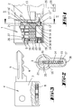
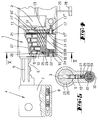
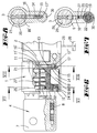
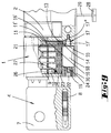
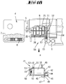
- the profile cylinder according to the invention has a housing 1, in which a closing member 2 is arranged.
- a closing member 2 is arranged.
- it is a double lock cylinder with two opposing cylinder cores 20.
- One of the cores 20 is equipped with an electromagnetically actuated locking pin 14.
- In the cylinder core 20 there are core pins 9 in transverse bores, which are classified by profiles 6 of a key 4.
- the profiles 6 consist of notches in the locking bit 5.
- the housing pins 10 arranged in the housing and aligned with the core pins 9 lie in bores 25.
- the bores are closed by the outer wall of a sleeve 24, which is inserted parallel to the axis of the core 20 in a corresponding opening in the profile section of the profile cylinder.
- the springs 26 are therefore supported on the sleeve wall.
- a total of six pin tumblers are provided, which are in a row.
- the first pin tumbler 9, 10 seen in the direction of insertion actuates a switch for a transmitter.
- the housing pin 10 has a magnet 27 on its end face facing the bottom of the bore 25, which magnet cooperates with a magnetic switch (not shown) arranged in the sleeve.
- the sleeve has an opening 23 through which the magnetic excitation of the magnetic switch can be achieved.
- the last tumbler 11, 12 in the insertion direction of the key 1 is provided with an additional locking pin 14.
- the core pin has a blind hole which is aligned with a through hole in the housing pin 12.
- the additional pin 14 is inserted into the bore made coaxially to the housing pin 12.
- the additional pin 14 has a foot 15 with an enlarged diameter.
- the diameter of the foot 15 corresponds to the diameter of the housing pin 10.
- the diameter of the additional pin 14 is less than the diameter of the pin bore.
- the housing base 15 is spring-loaded relative to the housing pin 10 by means of a spring 13 surrounding the pin 14, so that the pin tumbler 10, 11 is pressed in the core direction.
- the downwardly rounded foot 15 of the pin 14 rests on an armature 17 of an electromagnet 18.
- the armature 17 has a large-diameter area 17 'and a small-diameter area 17' '.
- the areas 17 ', 17' ' are separated from one another by a frustoconical ramp.
- the armature 17 can be displaced in the axial direction by actuating the electromagnet 18.
- the electromagnet 18 is arranged in said sleeve 24.
- an antenna 19 which interacts with a transponder arranged in the cover 7 of the key 8.
- an emergency opening 22 is provided, which can be operated manually or separately electrically in order to actuate the electromagnet or the armature if there is a fault in the electrical control or the batteries are empty.
- a connecting cable 29 projecting approximately centrally from the profile area of the cylinder connects the antenna 19 and the electromagnet 18 with control electronics 39 and a transmitting part 38.
- the cable 29 has a plug 28 at the end.
- the transmitting part 38, the control electronics 39 and a battery compartment 40 are assigned to a separate housing 33, which is arranged below or above the mortise lock 37 behind the cuff in a slot in the door.
- the cuff 31 can be covered with a flap 32.
- the battery compartment 40 can be removed by opening the flap 32.
- a groove 30 is provided in the outer jacket area of the lock cylinder housing 1, into which the cable 29 can be inserted in certain areas.
- the energy is required for the transponder 8 to generate an electromagnetically coded signal sends back to the antenna.
- This signal which is picked up by the antenna 19, is evaluated in the control electronics 39. If this signal is a correct code, the electromagnet 18 is actuated. The anchor 17 is withdrawn.
- the armature 17 In the position shown in Fig. 4, the armature 17 is still in the advanced position.
- the foot 15 of the locking pin 14 rests on the large-diameter section 17 'of the armature 17, so that the end face 16' of the locking end 16 of the locking pin 14 lies above the parting line 21 of the cylinder core 20.
- the locking position shown in FIG. 9 is a key with the correct mechanical coding, but with the wrong electronic coding.
- the signal emitted by the transponder 8 is not the right one.
- the armature 17 does not move back so that the foot 15 of the locking pin 14 rests on the larger diameter region 17 'of the armature 17.
- the locking end 16 projects with the end edge 16 ′ over the parting line 21 into the area of the core 20.
- the locking pin prevents rotation in this position of the locking cylinder.
- the lock cylinder cannot be turned.
- the compartment 33 which can be inserted into a separate opening on the narrow side of the door parallel to the mortise lock opening, is provided with a cover 32.
- the cover 32 runs parallel to the cuff 31 and is hinged to the cuff.
- insertion openings 36 are provided for batteries.
- a display device 34 is also provided, with which the coding or other lock parameters can be represented.
- the electronic closing parameters can be set by means of adjusting buttons 35. With the buttons 35, the coding of the lock can be changed in particular.
- the display 34 assigned to the cuff shows the current or changed locking code.
- FIGS. 13 to 18 functions essentially the same as the aforementioned embodiment. For this reason, the parts that function similarly or identically here are provided with the same reference numbers.
- a carrier 50 is provided, on which the magnet coil 18, the antenna 19, the plunger armature 17 and the feed line 47 are arranged. The whole forms an assembly 41.
- the antenna 19 is arranged in a plastic cap 56 and lies on the end face of the profile locking cylinder or the carrier 50.
- the assembly 41 can be inserted into a radial recess 55 of the profile locking cylinder housing 1.
- the carrier or the electromagnet 18 forms the bottom of the housing bores in which the housing pins 10 are movable and on which support the springs.
- the feed line 47 is guided in the joint between the recess 55 and the adjacent wall of the assembly group 41.
- the feed line is designed as a flexible strip line and extends as far as the antenna 19.
- the carrier 50 which is made of metal, forms pin extensions 49, which can be inserted in corresponding bores in the housing in the radial direction.
- the housing 1 forms a bore running parallel to the housing pin bores, in which an internal thread is cut, in which a fastening screw for the assembly 41 can be screwed.
- the locking cylinder housing 1 has a bore 57 into which a sensor 51 projects.
- the sensor 51 is connected to a flag of the feed line via contacts 53.
- the sensor is located below the housing pin, so that the housing pin is outside the sensor area when the key is not inserted.
- the sensor 51 is a magnetically activatable sensor which interacts with the magnetic first housing pin 52 as soon as a key is inserted and the pin 52 is moved downward into the sensor area.
- the plunger armature 17 emerging axially from the electromagnet 18 has a longitudinal groove 44 on its lower side. A projection of a stopper 45 engages in this longitudinal groove.
- the plunger anchor 17 is non-rotatably mounted.
- the flattened area 42 of the submersible anchor 17 can therefore have a sufficiently large spacing from the flattened area 43, which merges into the flat area 42 via an inclined step.
- the plug 45 is inserted into an opening of the carrier 50 and leaves a gap 48 between it and an adjacent projection 46, through which the feed line emerges.
- the projection 46 lies on the longitudinal narrow side of the profile locking cylinder and thus forms a pull guard.
- the projection 46 is supported to develop its protective effect against a fitting plate screwed on from the outside.
- the assembly 41 supplements the recess 55 to form a profile cylinder, in particular the longitudinal narrow side of the flange section is formed by the carrier 50. Because the carrier 50 can be inserted in the radial direction into the flange area of the locking cylinder, removal from the locking cylinder housing 1 is only possible when the locking cylinder has been removed.
- the assembly of all components relating to the additional electromagnetic locking device in one assembly simplifies assembly. It is particularly advantageous if the plug 45 closes an opening which is arranged in alignment with the electromagnetically actuated locking pin 14.
Landscapes
- Physics & Mathematics (AREA)
- Electromagnetism (AREA)
- Lock And Its Accessories (AREA)
- Mechanical Control Devices (AREA)
- Turbine Rotor Nozzle Sealing (AREA)
Priority Applications (1)
| Application Number | Priority Date | Filing Date | Title |
|---|---|---|---|
| EP98115682A EP0882858B1 (fr) | 1994-10-25 | 1995-10-24 | Serrure cylindrique à goupille électromagnétique |
Applications Claiming Priority (4)
| Application Number | Priority Date | Filing Date | Title |
|---|---|---|---|
| DE4437997 | 1994-10-25 | ||
| DE4437997 | 1994-10-25 | ||
| DE19539235 | 1995-10-21 | ||
| DE19539235A DE19539235A1 (de) | 1994-10-25 | 1995-10-21 | Schließzylinder mit elektromagnetisch betätigbarem Sperrstift |
Related Child Applications (1)
| Application Number | Title | Priority Date | Filing Date |
|---|---|---|---|
| EP98115682A Division EP0882858B1 (fr) | 1994-10-25 | 1995-10-24 | Serrure cylindrique à goupille électromagnétique |
Publications (3)
| Publication Number | Publication Date |
|---|---|
| EP0709533A2 true EP0709533A2 (fr) | 1996-05-01 |
| EP0709533A3 EP0709533A3 (fr) | 1996-09-04 |
| EP0709533B1 EP0709533B1 (fr) | 1999-04-21 |
Family
ID=25941329
Family Applications (1)
| Application Number | Title | Priority Date | Filing Date |
|---|---|---|---|
| EP95116755A Expired - Lifetime EP0709533B1 (fr) | 1994-10-25 | 1995-10-24 | Serrure cylindrique à goupille électromagnétique |
Country Status (3)
| Country | Link |
|---|---|
| EP (1) | EP0709533B1 (fr) |
| AT (2) | ATE209288T1 (fr) |
| ES (2) | ES2164399T3 (fr) |
Cited By (7)
| Publication number | Priority date | Publication date | Assignee | Title |
|---|---|---|---|---|
| NL1004691C2 (nl) * | 1996-12-04 | 1998-06-08 | Hubertus Joseph Hendricus Mari | Cilinderslot met bedienbare vergrendeling. |
| EP1980693A3 (fr) * | 2007-04-12 | 2008-10-22 | ASSA ABLOY Sicherheitstechnik GmbH | Cylindre de serrure |
| DE10329414B4 (de) * | 2003-07-01 | 2012-02-02 | Cestronics Gmbh | Schließvorrichtung |
| WO2014096442A3 (fr) * | 2012-12-23 | 2014-08-28 | Certaflex Bv | Serrure à cylindre et combinaison d'une telle serrure et d'une clé |
| SE2050450A1 (en) * | 2020-04-21 | 2021-10-22 | Assa Abloy Ab | Bumping preventing arrangement for lock device, lock device and method |
| CN114650726A (zh) * | 2022-05-12 | 2022-06-21 | 航天亮丽电气有限责任公司 | 一种多引脚自动矫正插件机构 |
| EP4336001A1 (fr) * | 2022-09-07 | 2024-03-13 | Aug. Winkhaus GmbH & Co. KG | Cylindre de fermeture |
Citations (1)
| Publication number | Priority date | Publication date | Assignee | Title |
|---|---|---|---|---|
| DE4126160A1 (de) | 1991-08-07 | 1993-02-11 | Winkhaus Fa August | Schliesszylinder, insbesondere fuer einsteckschloesser |
Family Cites Families (8)
| Publication number | Priority date | Publication date | Assignee | Title |
|---|---|---|---|---|
| US3670538A (en) * | 1970-11-12 | 1972-06-20 | Robert E Curry | Controllable key lock |
| US4068507A (en) * | 1976-08-11 | 1978-01-17 | C. Hager & Sons Hinge Manufacturing Company | Limited access lock |
| GB2055951B (en) * | 1980-08-04 | 1983-03-16 | Day H V | Locks |
| CH671800A5 (fr) * | 1987-02-09 | 1989-09-29 | Berchtold Ag | |
| DE3800414A1 (de) * | 1988-01-09 | 1989-07-20 | Bks Gmbh | Schliesszylinder, insbesondere fuer einsteckschloesser bestimmter profilzylinder |
| GB2219031B (en) * | 1988-05-19 | 1992-07-22 | Yale Security Prod Ltd | Lock including electrical release means |
| AT394604B (de) * | 1990-04-10 | 1992-05-25 | Grundmann Gmbh Geb | Schliesszylinder mit eingebauter, elektromechanischer sperre |
| DE9217524U1 (de) * | 1992-12-22 | 1993-04-15 | Ikon AG Präzisionstechnik, 1000 Berlin | Doppelschließzylinder |
-
1995
- 1995-10-24 ES ES98115682T patent/ES2164399T3/es not_active Expired - Lifetime
- 1995-10-24 ES ES95116755T patent/ES2130494T3/es not_active Expired - Lifetime
- 1995-10-24 AT AT98115682T patent/ATE209288T1/de not_active IP Right Cessation
- 1995-10-24 EP EP95116755A patent/EP0709533B1/fr not_active Expired - Lifetime
- 1995-10-24 AT AT95116755T patent/ATE179236T1/de not_active IP Right Cessation
Patent Citations (1)
| Publication number | Priority date | Publication date | Assignee | Title |
|---|---|---|---|---|
| DE4126160A1 (de) | 1991-08-07 | 1993-02-11 | Winkhaus Fa August | Schliesszylinder, insbesondere fuer einsteckschloesser |
Cited By (11)
| Publication number | Priority date | Publication date | Assignee | Title |
|---|---|---|---|---|
| NL1004691C2 (nl) * | 1996-12-04 | 1998-06-08 | Hubertus Joseph Hendricus Mari | Cilinderslot met bedienbare vergrendeling. |
| DE10329414B4 (de) * | 2003-07-01 | 2012-02-02 | Cestronics Gmbh | Schließvorrichtung |
| EP1980693A3 (fr) * | 2007-04-12 | 2008-10-22 | ASSA ABLOY Sicherheitstechnik GmbH | Cylindre de serrure |
| WO2014096442A3 (fr) * | 2012-12-23 | 2014-08-28 | Certaflex Bv | Serrure à cylindre et combinaison d'une telle serrure et d'une clé |
| US10066419B2 (en) | 2012-12-23 | 2018-09-04 | Almotec B.V. | Cylinder lock and combination of such a lock and key |
| SE2050450A1 (en) * | 2020-04-21 | 2021-10-22 | Assa Abloy Ab | Bumping preventing arrangement for lock device, lock device and method |
| WO2021214036A1 (fr) * | 2020-04-21 | 2021-10-28 | Assa Abloy Ab | Agencement de prévention de bossage destiné à un dispositif de verrouillage, dispositif de verrouillage et procédé |
| SE544071C2 (en) * | 2020-04-21 | 2021-12-07 | Assa Abloy Ab | Bumping preventing arrangement for lock device, lock device and method |
| US12338654B2 (en) | 2020-04-21 | 2025-06-24 | Assa Abloy Ab | Bumping preventing arrangement for lock device, lock device and method |
| CN114650726A (zh) * | 2022-05-12 | 2022-06-21 | 航天亮丽电气有限责任公司 | 一种多引脚自动矫正插件机构 |
| EP4336001A1 (fr) * | 2022-09-07 | 2024-03-13 | Aug. Winkhaus GmbH & Co. KG | Cylindre de fermeture |
Also Published As
| Publication number | Publication date |
|---|---|
| EP0709533A3 (fr) | 1996-09-04 |
| ES2130494T3 (es) | 1999-07-01 |
| ATE209288T1 (de) | 2001-12-15 |
| ATE179236T1 (de) | 1999-05-15 |
| EP0709533B1 (fr) | 1999-04-21 |
| ES2164399T3 (es) | 2002-02-16 |
Similar Documents
| Publication | Publication Date | Title |
|---|---|---|
| EP1636454B1 (fr) | Barillet electromagnetique | |
| DE3880496T2 (de) | Von einer batterie betriebenes tuerschloss sowie verfahren. | |
| EP0324096B1 (fr) | Serrure à cylindre, notamment cylindre pour serrure encastrée | |
| EP0995864B1 (fr) | Système de verrouillage électromécanique | |
| DE19520211A1 (de) | Elektronische Verriegelungsanordnung für ein Schloßsystem | |
| DE60115075T2 (de) | Elektromechanisches zylinderschloss und schlüssel | |
| EP0368018B1 (fr) | Serrure pour porte | |
| WO1988005853A1 (fr) | Dispositif de fermeture electromecanique | |
| DE19930054C5 (de) | Elektromechanisches Schließsystem | |
| DE3632904A1 (de) | Schliesseinrichtung fuer ein mechanisch/elektronisches schliess-system | |
| EP0882858B1 (fr) | Serrure cylindrique à goupille électromagnétique | |
| EP0140028B1 (fr) | Installation de fermeture de sécurité avec un dispositif d'accouplement à deux axes, aimant d'arrêt, entraîneur et montage de réserve | |
| DE19604442A1 (de) | Sicherheitsvorrichtung für elektronische Schlösser | |
| EP0709533B1 (fr) | Serrure cylindrique à goupille électromagnétique | |
| EP0428892B1 (fr) | Serrure cylindrique double | |
| DE10324690A1 (de) | Ferngesteuert freigebbarer Schließzylinder | |
| DE19923786A1 (de) | Schließzylinder | |
| EP1174572B1 (fr) | Serrure cylindrique disposant d'un agencement pour la transmission de signal sans contact | |
| EP0173987B1 (fr) | Serrure complémentaire pour portes avec système de fermeture de sécurité | |
| DE3521822A1 (de) | Sender- und empfaengergesteuerte schliesseinrichtung | |
| EP1323880A2 (fr) | Serrure cylindrique, notamment pour serrure encastrée | |
| DE102021114239A1 (de) | Schlüssel mit einer Schlüsselreide und mit einem Schlüsselschaft und einem Generator | |
| EP3412851B1 (fr) | Dispositif de fouillot de loquet pour une serrure | |
| DE19602438A1 (de) | Kombinationsschloß | |
| DE4314903A1 (de) | Schloßanordnung |
Legal Events
| Date | Code | Title | Description |
|---|---|---|---|
| PUAI | Public reference made under article 153(3) epc to a published international application that has entered the european phase |
Free format text: ORIGINAL CODE: 0009012 |
|
| AK | Designated contracting states |
Kind code of ref document: A2 Designated state(s): AT BE CH DE ES FR GB IT LI LU NL |
|
| PUAL | Search report despatched |
Free format text: ORIGINAL CODE: 0009013 |
|
| AK | Designated contracting states |
Kind code of ref document: A3 Designated state(s): AT BE CH DE ES FR GB IT LI LU NL |
|
| 17P | Request for examination filed |
Effective date: 19970227 |
|
| 17Q | First examination report despatched |
Effective date: 19980205 |
|
| GRAG | Despatch of communication of intention to grant |
Free format text: ORIGINAL CODE: EPIDOS AGRA |
|
| GRAG | Despatch of communication of intention to grant |
Free format text: ORIGINAL CODE: EPIDOS AGRA |
|
| GRAH | Despatch of communication of intention to grant a patent |
Free format text: ORIGINAL CODE: EPIDOS IGRA |
|
| GRAH | Despatch of communication of intention to grant a patent |
Free format text: ORIGINAL CODE: EPIDOS IGRA |
|
| GRAA | (expected) grant |
Free format text: ORIGINAL CODE: 0009210 |
|
| AK | Designated contracting states |
Kind code of ref document: B1 Designated state(s): AT BE CH DE ES FR GB IT LI LU NL |
|
| REF | Corresponds to: |
Ref document number: 179236 Country of ref document: AT Date of ref document: 19990515 Kind code of ref document: T |
|
| REG | Reference to a national code |
Ref country code: CH Ref legal event code: NV Representative=s name: R. A. EGLI & CO. PATENTANWAELTE Ref country code: CH Ref legal event code: EP |
|
| GBT | Gb: translation of ep patent filed (gb section 77(6)(a)/1977) |
Effective date: 19990421 |
|
| REF | Corresponds to: |
Ref document number: 59505700 Country of ref document: DE Date of ref document: 19990527 |
|
| ET | Fr: translation filed | ||
| REG | Reference to a national code |
Ref country code: ES Ref legal event code: FG2A Ref document number: 2130494 Country of ref document: ES Kind code of ref document: T3 |
|
| PLBE | No opposition filed within time limit |
Free format text: ORIGINAL CODE: 0009261 |
|
| STAA | Information on the status of an ep patent application or granted ep patent |
Free format text: STATUS: NO OPPOSITION FILED WITHIN TIME LIMIT |
|
| 26N | No opposition filed | ||
| PGFP | Annual fee paid to national office [announced via postgrant information from national office to epo] |
Ref country code: BE Payment date: 20010912 Year of fee payment: 7 Ref country code: AT Payment date: 20010912 Year of fee payment: 7 |
|
| PGFP | Annual fee paid to national office [announced via postgrant information from national office to epo] |
Ref country code: CH Payment date: 20010913 Year of fee payment: 7 |
|
| PGFP | Annual fee paid to national office [announced via postgrant information from national office to epo] |
Ref country code: LU Payment date: 20011023 Year of fee payment: 7 |
|
| REG | Reference to a national code |
Ref country code: GB Ref legal event code: IF02 |
|
| PG25 | Lapsed in a contracting state [announced via postgrant information from national office to epo] |
Ref country code: LU Free format text: LAPSE BECAUSE OF NON-PAYMENT OF DUE FEES Effective date: 20021024 Ref country code: AT Free format text: LAPSE BECAUSE OF NON-PAYMENT OF DUE FEES Effective date: 20021024 |
|
| PG25 | Lapsed in a contracting state [announced via postgrant information from national office to epo] |
Ref country code: LI Free format text: LAPSE BECAUSE OF NON-PAYMENT OF DUE FEES Effective date: 20021031 Ref country code: CH Free format text: LAPSE BECAUSE OF NON-PAYMENT OF DUE FEES Effective date: 20021031 Ref country code: BE Free format text: LAPSE BECAUSE OF NON-PAYMENT OF DUE FEES Effective date: 20021031 |
|
| PGFP | Annual fee paid to national office [announced via postgrant information from national office to epo] |
Ref country code: FR Payment date: 20021112 Year of fee payment: 8 |
|
| PGFP | Annual fee paid to national office [announced via postgrant information from national office to epo] |
Ref country code: ES Payment date: 20021113 Year of fee payment: 8 |
|
| PGFP | Annual fee paid to national office [announced via postgrant information from national office to epo] |
Ref country code: GB Payment date: 20021114 Year of fee payment: 8 |
|
| BERE | Be: lapsed |
Owner name: *ANKERSLOT B.V. Effective date: 20021031 Owner name: *WILKA SCHLIESSTECHNIK G.M.B.H. Effective date: 20021031 |
|
| REG | Reference to a national code |
Ref country code: CH Ref legal event code: PL |
|
| PG25 | Lapsed in a contracting state [announced via postgrant information from national office to epo] |
Ref country code: GB Free format text: LAPSE BECAUSE OF NON-PAYMENT OF DUE FEES Effective date: 20031024 |
|
| PG25 | Lapsed in a contracting state [announced via postgrant information from national office to epo] |
Ref country code: ES Free format text: LAPSE BECAUSE OF NON-PAYMENT OF DUE FEES Effective date: 20031025 |
|
| GBPC | Gb: european patent ceased through non-payment of renewal fee |
Effective date: 20031024 |
|
| PG25 | Lapsed in a contracting state [announced via postgrant information from national office to epo] |
Ref country code: FR Free format text: LAPSE BECAUSE OF NON-PAYMENT OF DUE FEES Effective date: 20040630 |
|
| REG | Reference to a national code |
Ref country code: FR Ref legal event code: ST |
|
| REG | Reference to a national code |
Ref country code: ES Ref legal event code: FD2A Effective date: 20031025 |
|
| PG25 | Lapsed in a contracting state [announced via postgrant information from national office to epo] |
Ref country code: IT Free format text: LAPSE BECAUSE OF NON-PAYMENT OF DUE FEES Effective date: 20051024 |
|
| PGFP | Annual fee paid to national office [announced via postgrant information from national office to epo] |
Ref country code: NL Payment date: 20071015 Year of fee payment: 13 Ref country code: DE Payment date: 20071012 Year of fee payment: 13 |
|
| NLV4 | Nl: lapsed or anulled due to non-payment of the annual fee |
Effective date: 20090501 |
|
| PG25 | Lapsed in a contracting state [announced via postgrant information from national office to epo] |
Ref country code: NL Free format text: LAPSE BECAUSE OF NON-PAYMENT OF DUE FEES Effective date: 20090501 |
|
| PG25 | Lapsed in a contracting state [announced via postgrant information from national office to epo] |
Ref country code: DE Free format text: LAPSE BECAUSE OF NON-PAYMENT OF DUE FEES Effective date: 20090501 |