EP0709619B1 - Kfz-Scheinwerfer mit Mehrflächen-Reflektor - Google Patents
Kfz-Scheinwerfer mit Mehrflächen-Reflektor Download PDFInfo
- Publication number
- EP0709619B1 EP0709619B1 EP95116738A EP95116738A EP0709619B1 EP 0709619 B1 EP0709619 B1 EP 0709619B1 EP 95116738 A EP95116738 A EP 95116738A EP 95116738 A EP95116738 A EP 95116738A EP 0709619 B1 EP0709619 B1 EP 0709619B1
- Authority
- EP
- European Patent Office
- Prior art keywords
- headlight
- optical axis
- ellipse
- sectors
- reflector
- Prior art date
- Legal status (The legal status is an assumption and is not a legal conclusion. Google has not performed a legal analysis and makes no representation as to the accuracy of the status listed.)
- Expired - Lifetime
Links
- 230000003287 optical effect Effects 0.000 claims description 39
- 230000004313 glare Effects 0.000 claims description 4
- 238000011960 computer-aided design Methods 0.000 description 5
- 238000010276 construction Methods 0.000 description 5
- 238000004519 manufacturing process Methods 0.000 description 5
- 238000000034 method Methods 0.000 description 4
- 238000012360 testing method Methods 0.000 description 4
- 230000000694 effects Effects 0.000 description 2
- 230000004075 alteration Effects 0.000 description 1
- 230000004323 axial length Effects 0.000 description 1
- 230000015572 biosynthetic process Effects 0.000 description 1
- 238000004364 calculation method Methods 0.000 description 1
- 239000012141 concentrate Substances 0.000 description 1
- 238000013461 design Methods 0.000 description 1
- 238000010438 heat treatment Methods 0.000 description 1
- 238000002347 injection Methods 0.000 description 1
- 239000007924 injection Substances 0.000 description 1
- 239000000463 material Substances 0.000 description 1
- 239000002184 metal Substances 0.000 description 1
- 230000002093 peripheral effect Effects 0.000 description 1
- 239000000243 solution Substances 0.000 description 1
- 238000013519 translation Methods 0.000 description 1
Images



Classifications
-
- F—MECHANICAL ENGINEERING; LIGHTING; HEATING; WEAPONS; BLASTING
- F21—LIGHTING
- F21S—NON-PORTABLE LIGHTING DEVICES; SYSTEMS THEREOF; VEHICLE LIGHTING DEVICES SPECIALLY ADAPTED FOR VEHICLE EXTERIORS
- F21S41/00—Illuminating devices specially adapted for vehicle exteriors, e.g. headlamps
- F21S41/30—Illuminating devices specially adapted for vehicle exteriors, e.g. headlamps characterised by reflectors
- F21S41/32—Optical layout thereof
- F21S41/33—Multi-surface reflectors, e.g. reflectors with facets or reflectors with portions of different curvature
- F21S41/334—Multi-surface reflectors, e.g. reflectors with facets or reflectors with portions of different curvature the reflector consisting of patch like sectors
- F21S41/336—Multi-surface reflectors, e.g. reflectors with facets or reflectors with portions of different curvature the reflector consisting of patch like sectors with discontinuity at the junction between adjacent areas
-
- F—MECHANICAL ENGINEERING; LIGHTING; HEATING; WEAPONS; BLASTING
- F21—LIGHTING
- F21S—NON-PORTABLE LIGHTING DEVICES; SYSTEMS THEREOF; VEHICLE LIGHTING DEVICES SPECIALLY ADAPTED FOR VEHICLE EXTERIORS
- F21S41/00—Illuminating devices specially adapted for vehicle exteriors, e.g. headlamps
- F21S41/30—Illuminating devices specially adapted for vehicle exteriors, e.g. headlamps characterised by reflectors
- F21S41/32—Optical layout thereof
- F21S41/33—Multi-surface reflectors, e.g. reflectors with facets or reflectors with portions of different curvature
- F21S41/334—Multi-surface reflectors, e.g. reflectors with facets or reflectors with portions of different curvature the reflector consisting of patch like sectors
- F21S41/335—Multi-surface reflectors, e.g. reflectors with facets or reflectors with portions of different curvature the reflector consisting of patch like sectors with continuity at the junction between adjacent areas
Definitions
- the present invention relates to a road vehicle headlight, in particular a lower beam, featuring a complex-surface reflector in conjunction with a prism optical system.
- French Patent n. 2.536.502 relates to a road vehicle lower beam headlight comprising a body housing a reflector and a light source, and a prism lens in front of the reflector and closing the body.
- the reflector is defined by a complex surface formed by the continuous connection of various types of reflecting surfaces defined by various equations. More specifically, the complex surface described in French Patent n.
- 2.536.502 comprises two parabolic surface portions arranged at the regulation cutoff line angle; and two portions of a surface not of revolution, described by a mathematical equation and which, on the one hand, connects the two parabolic portions and, on the other, in conjunction with the lens prisms of the light, provides for collecting and distributing the source-emitted beam over 360° about the source.
- the lower beam light according to French Patent n. 2.536.502 provides for exploiting all the light emitted by the source, thus enabling the use of low-power lamps (and so reducing consumption and heating) or smaller reflectors for a given brightness of the beam.
- it fails to provide for optimum distribution of the beam.
- German Patent n. DE-B-3341773 which represents the German counterpart of French Patent n.
- a vehicle headlight for generating a lower or fog light beam concentrated entirely beneath the cutoff line for preventing glare;
- the headlight comprising a light source and a reflector, and being of the type wherein the reflector collects the source-emitted light over 360° about the source;
- the reflector presents a complex reflecting surface comprising four sectors, a first pair of which is located on one side of the optical axis, and a second pair of which is located on the opposite side; the surfaces of the sectors in each pair being connected to each other continuously at respective half planes extending through the optical axis and arranged according to the cutoff line; said surfaces being defined in section, at each half plane, by a respective branch of an ellipse, and being defined, over at least 75% of their angular extension, measured from said half planes towards the vertical plane, by the envelope of arcs having centers aligned with said half planes, and offset on either side of the optical axis.
- the light source is preferably off-centered axially in relation to the focal point of the headlight, which is defined by a first focal point common to both said ellipse branches and located along the optical axis, close to the reflector; a second focal point of each ellipse branch being located roughly 25 m from the reflector. More specifically, the light source is defined by a single filament substantially aligned with but slightly above the optical axis, and with its lower side coincident with the optical axis.
- the present invention therefore provides for producing headlights wherein the surfaces of the reflector sectors are defined over 100% of their angular extension by said arcs, and wherein, at the vertical plane, the reflector presents a step at the connection of the sectors below the half planes and at the connection of the sectors above the half planes; which discontinuity, however, in no way impairs performance of the headlight by virtue of the distorted rays being projected well below the cutoff line.
- the present invention also provides for producing headlights with an entirely smooth reflector - which is easier to mold - wherein the remaining 25% of the angular extension of the sector surfaces is formed by connecting curves between the arcs defining the adjacent sectors above and below the half planes.
- the distorted images obviously generated by said 25% of the sector surfaces are well below the cutoff line and, despite contributing light, therefore have practically no effect on the definition of the beam.
- the axes of said two ellipse branches preferably do not coincide with the optical axis of the headlight, but extend through it at said first focal point common to both branches and, in the respective half planes, are oppositely inclined in relation to the common focal point by an angle ranging between 0.5° and 2°, so that the second focal points of the two ellipse branches are separated by a predetermined distance perpendicular to the optical axis.
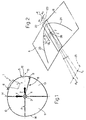
- number 1 indicates a headlight for generating a lower or a fog light beam which, as is known, must be concentrated entirely below a cutoff line 2 ( Figure 3) to avoid dazzling motorists traveling in the opposite direction.
- a cutoff line 2 Figure 3
- the non-limiting example described shows a European cutoff line 2 for lower beam headlights, defined by two lines 2a, 2b, the second inclined at 15° in relation to the first.
- Headlight 1 comprises a light source 3 consisting of a spiral filament of an incandescent lamp, parallel to the optical axis 4 of headlight 1; a reflector 5; a casing 6 housing reflector 5 and source 3; and a prism lens 7 opposite reflector 5 and closing casing 6.
- cutoff line 2 is defined by the particular light distribution effected by reflector 5, the reflecting surface 8 of which, facing lens 7, collects the source-emitted light over all 360° about source 3 and projects all the reflected images of filament 3 below cutoff line 2.
- reflecting surface 8 is a complex surface, i.e. comprising a number of sectors defined by surfaces (reflecting or deflecting) with different optical characteristics as compared with those of the adjacent sector surfaces.
- surface 8 comprises four sectors 10, 11, 12, 13.
- sectors 10 and 11 are arranged one over the other, on one side of optical axis 4 and to the left of a vertical plane 14 through axis 4; and sectors 12 and 13 are arranged one over the other on the opposite side, i.e. to the right of plane 14.
- sectors 12 and 13 are defined by respective reflecting surfaces which are connected continuously at a half plane B also through axis 4 and at an angle to half plane A.
- half planes A and B present the same configuration as the required cutoff line 2, so that, in the case of the lower beam described, half plane B forms and angle of fifteen degrees in relation to half plane A.
- the following description obviously also applies to headlights with a cutoff line of any other configuration; and, though reflector 5 in the non-limiting example shown presents a curved peripheral edge 16, the following description obviously also applies to headlights featuring reflectors 5 of any shape and contour.
- the surfaces of sectors 10 and 11 are defined in section, at half plane A, by an ellipse branch 20 common to both surfaces; and the surfaces of sectors 12 and 13 are defined in section, at half plane B, by a respective ellipse branch 21 also common to both surfaces.
- the reflector according to the present invention is cut along the two half planes A and B, the contour of the section will correspond geometrically to ellipse branches 20 and 21.
- ellipses 20 and 21 are defined by a first, common, focal point F close to reflector 5, e.g. roughly 25 mm from surface 8, and by a second focal point, indicated F1 for ellipse 20 and F2 for ellipse 21, located roughly 25 m from surface 8, i.e. substantially at a standard regulation vehicle headlight test screen.
- the respective axes 22 and 23 of branches 20 and 21 do not coincide with optical axis 4 but intersect it at common focal point F, and, in respective half planes A and B, are oppositely inclined in relation to axis 4 by respective angles ⁇ 1 and ⁇ 2 generally equal to each other and at any rate ranging between 0.5° and 2°.
- the common focal point F of ellipses 20 and 21 is assumed as the (virtual) focal point of headlight 1, and the source defined by filament 3 is off-centered axially in relation to focal point F. More specifically (Figure 2), filament 3, which presents a length Lf, is substantially aligned parallel to but slightly above optical axis 4, with its axis offset radially by a distance equal to half its diameter, so that its lower side 26 is coincident with optical axis 4, as previously claimed and described in the U.K. patent Application No. 25310/76 (DE-A-2 726 951) in the name of LUCAS Ind..
- the above location values of source 3 in relation to axis 4 and focal point F must be respected accurately, when assembling headlight 1, within a maximum tolerance of 5% of length Lf.
- the surfaces of sectors 10, 11 and 12, 13 are defined, over at least 75% of their angular extension measured from half planes A and B towards vertical plane 14, by the envelope of arcs all having their centers in a plane aligned coplanar with one of half planes A and B, and offset by a predetermined amount on either side of optical axis 4.
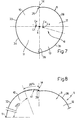
- the centers C 1 and C 4 ( Figure 7) of the arcs whose envelope defines the surfaces of diagonally-opposed sectors 10 and 13 respectively above and below half planes A and B, as well as the centers C 2 and C 3 ( Figure 7) of the arcs whose envelope defines the surfaces of sectors 11 and 12 opposite sectors 10 and 13, are located at a distance from optical axis 4, measured parallel to respective half plane A or B, equal to the geometric difference (in modulus and sign) of the coordinates of the points of respective ellipse branch 20 or 21 defined at respective half plane A or B, and the location of the corresponding points of a respective (fictitious) ellipse branch 30 ( Figure 4) or 31 ( Figure 6) located in vertical plane 14 respectively above and below optical axis 4, and so located as to be respectively converging or diverging in relation to the location of focal point F.
- a first possible embodiment of reflector 5 for a headlight 1 presents, at vertical plane 14, steps 35 and 36 respectively connecting adjacent upper sectors 10, 12, and corresponding lower sectors 11, 13; in which case, the surfaces of sectors 10, 11 and 12, 13 are defined over 100% of their angular extension by said arcs.
- steps 35 and 36 are formed as a result of the "construction" method adopted for the surfaces of reflector 5, do not constitute a serious drawback from the construction standpoint, and, according to the present invention, in no way constitute an optical drawback in that, by virtue of the steps being aligned coplanar with the fictitious ellipses 30 and 31 used, as will be seen, for forming surface 8, the images projected by them are located at the lower limit of the images projected by reflector 5.
- the surfaces of adjacent sectors 10, 12 and 11, 13 are connected continuously also at vertical plane 14, so that steps 35 and 36 are absent.
- this is achieved by the arc envelope forming only roughly 75% of the angular extension of the surfaces of the adjacent sectors, the remaining roughly 25% of the surface of sectors 10 and 11 being formed by the envelope of specific curves (one of which is indicated as 41 in Figure 8) connecting the arcs at the same location along optical axis 4, to define the adjacent sectors above and below half planes A and B, i.e. by the envelope of the curves respectively connecting the adjacent portions of sectors 10, 12 and 11, 13.
- the method for obtaining the surfaces forming the sectors of reflector 5 is based on preliminary computer-aided design (CAD) and, successively, on transferring the designs, complete with all the dimensions calculated point by point, directly to chip-forming production machines (CIM) for producing dies of suitable material with which reflector 5 is injection molded from plastic (or drawn from sheet metal) in conventional manner.
- CAD computer-aided design
- CIM chip-forming production machines
- the first step in the formation of surface 8 of reflector 5 comprises arbitrarily establishing an optical axis and a focal point along the optical axis about which to construct "in reverse" the required surface.
- the fictitious optical axis selected is axis 4 which is the one extending along the lower edge 26 of the filament of the light source 3 used, e.g. an incandescent lamp of given power; and the fictitious focal point F selected is a point along axis 4, located roughly 1/4 ( ⁇ 5%) of the way along the length Lf of the filament, as of the end facing reflector 5.
- two ellipses 20 and 21 are drawn in half planes A and B, with the first, common, focal point at F and the second focal point at a distance of 25 m.
- Ellipses 20 and 21 are preferably so drawn as to present noncoincident axes 22 and 23 inclined slightly in relation to axis 4.
- ellipses 20 and 21 which may be expressed by an equation defining the single points of the ellipses within the three-dimensional Y, Z, X reference system, wherein optical axis 4 is selected as the X axis ( Figures 4, 5 and 6).
- optical axis 4 is selected as the X axis ( Figures 4, 5 and 6).
- a further two ellipses 30 and 31 are defined in vertical plane 14, but which, unlike ellipses 20 and 21, do not actually form part of surface 8 and are merely a fictitious mathematical construction for calculation purposes.
- ellipses 30 and 31 are defined with the second focal point (the one furthest away from reflector 5) at a distance of 25 m along axis 4, i.e.
- Fd is the location along axis 4 of the diverging focal point from point F, i.e. the first focal point of ellipse 31;
- Fl is the axial length of filament 3;
- FT is the maximum fabrication tolerance of filament 3; and
- C is a constant expressed as a percentage and depending on the fabrication tolerances of reflector 5.
- each sector 10, 11, 12, 13 is defined mathematically.
- Circumference 33 is drawn from half plane A, i.e. from the point of ellipse 20 at coordinate Y1n, to the vertical plane, i.e. over an arc greater than 90°, in that, in relation to axis 4 at which the Xn coordinates are measured, C1n is offset laterally by quantity Yn which in this case, calculating the algebraic sum, is negative (i.e. shifted to the left of axis 4 looking towards reflector 5) and represents the eccentricity of circumference 33 in relation to axis 4.
- Sector 12 is constructed in the same way - and is therefore not described for the sake of simplicity - except that, in this case, the geometric difference is calculated between values Y2n of ellipse 21 and Y4n of ellipse 30 to give positive offsets and a number of circumferences 36 (Figure 7).
- the surfaces of sectors 10, 12 and 11, 13 are blended at the vertical plane by making a slight adjustment to the algorithms described above.
- This consists in so setting the CAD system that only 75% of the angular extension of each sector 10, 11, 12, 13, or of at least two of these sectors, opposite to each other (the 75% is calculated from respective half plane A or B) is defined by the envelope of the various circumferences of radius Rn and center Cn, the remaining 25% of each surface being defined by the envelope of individual connecting lines 41 draftable for each Xn coordinate for respectively connecting circumferences 33, 36 ( Figure 8) and 34, 35 (not shown in Figure 8 for the sake of simplicity).
- Said curves are calculated in known manner using any type of approximation algorithm.
- Figure 9 shows the curves relative to sector 10, Figure 10 those of sector 12, Figure 11 those of sector 11, and Figure 12 those of sector 13.
- the alteration to the original optical system produced by substituting connecting curves for part of circumferences 33, 34, 35, 36 in no way impairs lighting performance according to the present invention, in that, by virtue of the manner in which the surfaces are formed, the images distorted by the connecting portions are all reflected well below cutoff line 2.
Landscapes
- Engineering & Computer Science (AREA)
- General Engineering & Computer Science (AREA)
- Non-Portable Lighting Devices Or Systems Thereof (AREA)
Claims (7)
- Fahrzeugscheinwerfer zum Erzeugen eines Lichtstrahls, z. B. eines Abblendlichtstrahls, der vollständig unterhalb einer Abschlußlinie konzentriert ist, um ein Blenden zu verhindern; wobei der Scheinwerfer eine Lichtquelle und einen Reflektor enthält und von dem Typ ist, bei dem der Reflektor das von der Quelle ausgesendete Licht über 360° um die Quelle sammelt; dadurch gekennzeichnet, daß der Reflektor eine komplexe Reflexionsoberfläche aufweist, die vier Sektoren enthält, wovon sich ein erstes Paar auf einer Seite der optischen Achse befindet und ein zweites Paar auf der gegenüberliegenden Seite befindet; wobei die Oberflächen der Sektoren jedes Paars an entsprechenden Halbebenen, die durch die optische Achse verlaufen und entsprechend der Kappungslinie angeordnet sind, kontinuierlich miteinander verbunden sind; wobei die Oberflächen im Schnitt in jeder Halbebene durch einen entsprechenden Abschnitt einer Ellipse definiert sind und über wenigstens 75 % ihrer Winkelerstreckung, die von den Halbebenen zur vertikalen Ebene gemessen wird, durch die Einhüllende der Bögen, deren Zentren auf die Halbebenen ausgerichtet sind und beiderseits der optischen Achse versetzt sind, definiert sind.
- Scheinwerfer nach Anspruch 1, dadurch gekennzeichnet, daß die Lichtquelle in bezug auf den Brennpunkt des Scheinwerfers, der durch einen ersten Brennpunkt, der beiden Ellipsenabschnitten gemeinsam ist und sich auf der optischen Achse in der Nähe des Reflektors befindet, definiert ist, vom Zentrum axial versetzt ist; wobei sich der zweite Brennpunkt jedes Ellipsenabschnittes ungefähr 25 m vom Reflektor entfernt befindet.
- Scheinwerfer nach Anspruch 2, dadurch gekennzeichnet, daß die Achsen der beiden Ellipsenabschnitte nicht mit der optischen Achse des Scheinwerfers zusammenfallen, sondern an dem ersten gemeinsamen Brennpunkt der beiden Ellipsenabschnitte durch diese verlaufen und in den entsprechenden Halbebenen in bezug auf die optische Achse um einen Winkel im Bereich von 0,5° bis 2° entgegengesetzt geneigt sind, so daß die zweiten Brennpunkte der beiden Ellipsenabschnitte senkrecht zur optischen Achse um eine vorgegebene Strecke voneinander getrennt sind.
- Scheinwerfer nach Anspruch 2 oder 3, dadurch gekennzeichnet, daß die Lichtquelle durch einen einzigen Glühfaden definiert ist, der im wesentlichen auf die optische Achse ausgerichtet ist, sich jedoch leicht oberhalb dieser befindet, wobei seine Unterseite mit der optischen Achse zusammenfällt; und ungefähr 25 % der Länge des Glühfadens hinter dem Brennpunkt des Scheinwerfers in Richtung zum Reflektor verlaufen, während die verbleibenden ungefähr 75 % seiner Länge auf der gegenüberliegenden Seite vor dem Brennpunkt des Scheinwerfers verlaufen; wobei die Werte innerhalb einer maximalen Toleranz von ungefähr 5 % der Länge des Glühfadens variieren.
- Scheinwerfer nach irgendeinem der vorangehenden Ansprüche 2 bis 4, dadurch gekennzeichnet, daß sich die Zentren der Bögen, deren Einhüllende die Oberflächen der Sektoren definiert, in einem Abstand von der optischen Achse befindet, der parallel zur jeweiligen Halbebene gemessen wird und gleich der geometrischen Differenz zwischen den Koordinaten von ersten Punkten der jeweiligen Ellipsenabschnitte, die in einer entsprechenden Halbebene definiert sind und deren Betrag und deren Vorzeichen berücksichtigt werden, und den Koordinaten entsprechender zweiter Punkte jeweiliger fiktiver Ellipsenabschnitte, die sich in der vertikalen Ebene oberhalb bzw. unterhalb der optischen Achse befinden, ist; wobei für die Koordinaten der zweiten Punkte zwar ihr Betrag, jedoch das gleiche Vorzeichen wie für die Koordinaten der entsprechenden ersten Punkte berücksichtigt werden; wobei die fiktiven Ellipsenabschnitte so angeordnet sind, daß sie in bezug auf den Ort des ersten gemeinsamen Brennpunkts konvergieren oder divergieren.
- Scheinwerfer nach irgendeinem der vorangehenden Ansprüche, dadurch gekennzeichnet, daß 100 % der Winkelerstreckung der Oberflächen der Sektoren durch die Einhüllende der Bögen definiert sind; wobei der Reflektor in der vertikalen Ebene an der Verbindung zwischen den beiden oberen Sektoren und an der Verbindung zwischen den beiden unteren Sektoren eine Diskontinuitätsstufe aufweist.
- Scheinwerfer nach irgendeinem der vorangehenden Ansprüche 1 bis 5, dadurch gekennzeichnet, daß die verbleibenden ungefähr 25 % der Winkelerstreckung der Oberflächen der Sektoren durch Kurven gebildet sind, die die Bögen verbinden, welche die benachbarten Sektoren oberhalb und unterhalb der Halbebenen definieren.
Applications Claiming Priority (2)
| Application Number | Priority Date | Filing Date | Title |
|---|---|---|---|
| GB9421697A GB2294536B (en) | 1994-10-27 | 1994-10-27 | Vehicle headlight with a complex-surface reflector |
| GB9421697 | 1994-10-27 |
Publications (2)
| Publication Number | Publication Date |
|---|---|
| EP0709619A1 EP0709619A1 (de) | 1996-05-01 |
| EP0709619B1 true EP0709619B1 (de) | 2000-05-10 |
Family
ID=10763512
Family Applications (1)
| Application Number | Title | Priority Date | Filing Date |
|---|---|---|---|
| EP95116738A Expired - Lifetime EP0709619B1 (de) | 1994-10-27 | 1995-10-24 | Kfz-Scheinwerfer mit Mehrflächen-Reflektor |
Country Status (4)
| Country | Link |
|---|---|
| EP (1) | EP0709619B1 (de) |
| DE (1) | DE69516798T2 (de) |
| ES (1) | ES2148401T3 (de) |
| GB (1) | GB2294536B (de) |
Families Citing this family (1)
| Publication number | Priority date | Publication date | Assignee | Title |
|---|---|---|---|---|
| JPH09237504A (ja) * | 1996-02-23 | 1997-09-09 | Patent Treuhand Ges Elektr Gluehlamp Mbh | 下向き及び上向きライト用自動車前照灯 |
Family Cites Families (5)
| Publication number | Priority date | Publication date | Assignee | Title |
|---|---|---|---|---|
| FR2536502B1 (fr) | 1982-11-19 | 1987-01-09 | Cibie Projecteurs | Projecteur de croisement pour vehicule automobile |
| FR2599120B1 (fr) * | 1986-05-26 | 1988-09-16 | Cibie Projecteurs | Projecteurs de croisement sans coupelle a concentration decalee |
| DE3731232A1 (de) * | 1987-09-17 | 1989-03-30 | Bosch Gmbh Robert | Scheinwerfer fuer fahrzeuge, insbesondere scheinwerfer fuer kraftfahrzeuge |
| DE4206881A1 (de) * | 1992-03-05 | 1993-09-09 | Bosch Gmbh Robert | Abblendlichtscheinwerfer fuer kraftfahrzeuge |
| JP2626864B2 (ja) * | 1992-12-25 | 1997-07-02 | 株式会社小糸製作所 | 車輌用前照灯の反射鏡 |
-
1994
- 1994-10-27 GB GB9421697A patent/GB2294536B/en not_active Expired - Fee Related
-
1995
- 1995-10-24 DE DE69516798T patent/DE69516798T2/de not_active Expired - Fee Related
- 1995-10-24 ES ES95116738T patent/ES2148401T3/es not_active Expired - Lifetime
- 1995-10-24 EP EP95116738A patent/EP0709619B1/de not_active Expired - Lifetime
Also Published As
| Publication number | Publication date |
|---|---|
| DE69516798T2 (de) | 2000-11-09 |
| GB2294536A (en) | 1996-05-01 |
| DE69516798D1 (de) | 2000-06-15 |
| GB9421697D0 (en) | 1994-12-14 |
| EP0709619A1 (de) | 1996-05-01 |
| ES2148401T3 (es) | 2000-10-16 |
| GB2294536B (en) | 1998-06-17 |
Similar Documents
| Publication | Publication Date | Title |
|---|---|---|
| CA2201205C (en) | Motor vehicle headlamp | |
| CN106537030B (zh) | 具有截止部的薄外形照明系统 | |
| EP0371510B1 (de) | Scheinwerfer für Kraftfahrzeuge | |
| JPH0241123B2 (de) | ||
| JPH10244870A (ja) | 自動車用ヘッドライト、およびそのヘッドライトのための反射器を製造する方法 | |
| EP1225386A2 (de) | Fahrzeugscheinwefer | |
| EP0355815B1 (de) | Kraftfahrzeugscheinwerfer | |
| US4945455A (en) | Automotive projector-type headlamp | |
| JP2813853B2 (ja) | 車輌用灯具の反射鏡 | |
| EP1225388B1 (de) | Fahrzeugscheinwerfer | |
| US5777809A (en) | Reflection mirror for a vehicle lamp and a method of forming the same | |
| EP0709619B1 (de) | Kfz-Scheinwerfer mit Mehrflächen-Reflektor | |
| US6431736B1 (en) | Elliptical headlight for motor vehicle | |
| EP1225387B1 (de) | Fahrzeugscheinwerfer | |
| US6419381B2 (en) | Vehicle head lamp and method of forming a reflecting mirror therefor | |
| EP0989354B1 (de) | Scheinwerfer für Kraftfahrzeuge | |
| US7101062B2 (en) | Headlight employing a combined mirror and deflection element with a non-flat light beam cut-off line | |
| EP0703403B1 (de) | Kraftfahrzeugscheinwerfer mit einem eine komplexe Oberfläche aufweisenden Reflektor | |
| JP3424915B2 (ja) | 反射鏡の製造方法および灯具 | |
| JPH0628905A (ja) | 自動車に用いられるすれ違いビーム用前照灯 | |
| JP2753949B2 (ja) | 自動車用補助前照灯 | |
| CN1097698C (zh) | 机动车车灯反射镜 | |
| JPH0641005U (ja) | プロジェクタ型前照灯 | |
| JP3185125B2 (ja) | 車輌用灯具の反射鏡及びその形成方法 | |
| JP2000173327A (ja) | 反射鏡の製造方法および灯具 |
Legal Events
| Date | Code | Title | Description |
|---|---|---|---|
| PUAI | Public reference made under article 153(3) epc to a published international application that has entered the european phase |
Free format text: ORIGINAL CODE: 0009012 |
|
| AK | Designated contracting states |
Kind code of ref document: A1 Designated state(s): DE ES FR IT SE |
|
| 17P | Request for examination filed |
Effective date: 19961031 |
|
| GRAG | Despatch of communication of intention to grant |
Free format text: ORIGINAL CODE: EPIDOS AGRA |
|
| 17Q | First examination report despatched |
Effective date: 19990305 |
|
| GRAG | Despatch of communication of intention to grant |
Free format text: ORIGINAL CODE: EPIDOS AGRA |
|
| GRAH | Despatch of communication of intention to grant a patent |
Free format text: ORIGINAL CODE: EPIDOS IGRA |
|
| GRAH | Despatch of communication of intention to grant a patent |
Free format text: ORIGINAL CODE: EPIDOS IGRA |
|
| GRAA | (expected) grant |
Free format text: ORIGINAL CODE: 0009210 |
|
| AK | Designated contracting states |
Kind code of ref document: B1 Designated state(s): DE ES FR IT SE |
|
| RIC1 | Information provided on ipc code assigned before grant |
Free format text: 7F 21V 7/08 A, 7F 21V 7/09 B |
|
| REF | Corresponds to: |
Ref document number: 69516798 Country of ref document: DE Date of ref document: 20000615 |
|
| ITF | It: translation for a ep patent filed | ||
| ET | Fr: translation filed | ||
| REG | Reference to a national code |
Ref country code: ES Ref legal event code: FG2A Ref document number: 2148401 Country of ref document: ES Kind code of ref document: T3 |
|
| PLBE | No opposition filed within time limit |
Free format text: ORIGINAL CODE: 0009261 |
|
| STAA | Information on the status of an ep patent application or granted ep patent |
Free format text: STATUS: NO OPPOSITION FILED WITHIN TIME LIMIT |
|
| 26N | No opposition filed | ||
| PGFP | Annual fee paid to national office [announced via postgrant information from national office to epo] |
Ref country code: SE Payment date: 20011009 Year of fee payment: 7 Ref country code: FR Payment date: 20011009 Year of fee payment: 7 |
|
| PGFP | Annual fee paid to national office [announced via postgrant information from national office to epo] |
Ref country code: ES Payment date: 20011031 Year of fee payment: 7 |
|
| PGFP | Annual fee paid to national office [announced via postgrant information from national office to epo] |
Ref country code: DE Payment date: 20011205 Year of fee payment: 7 |
|
| PG25 | Lapsed in a contracting state [announced via postgrant information from national office to epo] |
Ref country code: SE Free format text: LAPSE BECAUSE OF NON-PAYMENT OF DUE FEES Effective date: 20021025 Ref country code: ES Free format text: LAPSE BECAUSE OF NON-PAYMENT OF DUE FEES Effective date: 20021025 |
|
| PG25 | Lapsed in a contracting state [announced via postgrant information from national office to epo] |
Ref country code: DE Free format text: LAPSE BECAUSE OF NON-PAYMENT OF DUE FEES Effective date: 20030501 |
|
| EUG | Se: european patent has lapsed | ||
| PG25 | Lapsed in a contracting state [announced via postgrant information from national office to epo] |
Ref country code: FR Free format text: LAPSE BECAUSE OF NON-PAYMENT OF DUE FEES Effective date: 20030630 |
|
| REG | Reference to a national code |
Ref country code: FR Ref legal event code: ST |
|
| REG | Reference to a national code |
Ref country code: ES Ref legal event code: FD2A Effective date: 20031112 |
|
| PG25 | Lapsed in a contracting state [announced via postgrant information from national office to epo] |
Ref country code: IT Free format text: LAPSE BECAUSE OF NON-PAYMENT OF DUE FEES Effective date: 20051024 |