EP0709655B1 - Guidage - Google Patents
Guidage Download PDFInfo
- Publication number
- EP0709655B1 EP0709655B1 EP95114778A EP95114778A EP0709655B1 EP 0709655 B1 EP0709655 B1 EP 0709655B1 EP 95114778 A EP95114778 A EP 95114778A EP 95114778 A EP95114778 A EP 95114778A EP 0709655 B1 EP0709655 B1 EP 0709655B1
- Authority
- EP
- European Patent Office
- Prior art keywords
- guide
- guide rail
- measuring device
- rail
- guide according
- Prior art date
- Legal status (The legal status is an assumption and is not a legal conclusion. Google has not performed a legal analysis and makes no representation as to the accuracy of the status listed.)
- Expired - Lifetime
Links
- 230000008878 coupling Effects 0.000 claims description 12
- 238000010168 coupling process Methods 0.000 claims description 12
- 238000005859 coupling reaction Methods 0.000 claims description 12
- 238000005259 measurement Methods 0.000 claims description 5
- 239000000835 fiber Substances 0.000 claims description 3
- 230000007935 neutral effect Effects 0.000 claims description 3
- 238000007789 sealing Methods 0.000 claims description 3
- 230000000712 assembly Effects 0.000 claims 1
- 238000000429 assembly Methods 0.000 claims 1
- 239000000446 fuel Substances 0.000 abstract 3
- 230000005679 Peltier effect Effects 0.000 abstract 1
- 239000000919 ceramic Substances 0.000 abstract 1
- 238000005485 electric heating Methods 0.000 abstract 1
- 238000010438 heat treatment Methods 0.000 abstract 1
- 238000002347 injection Methods 0.000 abstract 1
- 239000007924 injection Substances 0.000 abstract 1
- 239000007921 spray Substances 0.000 abstract 1
- 238000011144 upstream manufacturing Methods 0.000 abstract 1
- 238000012423 maintenance Methods 0.000 description 2
- 241000397426 Centroberyx lineatus Species 0.000 description 1
- 230000006978 adaptation Effects 0.000 description 1
- 230000001419 dependent effect Effects 0.000 description 1
- 238000011161 development Methods 0.000 description 1
- 230000018109 developmental process Effects 0.000 description 1
- 239000012530 fluid Substances 0.000 description 1
- 230000001939 inductive effect Effects 0.000 description 1
- 238000003754 machining Methods 0.000 description 1
- 238000004519 manufacturing process Methods 0.000 description 1
- 230000005693 optoelectronics Effects 0.000 description 1
- 238000005096 rolling process Methods 0.000 description 1
- 230000003313 weakening effect Effects 0.000 description 1
Images


Classifications
-
- F—MECHANICAL ENGINEERING; LIGHTING; HEATING; WEAPONS; BLASTING
- F16—ENGINEERING ELEMENTS AND UNITS; GENERAL MEASURES FOR PRODUCING AND MAINTAINING EFFECTIVE FUNCTIONING OF MACHINES OR INSTALLATIONS; THERMAL INSULATION IN GENERAL
- F16C—SHAFTS; FLEXIBLE SHAFTS; ELEMENTS OR CRANKSHAFT MECHANISMS; ROTARY BODIES OTHER THAN GEARING ELEMENTS; BEARINGS
- F16C41/00—Other accessories, e.g. devices integrated in the bearing not relating to the bearing function as such
-
- F—MECHANICAL ENGINEERING; LIGHTING; HEATING; WEAPONS; BLASTING
- F16—ENGINEERING ELEMENTS AND UNITS; GENERAL MEASURES FOR PRODUCING AND MAINTAINING EFFECTIVE FUNCTIONING OF MACHINES OR INSTALLATIONS; THERMAL INSULATION IN GENERAL
- F16C—SHAFTS; FLEXIBLE SHAFTS; ELEMENTS OR CRANKSHAFT MECHANISMS; ROTARY BODIES OTHER THAN GEARING ELEMENTS; BEARINGS
- F16C29/00—Bearings for parts moving only linearly
-
- F—MECHANICAL ENGINEERING; LIGHTING; HEATING; WEAPONS; BLASTING
- F16—ENGINEERING ELEMENTS AND UNITS; GENERAL MEASURES FOR PRODUCING AND MAINTAINING EFFECTIVE FUNCTIONING OF MACHINES OR INSTALLATIONS; THERMAL INSULATION IN GENERAL
- F16C—SHAFTS; FLEXIBLE SHAFTS; ELEMENTS OR CRANKSHAFT MECHANISMS; ROTARY BODIES OTHER THAN GEARING ELEMENTS; BEARINGS
- F16C29/00—Bearings for parts moving only linearly
- F16C29/04—Ball or roller bearings
- F16C29/06—Ball or roller bearings in which the rolling bodies circulate partly without carrying load
- F16C29/0633—Ball or roller bearings in which the rolling bodies circulate partly without carrying load with a bearing body defining a U-shaped carriage, i.e. surrounding a guide rail or track on three sides
-
- G—PHYSICS
- G01—MEASURING; TESTING
- G01D—MEASURING NOT SPECIALLY ADAPTED FOR A SPECIFIC VARIABLE; ARRANGEMENTS FOR MEASURING TWO OR MORE VARIABLES NOT COVERED IN A SINGLE OTHER SUBCLASS; TARIFF METERING APPARATUS; MEASURING OR TESTING NOT OTHERWISE PROVIDED FOR
- G01D5/00—Mechanical means for transferring the output of a sensing member; Means for converting the output of a sensing member to another variable where the form or nature of the sensing member does not constrain the means for converting; Transducers not specially adapted for a specific variable
- G01D5/26—Mechanical means for transferring the output of a sensing member; Means for converting the output of a sensing member to another variable where the form or nature of the sensing member does not constrain the means for converting; Transducers not specially adapted for a specific variable characterised by optical transfer means, i.e. using infrared, visible, or ultraviolet light
- G01D5/32—Mechanical means for transferring the output of a sensing member; Means for converting the output of a sensing member to another variable where the form or nature of the sensing member does not constrain the means for converting; Transducers not specially adapted for a specific variable characterised by optical transfer means, i.e. using infrared, visible, or ultraviolet light with attenuation or whole or partial obturation of beams of light
- G01D5/34—Mechanical means for transferring the output of a sensing member; Means for converting the output of a sensing member to another variable where the form or nature of the sensing member does not constrain the means for converting; Transducers not specially adapted for a specific variable characterised by optical transfer means, i.e. using infrared, visible, or ultraviolet light with attenuation or whole or partial obturation of beams of light the beams of light being detected by photocells
- G01D5/347—Mechanical means for transferring the output of a sensing member; Means for converting the output of a sensing member to another variable where the form or nature of the sensing member does not constrain the means for converting; Transducers not specially adapted for a specific variable characterised by optical transfer means, i.e. using infrared, visible, or ultraviolet light with attenuation or whole or partial obturation of beams of light the beams of light being detected by photocells using displacement encoding scales
- G01D5/34746—Linear encoders
- G01D5/34753—Carriages; Driving or coupling means
Definitions
- the invention relates to a linear or curved guide especially for processing or measuring machines, whose straight or curved guide rail as an independent unit on the machine bed is attachable.
- Such linear or curved guides are preferred Rolling guides that are designed so that on a hardened and ground straight or curved guideway as opposite guidance either Roller or ball elements installed in a trolley are (magazines "Industrie electr” 18/92, pages 43 to 45 and “Production” No. 39 dated 29.09.1994, page 23).
- a linear guide with an integrated length measuring system, on a processing or measuring machine is known, is known from the publication WO 91/16594 and JP-OS-3-153915 and INA-Technical Product Information TPI 86 from September 1994 "Integrated opto-electronic measuring system CMS".
- Length measuring devices which as an independent unit directly on Machine bed or sled can be grown, either according to the US 4 492 032 can be changed on the machine directly via connecting means attach or indirectly via a mounting rail.
- the Mounting rail itself have connecting means, or the The mounting rail is firmly attached to the machine while the Length measuring device interchangeable with the connecting means Mounting rail is connected (US-PS 3,910,703, EP-PS 0 185 072 and DE-GM 88 08 811).
- As a means of connection dovetailed interlocking elements on the connecting units provided.
- the invention has for its object an improved Linear or curved guide especially for To specify processing or measuring machines whose Length measuring device thus easily attachable as well if necessary, should also be easy to disassemble and which also ensures high measurement accuracy.
- the linear or curved guide according to the invention offers the advantage that the length measuring device as pre-assembled assembly attached to the guide rail can be what is not just separate functions guaranteed, but a particularly simple Assembly and separate maintenance of the guide and length measuring device enables. Furthermore there is no mechanical weakening of the The guide rail and the accuracy are independent of mounting and load conditions, for example from the tightening torque of the screws for fastening the guide rail and the standing, hanging one or side mounting of the same. Another advantage is also the good adaptation to different Guidance systems.
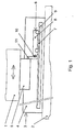
- Figure 1 shows schematically the bed 2, for example a processing or measuring machine on which a machine slide 1 displaceable in the direction of the arrow is.
- the total of 3 guided tour for the carriage 1 is a known per se Linear guide, which is a guide rail 4 with hardened and ground guide surfaces, where a car 5 via not shown Roller or ball elements is displaceable.
- the Carriage 5 of the linear guide 3 is with the machine slide 1 connected, its relative position to the machine bed 2 can be measured or adjusted should.
- Linear guides of the aforementioned type are described for example in the magazine "Industrie itatir "18/92, pages 43 to 45.
- the leadership according to the above principle can not in shown a curved guide rail have, for example, according to the type of sheet guide according to the magazine "Helpion" no. 39 of 09/29/1994, page 23.
- FIGs 1 and 2 is an open length measuring device 6 as a separate, pre-assembled unit attached to the guide rail 4.
- the length measuring device 6 has a scale 7 on one Carrier 9 is provided and by a scanning head 8 sampled to generate electrical measurement signals becomes.
- the carrier 9 serves as an auxiliary guide for the scanning head 8, which suitably via ball bearings slides thereon and by means of a clutch 10 a driver 11 is connected, which in turn is attached to the carriage 5 of the linear guide 3.
- the Coupling 10 consists of elements in the simplest case with a curved and flat surface that are kept in contact by means of a tension spring.
- the clutch 10 causes the scanning head 8 only coupled rigidly to the carriage 5 in the measuring direction and in other directions is articulated.
- the scanning head 8 on its support part in height the division plane of the scale 7 coupled, in Figure 2, however, at the level of the neutral fiber of the Scale 7 (such couplings are in themselves known for example from DE-PS 22 19 624).
- the length measuring device 6 is in the embodiment an incremental measuring device according to the principle of the photoelectric shown in Figure 8 Arrangement works.
- the on the linear guide 3 length measuring device according to the invention 6 can also be an absolute measuring device be and it is also any physical Functional principle conceivable, for example magnetic, inductive or capacitive type.
- FIGs 3 and 4 show an encapsulated incremental Length measuring device 6, which again as a separate, pre-assembled unit on the guide rail 4 of the linear guide 3 is attached.
- An encapsulated one Length measuring device 6 of this type is shown in FIG 8 is shown schematically. It has core elements a scale 7 in the form of a grid division, that of a corresponding grating in the scanning head 8 for generating electrical measurement signals is scanned.
- the scale 7 is on one Carrier 9, with as an auxiliary guide for the on it sliding scanning head 8 is used on the driver 11 is articulated.
- the elements scale 7 and scanning head 8 of the photoelectric length measuring device 6 are housed in a housing 12, that by means of flexible sealing lips 13 Rubber or plastic is covered.
- the encapsulated length measuring device 6 can vary according to physical Principles work as related to above Figures 1 and 2 already described. Open and encapsulated length measuring devices 6, as in the invention as separate, pre-assembled units the linear guide 3 provided, can in itself Company brochure "HEIDENHAIN delivery overview” Issued August 1994, pages 10 to 17 become.
- Figure 5 is an encapsulated length measuring device 6 via a connecting means in the form of an interchangeable coupling 14 on the guide rail 4 of the linear guide 3 easy to assemble and interchangeably attached.
- the interchangeable coupling 14 is of the type Swallowtail pairing trained.
- the receiving groove is located in the guide rail 4, the dovetail-shaped projection on the length measuring device 6.
- Figure 6 shows a linear guide 3, in the invention an encapsulated length measuring device 6 via a mounting rail 15 on the guide rail 4 is attached.
- the mounting rail 15, the after Type of a sliding block in the guide rail 4 engages, is by means of screws 16 on the Guide rail 4 clamped. It is also conceivable the mounting rail on the guide rail fasten and between the mounting rail and the Length measuring device to provide an interchangeable coupling.
- FIG. 7 shows a linear guide 3, which is attached to a mounting rail 15 1 , on which the encapsulated length measuring device 6 is also exchangeably fastened, which is connected to the carriage 5 via the driver 11.
Landscapes
- Engineering & Computer Science (AREA)
- General Engineering & Computer Science (AREA)
- Mechanical Engineering (AREA)
- Physics & Mathematics (AREA)
- General Physics & Mathematics (AREA)
- Length Measuring Devices With Unspecified Measuring Means (AREA)
- Details Of Measuring And Other Instruments (AREA)
- Fuel-Injection Apparatus (AREA)
- Valve-Gear Or Valve Arrangements (AREA)
- Devices For Conveying Motion By Means Of Endless Flexible Members (AREA)
- Electrical Discharge Machining, Electrochemical Machining, And Combined Machining (AREA)
- A Measuring Device Byusing Mechanical Method (AREA)
Claims (19)
- Système de guidage linéaire ou courbe comprenantdans lequelun rail de guidage (4) rectiligne ou courbe en tant qu'unité de construction indépendante et un chariot (5) guidé en translation sur celui-ci, le rail de guidage (4) étant fixé à un banc de machine (2) et le chariot (5) pouvant être lié à un chariot de machine (1),un dispositif de mesure (6) préassemblé, avec une règle (7) et une tête de palpage (8) montées dans un boítier (12), qui est associé au rail de guidage (4) pour mesurer la course de déplacement du chariot (5), le dispositif de mesure (6) étant placé sur le rail de guidage (4) en tant qu'unité de construction préassemblée,le dispositif de mesure (6) comporte un moyen de guidage auxiliaire (9) séparé du rail de guidage (4), sur lequel la tête de palpage (8) est guidée etla tête de palpage (8) du dispositif de mesure (6) est couplée au chariot (5) associé au rail de guidage (4) par l'intermédiaire d'un accouplement (10) rigide dans la direction de mesure, mais articulé dans les autres directions.
- Système de guidage selon la revendication 1, caractérisé en ce que le moyen de guidage auxiliaire (9, 12) est formé de la règle elle-même et/ou d'une unité de construction séparée ou du boítier (12).
- Système de guidage selon la revendication 1, caractérisé en ce que des moyens de liaison (14) quicoopèrent avec le rail de guidage (4) et le dispositif de mesure (6) sont prévus sous la forme d'un accouplement démontable pour la fixation avec possibilité de démontage du dispositif de mesure (6) sur le rail de guidage (4).
- Système de guidage selon la revendication 1, caractérisé en ce que le dispositif de mesure (6) est fixé au rail de guidage (4) par l'intermédiaire d'un rail de montage (15; 151) séparé.
- Système de guidage selon la revendication 3, caractérisé en ce que le dispositif de mesure (6) est fixé à un rail de montage (15) et en ce que les moyens de liaison sous la forme d'un accouplement démontable sont prévus directement sur le rail de guidage (4) et sur une face du rail de montage (15) tournée vers celui-ci.
- Système de guidage selon la revendication 3, caractérisé en ce que le dispositif de mesure (6) est fixé à un rail de montage (15) et en ce que des moyens de liaison entre le rail de montage (15) fixé au rail de guidage (4) et le dispositif de mesure (6) sont prévus sous la forme d'un accouplement démontable.
- Système de guidage selon la revendication 3, caractérisé en ce que les moyens de liaison (14) pour la fixation démontable du dispositif de mesure (6) au rail de montage (15) est conformée en éléments qui s'interpénètrent avec complémentarité de formes, pévus sur les ensembles à assembler.
- Système de guidage selon la revendication 7, caractérisé en ce que les moyens de liaison (14) qui s'interpénètrent avec complémentarité de formes sont formés d'éléments associés de type à queue d'aronde.
- Système de guidage selon la revendication 8, caractérisé en ce qu'une rainure de montage en queue d'aronde est prévue dans le rail de guidage (4) et que la pièce associée qui s'engage dans celle-ci avec complémentarité de formes est conformée en saillie sur le dispositif de mesure (6) ou sur le support de celui-ci.
- Système de guidage selon la revendication 3, caractérisé en ce que le dispositif de mesure (6), monté avec possibilité de démontage sur le rail de guidage (4), est fixé sans possibilité de déplacement au rail de guidage (4) à l'aide d'au moins un élément de serrage (16).
- Système de guidage selon la revendication 10, caractérisé en ce que les éléments de serrage (16) agissent directement sur les moyens de liaison au rail de guidage (4) et le dispositif de mesure (6) ou le support de celui-ci.
- Système de guidage selon la revendication 3, caractérisé en ce que la règle (7) et la tête de palpage (8) du dispositif de mesure (6) sont enfermés dans un boítier (12) formant rail et en ce que le boítier (12) est fixé de manière démontable au moyen des éléments de liaison (14) sur le côté du rail de guidage (4).
- Système de guidage selon la revendication 12, caractérisé en ce que le boítier (12) formant rail comporte une fente qui est fermée par des lèvres d'étanchéité (13) souples, entre lesquelles s'étend un entraíneur (11), qui est relié d'un côté à la tête de palpage (8) par l'intermédiaire d'un moyen d'accouplement (10) rigide dans la direction de mesure mais articulé dans les autres directions, et de l'autre est fixé au chariot (5) coulissant du rail de guidage (4).
- Système de guidage selon la revendication 3, caractérisé en ce qu'une saillie en queue d'aronde est prévue sur le boítier (12), laquelle saillie s'engage dans une rainure de montage en queue d'aronde aménagée dans le rail de guidage (4).
- Système de guidage selon la revendication 3, caractérisé en ce que le boítier (12) est fixé à un rail de montage (15), sur lequel il est prévu une saillie qui s'engage dans une rainure de montage aménagée directement dans le rail de guidage (4).
- Système de guidage selon la revendication 1, caractérisé en ce que la règle ou son support - par exemple sous la forme d'un boítier d'encapsulage - est relié d'une manière exempte de contraintes par des éléments compensateurs de type articulé, avantageusement par ses extrémités au rail de guidage (4).
- Système de guidage selon la revendication 1, caractérisé en ce que la graduation de mesure de la règle (7) est située à l'extérieur de la fibre neutre et en ce que la tête de palpage (8) est guidée parallèlement au plan de division et est couplée à son élément de support au niveau de la fibre neutre de la règle (7).
- Système de guidage selon la revendication 1, caractérisé en ce que la tête de palpage (8) guidée sur le moyen de guidage auxiliaire (9) au niveau de sa partie de support est couplée activement dans le plan de division de la règle (7).
- Système de guidage selon la revendication 1, caractérisé en ce que le chariot (5) repose sur le rail de guidage (4) rectiligne ou courbe par des éléments à rouleaux ou des éléments à billes.
Priority Applications (1)
| Application Number | Priority Date | Filing Date | Title |
|---|---|---|---|
| DE29522402U DE29522402U1 (de) | 1994-10-25 | 1995-09-20 | Führung |
Applications Claiming Priority (2)
| Application Number | Priority Date | Filing Date | Title |
|---|---|---|---|
| DE4438079A DE4438079A1 (de) | 1994-10-25 | 1994-10-25 | Führung |
| DE4438079 | 1994-10-25 |
Publications (3)
| Publication Number | Publication Date |
|---|---|
| EP0709655A2 EP0709655A2 (fr) | 1996-05-01 |
| EP0709655A3 EP0709655A3 (fr) | 1998-08-12 |
| EP0709655B1 true EP0709655B1 (fr) | 2001-12-05 |
Family
ID=6531633
Family Applications (1)
| Application Number | Title | Priority Date | Filing Date |
|---|---|---|---|
| EP95114778A Expired - Lifetime EP0709655B1 (fr) | 1994-10-25 | 1995-09-20 | Guidage |
Country Status (5)
| Country | Link |
|---|---|
| US (1) | US5687489A (fr) |
| EP (1) | EP0709655B1 (fr) |
| JP (1) | JP3023407B2 (fr) |
| AT (1) | ATE210279T1 (fr) |
| DE (2) | DE4438079A1 (fr) |
Cited By (1)
| Publication number | Priority date | Publication date | Assignee | Title |
|---|---|---|---|---|
| DE10214427B4 (de) * | 2002-03-30 | 2015-03-12 | Dr. Johannes Heidenhain Gmbh | Längenmeßeinrichtung und Linearführungseinheit |
Families Citing this family (24)
| Publication number | Priority date | Publication date | Assignee | Title |
|---|---|---|---|---|
| DE19526517C2 (de) * | 1995-07-20 | 2000-08-24 | Zeiss Carl Jena Gmbh | Anordnung zur Befestigung einer Längenmeßeinrichtung |
| DE19711271C2 (de) * | 1997-03-18 | 1999-04-29 | Zeiss Carl Jena Gmbh | Längenmeßsystem |
| DE19854318A1 (de) * | 1998-11-25 | 2000-05-31 | Heidenhain Gmbh Dr Johannes | Längenmeßeinrichtung |
| US6327791B1 (en) | 1999-06-09 | 2001-12-11 | The Government Of The United States As Represented By The Secretary Of Commerce | Chain code position detector |
| DE19943729A1 (de) * | 1999-09-03 | 2001-03-08 | Heidenhain Gmbh Dr Johannes | Wegmeßsystem |
| JP2001208530A (ja) * | 2000-01-26 | 2001-08-03 | Asanuma Giken:Kk | 計測機検査用計測マスタのセッティング装置 |
| JP4434452B2 (ja) * | 2000-08-15 | 2010-03-17 | ソニーマニュファクチュアリングシステムズ株式会社 | 測尺装置 |
| DE10204611B4 (de) * | 2002-02-05 | 2007-04-05 | Dr. Johannes Heidenhain Gmbh | Verfahren und Vorrichtung zum Anbringen eines Maßstabes oder Maßstabträgers |
| JP4509483B2 (ja) * | 2002-03-30 | 2010-07-21 | ドクトル・ヨハネス・ハイデンハイン・ゲゼルシヤフト・ミツト・ベシユレンクテル・ハフツング | リニアエンコーダ及びリニアガイドユニット |
| DE10214426B4 (de) * | 2002-03-30 | 2015-03-05 | Dr. Johannes Heidenhain Gmbh | Längenmesseinrichtung und Linearführungseinheit |
| US6739067B2 (en) * | 2002-04-25 | 2004-05-25 | Acu-Rite, Inc. | Cover for a sealed linear encoder and a sealed linear encoder |
| DE102004007070B3 (de) * | 2004-02-13 | 2005-09-29 | Hess Maschinenfabrik Gmbh & Co. Kg | Betonsteinmaschine mit einem über einen Linearantrieb verschiebbaren Teil |
| JP2006043866A (ja) * | 2004-06-30 | 2006-02-16 | Fanuc Ltd | パレット交換機能を有する工作機械及びパレット交換方法 |
| DE102005021345A1 (de) * | 2005-05-04 | 2006-11-09 | Schaeffler Kg | Linearführungseinheit mit Längenmesssystem |
| DE102005057012A1 (de) * | 2005-11-30 | 2007-05-31 | Bosch Rexroth Aktiengesellschaft | Positionsmesseinrichtung mit Führung |
| DE102006003980A1 (de) | 2006-01-27 | 2007-08-02 | Schaeffler Kg | Linearführungseinheit mit Längenmesssystem |
| DE102007009461A1 (de) * | 2007-01-25 | 2008-07-31 | Schaeffler Kg | Führungsschiene einer Linearführung |
| GB0811076D0 (en) * | 2008-06-17 | 2008-07-23 | Renishaw Plc | Scale track |
| GB0902547D0 (en) | 2009-02-16 | 2009-04-01 | Renishaw Plc | Encoder scale member and method for mounting |
| DE102010045439B4 (de) * | 2010-09-15 | 2014-04-24 | Fibro Gmbh | Rundtisch |
| DE102010054102A1 (de) * | 2010-12-10 | 2012-06-14 | Robert Bosch Gmbh | Linearbewegungsvorrichtung mit gesonderter Maßverkörperung |
| DE102017206584A1 (de) * | 2017-04-19 | 2018-10-25 | Robert Bosch Gmbh | Linearbewegungsvorrichtung mit Sensorhalter |
| DE102018207638A1 (de) * | 2018-05-16 | 2019-11-21 | Robert Bosch Gmbh | Führungswagen für eine Linearbewegungsvorrichtung, eine Linearbewegungs-vorrichtung und ein Verfahren |
| TWI666421B (zh) * | 2018-07-10 | 2019-07-21 | 英屬維京群島商詮優科技有限公司 | 自動化設備之位移量測機構 |
Citations (1)
| Publication number | Priority date | Publication date | Assignee | Title |
|---|---|---|---|---|
| US3910703A (en) * | 1972-10-06 | 1975-10-07 | Bausch & Lomb | Measuring apparatus using the moire fringe concept of measurement |
Family Cites Families (17)
| Publication number | Priority date | Publication date | Assignee | Title |
|---|---|---|---|---|
| DE2820753C2 (de) * | 1978-05-12 | 1980-03-06 | Dr. Johannes Heidenhain Gmbh, 8225 Traunreut | Einrichtung zur Fehlerkorrektur bei Positionsmeßsystemen |
| JPS5522664U (fr) * | 1978-07-31 | 1980-02-14 | ||
| DE2900113C2 (de) * | 1979-01-03 | 1985-08-29 | Dr. Johannes Heidenhain Gmbh, 8225 Traunreut | Längenmeßeinrichtung mit längsverschieblichem Maßstab |
| JPS589007A (ja) * | 1981-07-08 | 1983-01-19 | Nippon Kogaku Kk <Nikon> | 測長装置 |
| US4495703A (en) * | 1981-11-25 | 1985-01-29 | Mitutoyo Mfg. Co., Ltd. | Coordinate measuring instrument |
| DE3201887C2 (de) * | 1982-01-22 | 1983-11-24 | Dr. Johannes Heidenhain Gmbh, 8225 Traunreut | Längenmeßeinrichtung |
| DE3302643C2 (de) * | 1983-01-27 | 1987-01-08 | Dr. Johannes Heidenhain Gmbh, 8225 Traunreut | Spanneinrichtung für eine Längenmeßeinrichtung |
| US4586760A (en) | 1984-06-01 | 1986-05-06 | Bausch & Lomb Incorporated | Measuring scale casing and mounting spar |
| AT379449B (de) * | 1984-07-03 | 1986-01-10 | R S F Elektronik Ohg Rechtsfor | Laengenmesseinrichtung |
| DE8525587U1 (de) | 1985-09-07 | 1987-01-08 | Robert Bosch Gmbh, 7000 Stuttgart | Wegmeßeinrichtung |
| DE3624485A1 (de) * | 1986-07-19 | 1988-01-21 | Heidenhain Gmbh Dr Johannes | Positionsmesseinrichtung |
| GB8705302D0 (en) * | 1987-03-06 | 1987-04-08 | Renishaw Plc | Combined scale & interferometer |
| DE8717824U1 (de) * | 1987-04-23 | 1990-05-03 | Dr. Johannes Heidenhain Gmbh, 8225 Traunreut | Positionsmeßeinrichtung |
| DE8808811U1 (de) | 1988-07-08 | 1988-08-18 | Mettler Instrumente AG, Greifensee | Befestigungsvorrichtung für einen Maßkörper in einer Längenmeßanordnung |
| JP2584875B2 (ja) | 1989-11-08 | 1997-02-26 | テイエチケー 株式会社 | 直線摺動用ベアリング |
| FR2660992B1 (fr) | 1990-04-17 | 1992-07-31 | Ampere | Procede et dispositif de propulsion electrodynamique. |
| DE9006138U1 (de) * | 1990-05-31 | 1990-08-02 | Dr. Johannes Heidenhain Gmbh, 8225 Traunreut | Positionsmeßeinrichtung |
-
1994
- 1994-10-25 DE DE4438079A patent/DE4438079A1/de not_active Withdrawn
-
1995
- 1995-09-20 EP EP95114778A patent/EP0709655B1/fr not_active Expired - Lifetime
- 1995-09-20 AT AT95114778T patent/ATE210279T1/de not_active IP Right Cessation
- 1995-09-20 DE DE59509909T patent/DE59509909D1/de not_active Expired - Lifetime
- 1995-10-23 JP JP7274382A patent/JP3023407B2/ja not_active Expired - Fee Related
- 1995-10-23 US US08/546,803 patent/US5687489A/en not_active Expired - Lifetime
Patent Citations (1)
| Publication number | Priority date | Publication date | Assignee | Title |
|---|---|---|---|---|
| US3910703A (en) * | 1972-10-06 | 1975-10-07 | Bausch & Lomb | Measuring apparatus using the moire fringe concept of measurement |
Cited By (1)
| Publication number | Priority date | Publication date | Assignee | Title |
|---|---|---|---|---|
| DE10214427B4 (de) * | 2002-03-30 | 2015-03-12 | Dr. Johannes Heidenhain Gmbh | Längenmeßeinrichtung und Linearführungseinheit |
Also Published As
| Publication number | Publication date |
|---|---|
| JPH08210834A (ja) | 1996-08-20 |
| EP0709655A3 (fr) | 1998-08-12 |
| JP3023407B2 (ja) | 2000-03-21 |
| ATE210279T1 (de) | 2001-12-15 |
| DE4438079A1 (de) | 1996-05-02 |
| US5687489A (en) | 1997-11-18 |
| EP0709655A2 (fr) | 1996-05-01 |
| DE59509909D1 (de) | 2002-01-17 |
Similar Documents
| Publication | Publication Date | Title |
|---|---|---|
| EP0709655B1 (fr) | Guidage | |
| DE19526517C1 (de) | Anordnung zur Befestigung einer Längenmeßeinrichtung | |
| EP2132864B1 (fr) | Dispositif d'entrainement electrique lineaire direct avec un stator presentant deux rails de guidage pour le guidage lineaire d'un coulisseau entraine | |
| EP0868774B1 (fr) | Moteur lineaire synchrone electrique et procede de determination du decalage de commutation d'un dispositif d'entrainement lineaire pourvu d'un tel moteur lineaire | |
| DE3334398C1 (de) | Messeinrichtung | |
| DE102011079464A1 (de) | Längenmesseinrichtung | |
| EP1742023A1 (fr) | Guidage linéaire avec appareil pour mesurer la position | |
| EP1982148A2 (fr) | Unité de guidage linéaire équipée d'un système de mesure de longueur | |
| DE19700367C2 (de) | Verfahren und Montagevorrichtung zum gerichteten Anbringen eines Maßbandes | |
| DE3208591A1 (de) | Laengen- oder winkelmesssystem | |
| DE19810771C1 (de) | Basis-Profil für die Spanntechnik zu vermessender Werkstücke | |
| EP0253992A2 (fr) | Dispositif de mesure de position | |
| DE19941587B4 (de) | Linearlager mit einer Einrichtung zum Messen | |
| DE29522402U1 (de) | Führung | |
| DE10214426B4 (de) | Längenmesseinrichtung und Linearführungseinheit | |
| DE10229885B4 (de) | Verfahren und Vorrichtung zum Anbringen eines Maßstabs oder Maßstabträgers oder einer Maßstabführung | |
| DE3419527C2 (fr) | ||
| DE10214427B4 (de) | Längenmeßeinrichtung und Linearführungseinheit | |
| EP0077318A2 (fr) | Dispositif pour mesurer deux chemins de rouleaux opposés d'une installation de coulée continue | |
| DE69601251T2 (de) | Tischvorrichtung für Werkzeugmaschinen | |
| DE102017201230A1 (de) | Linearbewegungsvorrichtung mit Lebensdauerüberwachung | |
| EP0805954B1 (fr) | Appareil de mesure de la longueur servant a mesurer la position relative de deux objets | |
| EP1366849B1 (fr) | Guidage linéaire | |
| EP0214615A1 (fr) | Appareil de mesure du trajet | |
| DE3608392C2 (fr) |
Legal Events
| Date | Code | Title | Description |
|---|---|---|---|
| PUAI | Public reference made under article 153(3) epc to a published international application that has entered the european phase |
Free format text: ORIGINAL CODE: 0009012 |
|
| AK | Designated contracting states |
Kind code of ref document: A2 Designated state(s): AT CH DE FR GB IT LI |
|
| PUAL | Search report despatched |
Free format text: ORIGINAL CODE: 0009013 |
|
| AK | Designated contracting states |
Kind code of ref document: A3 Designated state(s): AT CH DE FR GB IT LI |
|
| 17P | Request for examination filed |
Effective date: 19990212 |
|
| 17Q | First examination report despatched |
Effective date: 20000703 |
|
| GRAG | Despatch of communication of intention to grant |
Free format text: ORIGINAL CODE: EPIDOS AGRA |
|
| GRAG | Despatch of communication of intention to grant |
Free format text: ORIGINAL CODE: EPIDOS AGRA |
|
| GRAH | Despatch of communication of intention to grant a patent |
Free format text: ORIGINAL CODE: EPIDOS IGRA |
|
| GRAH | Despatch of communication of intention to grant a patent |
Free format text: ORIGINAL CODE: EPIDOS IGRA |
|
| ITF | It: translation for a ep patent filed | ||
| GRAA | (expected) grant |
Free format text: ORIGINAL CODE: 0009210 |
|
| AK | Designated contracting states |
Kind code of ref document: B1 Designated state(s): AT CH DE FR GB IT LI |
|
| REF | Corresponds to: |
Ref document number: 210279 Country of ref document: AT Date of ref document: 20011215 Kind code of ref document: T |
|
| REG | Reference to a national code |
Ref country code: CH Ref legal event code: NV Representative=s name: TROESCH SCHEIDEGGER WERNER AG Ref country code: CH Ref legal event code: EP |
|
| REG | Reference to a national code |
Ref country code: GB Ref legal event code: IF02 |
|
| REF | Corresponds to: |
Ref document number: 59509909 Country of ref document: DE Date of ref document: 20020117 |
|
| GBT | Gb: translation of ep patent filed (gb section 77(6)(a)/1977) |
Effective date: 20020129 |
|
| ET | Fr: translation filed | ||
| PLBE | No opposition filed within time limit |
Free format text: ORIGINAL CODE: 0009261 |
|
| STAA | Information on the status of an ep patent application or granted ep patent |
Free format text: STATUS: NO OPPOSITION FILED WITHIN TIME LIMIT |
|
| 26N | No opposition filed | ||
| PGFP | Annual fee paid to national office [announced via postgrant information from national office to epo] |
Ref country code: AT Payment date: 20080915 Year of fee payment: 14 |
|
| PG25 | Lapsed in a contracting state [announced via postgrant information from national office to epo] |
Ref country code: AT Free format text: LAPSE BECAUSE OF NON-PAYMENT OF DUE FEES Effective date: 20090920 |
|
| PGFP | Annual fee paid to national office [announced via postgrant information from national office to epo] |
Ref country code: CH Payment date: 20100923 Year of fee payment: 16 |
|
| PGFP | Annual fee paid to national office [announced via postgrant information from national office to epo] |
Ref country code: IT Payment date: 20100922 Year of fee payment: 16 Ref country code: FR Payment date: 20101005 Year of fee payment: 16 |
|
| PGFP | Annual fee paid to national office [announced via postgrant information from national office to epo] |
Ref country code: GB Payment date: 20100921 Year of fee payment: 16 |
|
| PGFP | Annual fee paid to national office [announced via postgrant information from national office to epo] |
Ref country code: DE Payment date: 20110923 Year of fee payment: 17 |
|
| REG | Reference to a national code |
Ref country code: CH Ref legal event code: PL |
|
| GBPC | Gb: european patent ceased through non-payment of renewal fee |
Effective date: 20110920 |
|
| PG25 | Lapsed in a contracting state [announced via postgrant information from national office to epo] |
Ref country code: IT Free format text: LAPSE BECAUSE OF NON-PAYMENT OF DUE FEES Effective date: 20110920 |
|
| REG | Reference to a national code |
Ref country code: FR Ref legal event code: ST Effective date: 20120531 |
|
| PG25 | Lapsed in a contracting state [announced via postgrant information from national office to epo] |
Ref country code: CH Free format text: LAPSE BECAUSE OF NON-PAYMENT OF DUE FEES Effective date: 20110930 Ref country code: LI Free format text: LAPSE BECAUSE OF NON-PAYMENT OF DUE FEES Effective date: 20110930 |
|
| PG25 | Lapsed in a contracting state [announced via postgrant information from national office to epo] |
Ref country code: FR Free format text: LAPSE BECAUSE OF NON-PAYMENT OF DUE FEES Effective date: 20110930 Ref country code: GB Free format text: LAPSE BECAUSE OF NON-PAYMENT OF DUE FEES Effective date: 20110920 |
|
| PG25 | Lapsed in a contracting state [announced via postgrant information from national office to epo] |
Ref country code: DE Free format text: LAPSE BECAUSE OF NON-PAYMENT OF DUE FEES Effective date: 20130403 |
|
| REG | Reference to a national code |
Ref country code: DE Ref legal event code: R119 Ref document number: 59509909 Country of ref document: DE Effective date: 20130403 |