EP0709842B1 - Aufzeichnung und Wiedergabe von Daten - Google Patents
Aufzeichnung und Wiedergabe von Daten Download PDFInfo
- Publication number
- EP0709842B1 EP0709842B1 EP95307569A EP95307569A EP0709842B1 EP 0709842 B1 EP0709842 B1 EP 0709842B1 EP 95307569 A EP95307569 A EP 95307569A EP 95307569 A EP95307569 A EP 95307569A EP 0709842 B1 EP0709842 B1 EP 0709842B1
- Authority
- EP
- European Patent Office
- Prior art keywords
- reference pattern
- gain
- disk
- data
- offset
- Prior art date
- Legal status (The legal status is an assumption and is not a legal conclusion. Google has not performed a legal analysis and makes no representation as to the accuracy of the status listed.)
- Expired - Lifetime
Links
Images


Classifications
-
- G—PHYSICS
- G11—INFORMATION STORAGE
- G11B—INFORMATION STORAGE BASED ON RELATIVE MOVEMENT BETWEEN RECORD CARRIER AND TRANSDUCER
- G11B7/00—Recording or reproducing by optical means, e.g. recording using a thermal beam of optical radiation by modifying optical properties or the physical structure, reproducing using an optical beam at lower power by sensing optical properties; Record carriers therefor
-
- G—PHYSICS
- G11—INFORMATION STORAGE
- G11B—INFORMATION STORAGE BASED ON RELATIVE MOVEMENT BETWEEN RECORD CARRIER AND TRANSDUCER
- G11B20/00—Signal processing not specific to the method of recording or reproducing; Circuits therefor
- G11B20/10—Digital recording or reproducing
- G11B20/10009—Improvement or modification of read or write signals
- G11B20/10046—Improvement or modification of read or write signals filtering or equalising, e.g. setting the tap weights of an FIR filter
- G11B20/10203—Improvement or modification of read or write signals filtering or equalising, e.g. setting the tap weights of an FIR filter baseline correction
-
- G—PHYSICS
- G11—INFORMATION STORAGE
- G11B—INFORMATION STORAGE BASED ON RELATIVE MOVEMENT BETWEEN RECORD CARRIER AND TRANSDUCER
- G11B11/00—Recording on or reproducing from the same record carrier wherein for these two operations the methods are covered by different main groups of groups G11B3/00 - G11B7/00 or by different subgroups of group G11B9/00; Record carriers therefor
- G11B11/10—Recording on or reproducing from the same record carrier wherein for these two operations the methods are covered by different main groups of groups G11B3/00 - G11B7/00 or by different subgroups of group G11B9/00; Record carriers therefor using recording by magnetic means or other means for magnetisation or demagnetisation of a record carrier, e.g. light induced spin magnetisation; Demagnetisation by thermal or stress means in the presence or not of an orienting magnetic field
- G11B11/105—Recording on or reproducing from the same record carrier wherein for these two operations the methods are covered by different main groups of groups G11B3/00 - G11B7/00 or by different subgroups of group G11B9/00; Record carriers therefor using recording by magnetic means or other means for magnetisation or demagnetisation of a record carrier, e.g. light induced spin magnetisation; Demagnetisation by thermal or stress means in the presence or not of an orienting magnetic field using a beam of light or a magnetic field for recording by change of magnetisation and a beam of light for reproducing, i.e. magneto-optical, e.g. light-induced thermomagnetic recording, spin magnetisation recording, Kerr or Faraday effect reproducing
- G11B11/10502—Recording on or reproducing from the same record carrier wherein for these two operations the methods are covered by different main groups of groups G11B3/00 - G11B7/00 or by different subgroups of group G11B9/00; Record carriers therefor using recording by magnetic means or other means for magnetisation or demagnetisation of a record carrier, e.g. light induced spin magnetisation; Demagnetisation by thermal or stress means in the presence or not of an orienting magnetic field using a beam of light or a magnetic field for recording by change of magnetisation and a beam of light for reproducing, i.e. magneto-optical, e.g. light-induced thermomagnetic recording, spin magnetisation recording, Kerr or Faraday effect reproducing characterised by the transducing operation to be executed
- G11B11/10515—Reproducing
-
- G—PHYSICS
- G11—INFORMATION STORAGE
- G11B—INFORMATION STORAGE BASED ON RELATIVE MOVEMENT BETWEEN RECORD CARRIER AND TRANSDUCER
- G11B11/00—Recording on or reproducing from the same record carrier wherein for these two operations the methods are covered by different main groups of groups G11B3/00 - G11B7/00 or by different subgroups of group G11B9/00; Record carriers therefor
- G11B11/10—Recording on or reproducing from the same record carrier wherein for these two operations the methods are covered by different main groups of groups G11B3/00 - G11B7/00 or by different subgroups of group G11B9/00; Record carriers therefor using recording by magnetic means or other means for magnetisation or demagnetisation of a record carrier, e.g. light induced spin magnetisation; Demagnetisation by thermal or stress means in the presence or not of an orienting magnetic field
- G11B11/105—Recording on or reproducing from the same record carrier wherein for these two operations the methods are covered by different main groups of groups G11B3/00 - G11B7/00 or by different subgroups of group G11B9/00; Record carriers therefor using recording by magnetic means or other means for magnetisation or demagnetisation of a record carrier, e.g. light induced spin magnetisation; Demagnetisation by thermal or stress means in the presence or not of an orienting magnetic field using a beam of light or a magnetic field for recording by change of magnetisation and a beam of light for reproducing, i.e. magneto-optical, e.g. light-induced thermomagnetic recording, spin magnetisation recording, Kerr or Faraday effect reproducing
- G11B11/10595—Control of operating function
-
- G—PHYSICS
- G11—INFORMATION STORAGE
- G11B—INFORMATION STORAGE BASED ON RELATIVE MOVEMENT BETWEEN RECORD CARRIER AND TRANSDUCER
- G11B20/00—Signal processing not specific to the method of recording or reproducing; Circuits therefor
- G11B20/10—Digital recording or reproducing
- G11B20/10009—Improvement or modification of read or write signals
- G11B20/10037—A/D conversion, D/A conversion, sampling, slicing and digital quantisation or adjusting parameters thereof
-
- G—PHYSICS
- G11—INFORMATION STORAGE
- G11B—INFORMATION STORAGE BASED ON RELATIVE MOVEMENT BETWEEN RECORD CARRIER AND TRANSDUCER
- G11B7/00—Recording or reproducing by optical means, e.g. recording using a thermal beam of optical radiation by modifying optical properties or the physical structure, reproducing using an optical beam at lower power by sensing optical properties; Record carriers therefor
- G11B7/004—Recording, reproducing or erasing methods; Read, write or erase circuits therefor
- G11B7/005—Reproducing
-
- G—PHYSICS
- G11—INFORMATION STORAGE
- G11B—INFORMATION STORAGE BASED ON RELATIVE MOVEMENT BETWEEN RECORD CARRIER AND TRANSDUCER
- G11B7/00—Recording or reproducing by optical means, e.g. recording using a thermal beam of optical radiation by modifying optical properties or the physical structure, reproducing using an optical beam at lower power by sensing optical properties; Record carriers therefor
- G11B7/007—Arrangement of the information on the record carrier, e.g. form of tracks, actual track shape, e.g. wobbled, or cross-section, e.g. v-shaped; Sequential information structures, e.g. sectoring or header formats within a track
- G11B7/00745—Sectoring or header formats within a track
Definitions
- This invention relates generally to recording and reproduction of data and can be applied to gain and offset control apparatus for recording and/or reproducing data from an optical disk, preferably a magneto-optical disk, and more particularly, to such apparatus that is controlled in response to reference patterns read from the disk.
- Optical disks are recorded with a spiral track or with concentric tracks in which information is represented by pits. Such disks are driven either at a constant angular velocity (CAV), whereby the density of the pits generally decreases at those tracks located at a greater radius from the center, or at a constant linear velocity (CLV), whereby the rotary speed of the disk increases as the radius of the track being scanned increases such that the density of the pits generally is constant over the entire disk.
- CAV constant angular velocity
- CLV constant linear velocity
- optical disks generally includes useful information, such as audio information for an audio disk, video and video/audio information for a video disk and computer file data for a computer disk (such as a CD ROM).
- useful information such as audio information for an audio disk, video and video/audio information for a video disk and computer file data for a computer disk (such as a CD ROM).
- optical disks include address information to permit a user to access a desired portion of the disk, such as a desired data sector, and servo information which is used for tracking control (i.e. to assure "center-line” tracking of a recording or pickup head) and to synchronize the clock of the disk drive with the actual speed of the disk.
- Servo information may be recorded in a pre-existing groove that is formed continuously along the track of a spiral-track optical disk or, alternatively, the servo information may be distributed along the spiral or concentric tracks in discrete servo areas. For example, when manufacturing the optical disk, such discrete servo areas may be pre-formed as part of the manufacturing process.
- the amplitude as well as the offset of the reproduced signals may fluctuate because of fluctuations inherent in the optical system.
- Such optical system fluctuations are attributed to fluctuations in the disk speed, fluctuations occasioned by variations or changes in circuit parameters or fluctuations due to changes in the reflectance or other optical properties of the recording medium or changes in the Kerr rotation angle.
- JP-A-5046991 discloses an optical disk having pits with a mark length at which RF signals have a saturated level and no-pit sections. These pits are pre-cut onto the disk in a ROM portion of the disk containing the sector header and are used to calculate gain and offset levels. They are not located in the same portion of the disk that data is recorded on, rather being recorded in the prescribed header H1 section.
- JP-A-5.047.11 discloses an optical disk in which a reference signal is previously recorded in a reference recording region.
- the present invention is set out in claim 1.
- apparatus for reproducing data from an optical disk, such as a magneto-optical disk, the data being recorded in a track which contains a reference pattern exhibiting distinct amplitude levels.
- An optical head reads data in the track and supplies a signal representing such data to a gain control circuit having an adjustable gain.
- the output from the gain control circuit is supplied to an offset control circuit which is adjustable to vary the offset of the gain-controlled signal.
- a level detector detects upper and lower amplitude levels in the reference pattern read by the optical head and supplied through the gain and offset control circuits; and amplitude and offset control values are calculated from the upper and lower amplitude levels to adjust the gain and offset of the gain and offset control circuits, respectively, whereby data read by the optical head is reproduced with predetermined gain and offset.
- a further aspect of the invention relates to recording/reproducing apparatus which records information in sectors in a track as pits, with each sector being comprised of data segments interspersed with servo areas.
- useful information as well as a reference pattern are recorded in a sector, with the reference pattern being recorded in a number of data segments located in a leading position of each sector and exhibiting distinct amplitude levels.
- the aforementioned gain and offset control values are calculated in response to the detection of these distinct amplitude levels when an optical head reads the reference pattern.
- Embodiments of the present invention provide an improved technique for recovering data from an optical disk, such as a magneto-optical disk, notwithstanding fluctuations in the operating parameters of the disk or the disk drive that is used to play the disk.
- embodiments of this invention provide gain and offset control apparatus that are adjustable automatically to assure accurate recovery of useful data reproduced from the disk.
- Fig. 1 there is illustrated a portion of a track on the magneto-optical disk with which the present embodiment finds particular application.
- the portion of the track shown in Fig. 1 may be a portion of a spiral track recorded continuously from an inner radius to an outer radius or, alternatively, it may be a portion of one of several concentric tracks. It will be appreciated that the present embodiment is not contingent on whether a spiral track or concentric tracks are recorded on the disk. To account for the use of one spiral track or several concentric tracks, the description herein refers to a "turn" which is intended to mean one complete concentric track or one 360° rotation of a spiral track.
- Each address segment contains information (it is appreciated that in the magneto-optical disk, information is recorded as pits) which identifies the radial position of the address segment and also the circular position thereof.
- the data segments include useful data, such as audio information (if the magneto-optical disk is an audio disk), video information (if the magneto-optical disk is a video disk) or computer file information (if the magneto-optical disk is a computer storage medium).
- a frame is composed of 1 address segment and 13 data segments; and there are 100 frames recorded in a complete turn. Thus, each turn consists of 100 address segments and 1,300 data segments.
- a unit of data is recorded as a pit; and as will be seen from Figs. 2A-2D, the duration of each pit is approximately two clock cycles, with a clock cycle being generated by a reference clock (or system clock) in the disk drive shown in Fig. 5.
- a reference clock or system clock
- Each segment whether an address segment or a data segment, is comprised of 216 clock cycles and each segment contains a servo portion (or area) ARs having a duration of 24 clock cycles and a data portion ARd having a duration of 192 clock cycles.
- the data portion of the address segment ASEG includes an address section ARda which contains address information and a laser control section ARdb which is used by the disk drive components shown in Fig. 5 to control various operating parameters of the laser beam used to scan the magneto-optical disk.
- Each servo portion (or area) ARs of the address segment and of the different types of data segments is shown in Figs. 2A-2D.
- Each servo portion (or area) contains three pre-recorded pits, identified as a mark pit P A and wobble pits P B and P C .
- the positions of the wobble pits are fixed and the position of the mark pit is dependent upon the particular type of segment in which that mark pit is recorded. Referring first to the wobble pits P B and P C , these pits are located at clock cycles 11 and 16 and are offset from the center line of the track by, for example, 1 ⁇ 2 of a track pitch, as shown in Figs. 2A-2D. These wobble pits are used for tracking control.
- the scanning laser beam is offset, or displaced, from the center line of the track, the signal produced from one of the wobble pits P B or P C will be greater than the other.
- an indication of the direction and intensity of a tracking error is produced and may be readily compensated.
- pulses produced by scanning these pits will exhibit a frequency determined by the speed of the disk, thereby permitting a servo clock (from which system clock pulses are generated) to be synchronized therewith.
- each servo portion in each segment includes a section ARfs in which no pits are recorded.
- This section is known as a focus sample section having a duration of six clock cycles and is used to control the focusing servo operation of the disk drive.
- the format of the pits shown in Figs. 2A-2D is preferred because it minimizes that portion of the disk in which no pits are formed (known as the mirror portion), thereby reducing the possibility that "ghost pits" will be produced during the disk molding process. It is preferred, therefore, to record each pit with a duration of two clock cycles and to separate the pits in the servo portion by at least five clock cycles. Consequently, inter-pit interference may be kept desirably small.
- Mark pit P A recorded in the leading section of each servo portion, identifies the segment in which the mark pit is recorded as either an address segment ASEG or a data segment DSEG. If a data segment, the position of the mark pit P A also identifies the data segment as the first data segment in a sector, the last data segment in the sector or any other intermediate data segment in the sector. The number of segments in a sector is dependent upon the radial position of that sector. If the mark pit is recorded in clock cycles 3-4 of a segment, that pit identifies the segment as an address segment ASEG. If the mark pit is located at clock cycles 4-5, the pit identifies the segment as a data segment, and moreover, as the leading, or first, data segment in the sector.
- the pit identifies the segment as the last data segment of a sector. Finally, if the mark pit P A is located at clock cycles 6-7, the pit identifies the segment as any data segment, other than the first or last, in the sector.
- the presence and position of a mark pit are determined by generating sampling pulses at those clock cycles identified as A, B, C and D, shown in Figs. 2A-2D.
- sampling pulse A the segment in which that mark pit is located is identified as an address segment.
- the mark pit is sensed by sampling pulse B, the segment is detected as the first segment of a sector.
- the mark pit is sensed by sampling pulse C, the segment is detected as the last segment of a sector.
- the mark pit is sensed by sampling pulse D, the segment is detected as any intermediate segment in the sector.
- Fig. 3 schematically represents a section of useful information, or data, that is distributed in a number of data segments.
- the sector includes a reference area, a data area (referred to as user data), a reserved area UD, a cyclic redundancy code area CRC and an error correcting code area ECC.
- the reference area extends for a duration of 528 clock cycles, or 66 bytes (it will be seen that the reference area includes a reference pattern comprised of 64 bytes plus 2 bytes of a "O" pattern).
- the data area includes 2,048 bytes of user data (i.e. data that may be recorded by the user or data that is of interest to the user, such as audio, video or computer data).
- the reserved area extends for 40 bytes which may include, for example, 8 bytes of vendor data plus 32 bytes of data that may be recorded as the user sees fit.
- the CRC area extends for 8 bytes and the ECC area extends for 256 bytes.
- interspersed within the sector of 2,418 bytes are periodic servo areas, each being pre-recorded with the magneto-optical disk to provide the wobble bits discussed above.
- each byte exhibits a duration of 8 clock cycles (a clock cycle also is referred to herein as a data clock); and it is seen that a segment, whether it is a data segment or an address segment, extends from the beginning of one servo area to the beginning of the next. It is also seen that each address segment ASEG is pre-recorded with the magneto-optical disk; and user data is interrupted by the pre-recorded servo areas.
- a reference pattern is recorded at the beginning portion of each sector.
- the reference pattern is shown in Fig. 4A and is comprised of 64 bytes (or 512 clock cycles) of a repetitive reference pattern plus two bytes (or 16 clock cycles) of what is shown as a "0" pattern. From Pig. 1 it is seen that each servo area is comprised of 24 clock cycles and the immediately following data area is comprised of 192 clock cycles.
- the reference pattern which is comprised of 528 clock cycles, thus is recorded in the data areas of the respective segments such that, for example, the first 192 clock cycles of the reference pattern are recorded folloving the first servo area and then the next 192 clock cycles are recorded after the next-following servo area and then, after the address segment (and servo area), the remaining 144 clock cycles of the reference pattern are recorded. That is, the reference pattern is distributed into data segments; and it is seen that the last portion of the reference pattern fills only a portion of a data segment, the remainder of which contains useful data, as shown more clearly in Fig. 4B. Stated otherwise, the reference pattern is distributed over the leading segments of a data sector. It is appreoiated that no portion of the reference pattern is recorded in the address segment shown in Fig. 4B because the address segment is pre-recorded throughout a turn, as discussed above in conjunction with Fig. 1.
- the reference pattern includes two distinct waveforms: a waveform identified as a "2T” pattern, wherein T is a clock cycle, and a waveform identified as the "8T” pattern.
- the "2T” pattern is represented as 110011001100... and the “8T” pattern is represented as 11111111000000001111111100....
- the "2T” pattern is referred to as the read clock/phase compensation area and the "8T” pattern is referred to as the level detection area.
- the "8T" patten exhibits two distinct amplitude levels, a minimum level and a maximum level, both of which are sampled and used to derive gain and offset control values for controlling the gain and offset of signals recovered from the recorded pits in order to interpret the pits as 0's and 1's.
- the "2T” pattern exhibits a substantially higher frequency (four times the frequency of the "8T” pattern) and is used to detect phase shifts due to changes in the rotary speed of the disk and also to synchronize with the disk rotation the clock signals generated by the disk drive.
- the reference pattern is repeated n times in the reference area of the data sector.
- FIG. 5 A block diagram of the disk drive used to record on and reproduce from the magneto-optical disk is shown in Fig. 5. More particularly, the disk drive is comprised of a drive section 200 and a control section 100. Commands and data are exchanged between the control section and the drive section; and data originates with and is destined for a host computer 300. Operations of the disk drive are controlled by a controller 101 which communicates with host computer 300 via a suitable interface, such as a SCSI interface. Controller 101 appends CRC and ECC codes to data originating with host computer 300 and intended to be recorded on, for example, disk 201 and also serves to detect such CRC and ECC codes from data that is reproduced from the disk in order to correct such reproduced data in the event that errors are present. The data thus corrected by controller 101 then is transmitted to the host computer.
- a controller 101 which communicates with host computer 300 via a suitable interface, such as a SCSI interface. Controller 101 appends CRC and ECC codes to data originating with host computer 300 and intended to be recorded on
- a digital signal processor 102 is included in control section 100 and functions to process the commands received from controller 101 so as to control drive section 200, thereby regulating the rotary speed of disk 201, the operation of the laser head and the operation of the magnetic head in the recording and reproduction of data.
- digital signal processor 102 transmits commands to a spindle driver 204 via an input/output (I/O) circuit 103 to control spindle motor 203 which rotates disk 201. If an MO disk, as an example, is loaded onto drive section 200 by a loading mechanism 202, digital signal processor 102 commands spindle driver 204 to drive spindle motor 203 such that the disk is brought up to proper operating speed.
- a suitable signal is supplied from spindle driver 204 via I/O circuit 103 to digital signal processor 102 indicating that the disk speed has been stabilized and that a read or write operation may begin.
- digital signal processor 102 controls pickup drive motors 205 to position the laser head either to the inner portion of disk 201 or to the outer portion thereof such that the laser beam is positioned outside the user information area.
- Motors 205 are controlled by a pulse width modulation (PWM) circuit 104 which, in turn, controls driver 105 to control the motors 205. While outside the useful information area, the laser optics are controlled to focus the laser beam and to adjust the power thereof.
- PWM pulse width modulation
- the bias current of laser diode 207 is set by laser driver 206 in response to the control signal LDbias supplied thereto from digital signal processor 102 via an input/output (I/O) circuit 106 and digital-to-analog (D/A) converter 107.
- the digital signal processor also controls a timing generator (STG) 108 via the DSP bus to control the laser driver to turn on laser diode 207 at the proper times.
- the laser beam emitted by the laser diode is reflected from disk 201 to a photodetector 208, the output of which is converted by a current-to-voltage (I/V) converter and matrix amplifier 209 to a voltage which represents the magnitude of the reflected laser beam.
- I/V current-to-voltage
- APC automatic power control
- This automatic power control signal is referred to as a "front" APC signal and is supplied by multiplexer 109 to A/D converter 110 for conversion into digital form so as to be supplied, via an input/output (I/O) interface circuit 111 to digital signal processor 102.
- the intensity of the reflected laser beam thus is detected by the digital signal processor to control the bias current supplied to the laser diode, thereby maintaining the proper intensity of the laser beam.
- I/V converter and amplifier 209 also generates a focusing error signal in response to the reflected laser beam picked up by detector 208; and this focusing error signal is supplied by multiplexer 109, A/D converter 110 and I/O interface 111 to digital signal processor 102.
- the digital signal processor responds to this focusing error signal to determine if the laser beam emitted by laser diode 207 is properly focused on disk 201. If not, the focusing lens (or lenses) of the laser optics is adjusted to provide proper focussing.
- a suitable control signal is supplied from digital signal processor 102 via the DSP bus to PWM circuit 104 which, in turn, controls focusing driver 105 to adjust the focus condition of the laser beam.
- I/V converter and amplifier 209 produces a playback RF signal (PRF) exhibiting a substantially constant amplitude.
- PRF playback RF signal
- This PRF signal is supplied to an A/D converter 113 by an analog signal processing circuit (ASP) 112 and thence to a clock generator (PLL) 114, which includes a phase locked loop but at this time is free running. Timing pulses are produced by frequency dividing the free running frequency of the clock generator by a pre-set divisor.
- Clock generator 114 controls an analog signal processing circuit (ASP) 115 to generate sampling pulses, or windows, at those times during which the wobble pits are expected, as discussed above in connection with Figs. 2A-2D. If such wobble pit detection is confirmed a predetermined number of successive times, clock generator 114 is recognized as being phase-locked to disk 201.
- ASP analog signal processing circuit
- the mark pits shown in Figs. 2A-2D are sensed in order to identify the particular segment being scanned by the laser beam.
- Clock generator 114 thus cooperates with ASP 115 to generate the sampling pulses, or windows, at position A, B, C and D (as best seen in Figs. 2A-2D) in order to determine the position of the mark pit in each servo area. It is appreciated that when an address mark is detected, frame synchronization can be readily established and a suitable frame counter thus may be reset so as to be incremented with each succeeding address mark.
- each frame is comprised of 14 segments, once the frame counter is reset, it is used to generate the sampling pulse, or window, at position A after 14 segments have been counted, thereby maintaining synchronism with each address mark. Proper synchronism thus is effected between clock generator 114 and disk 201.
- the current position of the laser pickup is sensed.
- the frame code that is reproduced from the address segment is compared to the frame count produced on a frame-by-frame basis by the frame counter; and the confirmation of the frame code with the frame count confirms synchronization.
- Digital signal processor 102 also controls the radial movement of the laser head in response to the detection of the address information picked up by the head. More particularly, the digital signal processor controls, via the DSP bus and PWM circuit 104, thread driver 105 which, in turn, drives slide motor 205 to shift the laser head to a target track. When the target track is reached, a tracking error derived from the wobble pits P B and P C recorded in the servo areas is sensed; and digital signal processor 102 responds to this tracking error to feed back a tracking control signal via PWM circuit 104 to galvano driver 105 to drive galvano motor 205. It is appreciated, then, that the slide motor provides a coarse adjustment to the laser head and the galvano motor provides a fine adjustment thereto. Thus, a desired track is rapidly accessed and tracked.
- magneto-optical disk 201 is driven with constant linear velocity (CLV) such that the density at the pits, that is, the density at which data is recorded, remains substantially constant notwithstanding changes in the radial position of the track in which the data is located. Consequently, the data clock rate increases when data is recorded/reproduced at greater radial positions.
- the clock generator 114 generates such data clock pulses by multiplying the frequency, or repetition rate, of the phase locked loop clock pulses by the factor M/N, where the ratio M/N changes as a function of the radial position of the laser head. These data clock pulses are supplied to a timing generator 119 which supplies appropriate data clocks to a recording/reproducing (or read/write) circuit 120.
- recording/reproducing circuit 120 is supplied with data from host computer 300 to be recorded on disk 201.
- the data to be recorded is scrambled (by a scrambling technique which forms no part of the present invention per se and is not further discussed herein) and then modulated as NRZI data.
- the NRZI data wdat is synchronized with the data clock generated by timing generator 119 and supplied to a magnetic head driver 210 which drives magnetic head 211 for recording this data. Head 211 generates a magnetic field in response to the modulated data wdat and applies this magnetic field to the data portion ARd of the segment being recorded on disk 201.
- the disk is superheated to the Curie temperature by the laser beam emitted by laser diode 207, and in the environment of the magnetic field results in the recording of the data signal wdat.
- the reference pattern shown in Fig. 4A is supplied to magnetic head driver 210 for recording in the leading segments of a sector, as shown in Fig. 4B.
- the repetitive reference pattern formed of alternating 2T and 8T waveforms, repeated n times is recorded at the beginning of each sector.
- the recording this reference pattern is interrupted when the presence of a servo area is reached, thereby preventing overwriting of the servo areas.
- the magneto-optical RF signal (MORF) produced by I/V converter and amplifier 209 is supplied to analog signal processor (ASP) 115 which functions to adjust the gain and offset of the recovered signal prior to digitizing thereof by A/D converter 116.
- ASP analog signal processor
- the present embodiment provides gain and offset adjustments to the MORF signal derived from the pit pattern scanned on disk 201 to effect a substantially constant gain and offset.
- ASP 115 cooperates with recording/reproducing circuit 120 to establish a feedback loop to compensate changes and variations in gain and offset that may be present in the MORF signal.
- ASP 115 includes a clamp circuit 115A, a gain control amplifier 115C and an offset control amplifier 115C.
- Recording/reproducing circuit 120 includes latch circuits 120A and 120B, averaging circuits 120C and 120D, and calculating circuits 120E and 120F.
- Clamp circuit 115A of ASP 115 is adapted to clamp to a reference level the base, or minimum, level of the MORF signal supplied from I/V converter and amplifier 209; and the clamped signal then is coupled to gain control amplifier 115B which is supplied with a gain control signal (to be described) in order to vary the gain thereof.
- the gain controlled signal produced by gain control amplifier 115B is subject to an offset adjustment by offset control amplifier 115C as a function of an offset control signal supplied thereto (to be described), thereby minimizing or compensating drift that may be present in the reference or zero level of the MORF signal.
- the resultant gain and offset controlled signal produced at the output of offset control amplifier 115C is coupled to A/D converter 116 and, as a result of the gain and offset adjustments that are made thereto, such signal is well within the dynamic range of the A/D converter.
- the A/D converter shown in Fig. 6 digitizes the gain and offset adjusted signal; and the digitized signal is coupled to latch circuits 120A and 120B which function as sample-and-hold circuits to sample predetermined portions of the digitized signal.
- the portion of recording/reproducing circuit 120 that is illustrated in Fig. 6 is operable when the reference pattern shown in Fig. 4A is read from disk 201.
- the following discussion of the latch, averaging and calculating circuits included in recording/reproducing circuit 120 refers to the analog waveform of the reference pattern shown in Fig. 4A; even though it will be readily appreciated that the digitized version of this waveform is processed.
- Latch circuit 120A is referred to as an upper level latch circuit and is supplied with latch pulses ULLE which, as will be described below, are generated by timing generator 119 to coincide with the upper amplitude levels of the 8T waveform of the reference pattern.
- Latch circuit 120B is a lower level latch circuit supplied with latch pulses LLLE produced by timing generator 119 and timed to coincide with the lower amplitude level of the 8T waveform of the reference pattern.
- samples or representations of the upper and lower amplitude levels of the reference pattern are latched in upper and lower level latch circuits 120A and 120B, respectively. It is recalled that the reference pattern is repeated in a plurality of blocks (e.g.
- averaging circuit 120C averages the plural upper amplitude level samples that have been latched and averaging circuit 120D averages the plural lover amplitude level samples that have been latched.
- Both the averaged upper level samples u and averaged lower level samples 1 are coupled to calculating circuits 120E and 120F which function in the manner discussed below to calculate amplitude and offset control values.
- control values are fed back by the DSP bus to gain control amplifier 115B and to offset control amplifier 115C, respectively, thereby setting the proper gain and offset levels for these amplifiers. Consequently, fluctuations in gain and offset that may be present in the MORF signal are compensated as a function of what is expected to be very similar variations in gain and offset in the reference pattern.
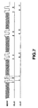
- the upper level latch pulses ULLE produced by timing generator 119 sample the upper amplitude levels of the reference pattern during each repeated block of that reference pattern. Although two samples per block are shown in Fig. 7, it will be appreciated that any desired number of samples may be obtained.
- the lower amplitude levels of the reference pattern are sampled by lower level latch pulses LLLE.
- the latched upper and lover levels of the reference pattern are stored temporarily (as in conventional latch devices) and the stored upper level samples are averaged by averaging circuit 120C while the stored lower level samples are averaged by averaging circuit 120D.
- averaging circuit 120C produces the averaged latched upper level samples u
- averaging circuit 120D produces the averaged latched lower level samples 1 (referred to, for convenience, simply as the averaged upper and lower levels, respectively).
- Calculating circuit 120E operates as an amplitude value calculating circuit to calculate the amplitude control value AMP by averaging the averaged upper and lower levels u and 1.
- Calculating circuit 120F operates as an offset value calculating circuit to calculate the offset control value OFS as a function of the averaged upper and lower levels u and l.
- the amplitude control value AMP produced by amplitude value calculating circuit 120E is fed back via the DSP bus to gain control amplifier 115B, thereby setting the gain of this amplifier as a function of the amplitude control value.
- the offset control value produced by offset value calculating circuit 120F is fed back via the DSP bus to offset control amplifier 115C, thereby setting the offset for this amplifier. It is appreciated that if the distinct amplitude levels of the reference pattern fluctuate, the amplitude and offset control values change in a similar manner, thereby adjusting the gain and offset settings of the gain and offset control amplifiers.
- gain and offset control amplifiers 115B and 115C serve to compensate for such fluctuations.
- the data signals may vary, they are controlled to be well within the dynamic range of A/D converter 116; and as a result, the information read from disk 201 may be accurately sensed, decoded and supplied to computer 300.
- calculating circuits 120E and 120F have been described as operating upon the averaged upper and lover levels detected from four repeated blocks of the reference pattern. It has been further described that the four blocks of the reference pattern are present in the leading portion of a sector of data recorded on disk 201. However, samples of the upper and lower amplitude levels of the reference pattern picked up from several sectors may be averaged such that the calculating circuits operate on averaged levels derived from the reference pattern recorded in a plurality of sectors.
- Fig. 7 illustrates two cycles of the 8T waveform in each block of the reference pattern, with the upper and lower amplitude levels of each cycle being sampled and latched. Although one sample of the . upper amplitude level and one sample of the lower amplitude level for each cycle are shown, it will be appreciated that several samples per cycle may be latched.
Landscapes
- Engineering & Computer Science (AREA)
- Signal Processing (AREA)
- Optical Recording Or Reproduction (AREA)
- Signal Processing For Digital Recording And Reproducing (AREA)
Claims (8)
- Vorrichtung zum Aufzeichnen von Information auf und Wiedergeben von Information von einer magneto-optischen Platte, welche Information, die mit einem magneto-optischen Signal aufgezeichnet wird, in Sektoren als Vertiefungen in einer Spur aufgezeichnet wird, wobei jeder Sektor aus einem Datensegment besteht, in das Servobereiche eingestreut sind, welche Vorrichtung umfasst:Aufzeichnungsmittel (207, 210, 211), die während einer Aufzeichnungsbetriebsart betriebsfähig sind, um zweckdienliche Information und außerdem ein Referenzmuster in einem Sektor aufzuzeichnen, wobei das Referenzmuster in einer Anzahl von Datensegmenten aufgezeichnet wird, die sich in einer anführenden Position jedes Sektors befinden, und das Referenzmuster bestimmte Amplitudenstufen aufweist,einen optischen Kopf (267, 208) zum Auslesen des Referenzmusters und der zweckdienlichen Information aus einer Spur,ein Übertragungsfaktor-Regelungsmittel (115C), dem ein Signal zugeführt wird, das durch den optischen Kopf ausgelesen ist, und das einen einstellbaren Übertragungsfaktor hat, um den Übertragungsfaktor des Signals zu variieren,ein Versatz-Regelungsmittel (115B), dem ein übertragungsfaktorgeregeltes Signal von dem Übertragungsfaktor-Regelungsmittel (115C) zugeführt wird und das einstellbar ist, um den Versatz des übertragungsfaktorgeregelten Signals zu variieren,ein Stufenerfassungsmittel (120A, 120B) zum Erfassen oberer und unterer Amplitudenstufen in dem Referenzmuster, das durch den optischen Kopf ausgelesen ist, undein Berechnungsmittel (120E, 120F), das auf die oberen und unteren Amplitudenstufen anspricht, um Amplituden- und Versatz-Regelungswerte zum Einstellen des Übertragungsfaktors und des Versatzes des Übertragungsfaktor-Regelungsmittels bzw. Versatz-Regelungsmittels zu berechnen, wodurch zweckdienliche Information, die durch den optischen Kopf ausgelesen wird, mit vorbestimmtem Übertragungsfaktor und Versatz wiedergegeben wird.
- Vorrichtung nach Anspruch 1, wobei das Referenzmuster in einer Vielzahl von Blöcken wiederholt wird, wobei jeder Block die oberen und unteren Amplitudenstufen enthält.
- Vorrichtung nach Anspruch 2, wobei jeder Block des Referenzmusters eine erste periodische Wellenform, die eine erste Wiederholungsrate aufweist und die oberen und unteren Amplitudenstufen hat, und eine zweite periodische Wellenform enthält, die eine zweite Wiederholungsrate aufweist, die größer als die erste Wiederholungsrate ist, und die Phasenwechseln unterworfen wird, welche zweite periodische Wellenform erfassbar ist, um einen Takt mit der Drehung der Platte zu synchronisieren.
- Vorrichtung nach Anspruch 3, bei der das Stufenerfassungsmittel ein Abtastmittel, dem Abtastimpulse zugeführt werden, um die oberen und unteren Amplitudenstufen in dem Referenzmuster abzutasten, und ein Zeitsteuermittel umfasst, das mit der Drehung der Platte synchronisiert wird, um die Abtastimpulse zu erzeugen.
- Vorrichtung nach Anspruch 4, bei der das Abtastmittel ein Haltemittel für die obere Stufe zum Halten der abgetasteten oberen Stufe des Referenzmusters und ein Haltemittel für die untere Stufe zum Halten der abgetasteten unteren Stufe des Referenzmusters enthält.
- Vorrichtung nach Anspruch 5, bei der das Referenzmuster in einer Vielzahl von Blöcken wiederholt wird, wobei die Haltemittel für die obere und die untere Stufe die jeweiligen oberen und unteren Stufenabtastproben einer Vielzahl von Blöcken des Referenzmusters halten und wobei das Berechnungsmittel Durchschnittsbildungsmittel für die oberen und unteren Stufen zur Durchschnittsbildung aus den gehaltenen oberen und unteren Stufenabtastproben enthält, aus denen die Amplituden- und Versatz-Regelungswerte gewonnen werden.
- Vorrichtung nach Anspruch 6, bei der das Berechnungsmittel ferner ein Amplituden-Regelungsmittel zum Erzeugen des Amplituden-Regelungswerts durch Bilden eines Durchnitts aus den gemittelten gehaltenen oberen und unteren Stufenabtastproben miteinander umfasst.
- Vorrichtung nach Anspruch 6, bei der das Berechnungsmittel ferner ein Versatz-Regelungsmittel zum Erzeugen des Versatz-Regelungswerts als eine Funktion der Differenz zwischen den gemittelten gehaltenen Abtastproben der oberen und unteren Stufen umfasst.
Applications Claiming Priority (3)
| Application Number | Priority Date | Filing Date | Title |
|---|---|---|---|
| JP25828394 | 1994-10-24 | ||
| JP25828394 | 1994-10-24 | ||
| JP258283/94 | 1994-10-24 |
Publications (3)
| Publication Number | Publication Date |
|---|---|
| EP0709842A2 EP0709842A2 (de) | 1996-05-01 |
| EP0709842A3 EP0709842A3 (de) | 1997-01-02 |
| EP0709842B1 true EP0709842B1 (de) | 2002-09-04 |
Family
ID=17318105
Family Applications (1)
| Application Number | Title | Priority Date | Filing Date |
|---|---|---|---|
| EP95307569A Expired - Lifetime EP0709842B1 (de) | 1994-10-24 | 1995-10-24 | Aufzeichnung und Wiedergabe von Daten |
Country Status (4)
| Country | Link |
|---|---|
| US (1) | US5587975A (de) |
| EP (1) | EP0709842B1 (de) |
| KR (1) | KR960015428A (de) |
| DE (1) | DE69528026D1 (de) |
Families Citing this family (15)
| Publication number | Priority date | Publication date | Assignee | Title |
|---|---|---|---|---|
| EP0726572B1 (de) * | 1994-08-25 | 2002-10-16 | Sony Corporation | Optische platte und optisches plattenantriebsgerät |
| EP0759615A3 (de) * | 1995-08-21 | 1997-11-26 | Nikon Corporation | Plattenförmiges Aufzeichnungsmedium und Wiedergabeeinrichtung |
| US5689479A (en) * | 1995-09-25 | 1997-11-18 | Sony Corporation | Magneto-optical recording apparatus |
| JPH1092037A (ja) * | 1996-09-19 | 1998-04-10 | Canon Inc | 光磁気記録再生方法及び光磁気記録再生装置 |
| US5959280A (en) * | 1997-01-16 | 1999-09-28 | Laser Dynamics, Inc. | Multi-standard optical disk reading apparatus and method of reading using same |
| US20050058039A1 (en) * | 1997-01-16 | 2005-03-17 | Yasuo Kamatani | Multi-standard optical disk and method and apparatus of reading from and recording to the disk |
| DE69841191D1 (de) * | 1997-07-02 | 2009-11-12 | Sharp Kk | Verfahren und Vorrichtung zur Steuerung einer Aufzeichnungsbedingung und optisches Aufzeichnungsmedium für optisches Aufzeichnungsgerät |
| JPH11353732A (ja) * | 1998-06-10 | 1999-12-24 | Canon Inc | 光磁気記録再生方法及び装置 |
| US6401229B1 (en) * | 1998-09-21 | 2002-06-04 | Hewlett-Packard Company | System and method for data error recovery on optical media utilizing hierarchical recovery techniques |
| JP3647681B2 (ja) * | 1999-08-26 | 2005-05-18 | 富士通株式会社 | 情報記憶装置 |
| EP1285438B1 (de) * | 2000-05-16 | 2009-09-30 | Koninklijke Philips Electronics N.V. | Informationsträger und vorrichtungen und methode zum abtasten des informationsträgers |
| JP3496628B2 (ja) * | 2000-05-31 | 2004-02-16 | ヤマハ株式会社 | 光ディスク記録方法および光ディスク記録装置 |
| JP2002184055A (ja) * | 2000-12-08 | 2002-06-28 | Sony Corp | 位相エラー検出装置及び方法、レーザパワー制御装置及び方法、並びに光磁気記録再生装置 |
| WO2003077248A1 (en) * | 2002-03-11 | 2003-09-18 | Matsushita Electric Industrial Co., Ltd. | Signal processing apparatus and signal processing method |
| JP4281391B2 (ja) * | 2003-03-31 | 2009-06-17 | アイシン・エィ・ダブリュ株式会社 | 回転角検出装置及び回転角検出方法 |
Citations (1)
| Publication number | Priority date | Publication date | Assignee | Title |
|---|---|---|---|---|
| EP0430042A2 (de) * | 1989-11-21 | 1991-06-05 | Sony Corporation | Aufzeichnungsmedium und Methode zu dessen Herstellung |
Family Cites Families (12)
| Publication number | Priority date | Publication date | Assignee | Title |
|---|---|---|---|---|
| JPS57200909A (en) * | 1981-06-01 | 1982-12-09 | Victor Co Of Japan Ltd | Reproducing device for information recording medium |
| JPS59257A (ja) * | 1982-06-25 | 1984-01-05 | Pioneer Electronic Corp | デイジタル変調信号読取装置 |
| JPS59116939A (ja) * | 1982-12-23 | 1984-07-06 | Olympus Optical Co Ltd | 光学式記録再生装置 |
| JPS6414772A (en) * | 1987-07-08 | 1989-01-18 | Pioneer Electronic Corp | Rf signal processing circuit |
| US5361247A (en) * | 1989-09-12 | 1994-11-01 | Sharp Kabushiki Kaisha | Information recording and reproducing device with reproduction and automatic gain control circuit |
| JPH04349220A (ja) * | 1991-01-28 | 1992-12-03 | Sony Corp | サンプルサーボ方式の光学ディスク装置 |
| JPH0547111A (ja) * | 1991-08-09 | 1993-02-26 | Sony Corp | 光磁気デイスクのデータ記録再生方式 |
| JP3039029B2 (ja) * | 1991-08-09 | 2000-05-08 | ソニー株式会社 | 光ディスクのデータ記録再生方法 |
| JP3067298B2 (ja) * | 1991-08-09 | 2000-07-17 | ソニー株式会社 | 光ディスクのデータ再生装置と再生方法 |
| US5463603A (en) * | 1992-03-18 | 1995-10-31 | Imp, Inc. | Computer disk drive integrated data path circuit optimized for handling both data and servo signals |
| JP2810592B2 (ja) * | 1992-07-06 | 1998-10-15 | シャープ株式会社 | ディジタル情報再生装置 |
| US5355356A (en) * | 1993-05-19 | 1994-10-11 | Maxoptix Corporation | Charge pump for restoring DC in an optical recording read channel |
-
1995
- 1995-10-20 US US08/545,957 patent/US5587975A/en not_active Expired - Fee Related
- 1995-10-24 KR KR1019950037567A patent/KR960015428A/ko not_active Withdrawn
- 1995-10-24 DE DE69528026T patent/DE69528026D1/de not_active Expired - Lifetime
- 1995-10-24 EP EP95307569A patent/EP0709842B1/de not_active Expired - Lifetime
Patent Citations (1)
| Publication number | Priority date | Publication date | Assignee | Title |
|---|---|---|---|---|
| EP0430042A2 (de) * | 1989-11-21 | 1991-06-05 | Sony Corporation | Aufzeichnungsmedium und Methode zu dessen Herstellung |
Also Published As
| Publication number | Publication date |
|---|---|
| KR960015428A (ko) | 1996-05-22 |
| US5587975A (en) | 1996-12-24 |
| DE69528026D1 (de) | 2002-10-10 |
| EP0709842A3 (de) | 1997-01-02 |
| EP0709842A2 (de) | 1996-05-01 |
Similar Documents
| Publication | Publication Date | Title |
|---|---|---|
| US5761171A (en) | Generating data detecting threshold levels from reference patterns recorded in an optical disk, such as a magneto-optical disk | |
| US5185733A (en) | Calibrating lasers for optical recording using a maximal readback signal amplitude as a criterion | |
| EP0430649B1 (de) | Optisches Scheibengerät mit optimaler Aufzeichnungsvermögenseinstellung | |
| US6385151B2 (en) | Clock signal generating system | |
| US6327240B1 (en) | Optical disc and optical disc drive | |
| EP0709842B1 (de) | Aufzeichnung und Wiedergabe von Daten | |
| US5745457A (en) | Optical disk player with coarse and fine speed control | |
| US5629912A (en) | Focusing servo controlling apparatus | |
| US6842414B1 (en) | Apparatus and method for compensating tilt of optical disc | |
| US6477127B1 (en) | Recording/playback apparatus capable of carrying out linking on optical disk, and optical disk recorded with linked data | |
| EP1008985A2 (de) | Optische Platte | |
| EP0431185B1 (de) | Optischer speicher | |
| JP3039029B2 (ja) | 光ディスクのデータ記録再生方法 | |
| JP3627828B2 (ja) | 光ディスクプレーヤのスピンドルサーボ装置 | |
| JP3067298B2 (ja) | 光ディスクのデータ再生装置と再生方法 | |
| JP3416985B2 (ja) | 光学式ディスク装置 | |
| US5680023A (en) | Method of measuring linear velocity of disk | |
| JPH05258469A (ja) | 光ディスク記録媒体及び記録再生装置の動作制御方法 | |
| US6310843B1 (en) | Clock signal generating system | |
| JP2001229564A (ja) | 光ディスク記録方法及び装置 | |
| JP3507956B2 (ja) | 光ディスク | |
| JP3575099B2 (ja) | 円盤状記録媒体の記録装置及び再生装置 | |
| JPH08180496A (ja) | 光磁気ディスクの記録方法、再生方法及び再生装置 | |
| JP2003099927A (ja) | 光ディスク記録装置 | |
| JP3259299B2 (ja) | 光ディスク及びその記録再生装置 |
Legal Events
| Date | Code | Title | Description |
|---|---|---|---|
| PUAI | Public reference made under article 153(3) epc to a published international application that has entered the european phase |
Free format text: ORIGINAL CODE: 0009012 |
|
| AK | Designated contracting states |
Kind code of ref document: A2 Designated state(s): DE FR GB NL |
|
| PUAL | Search report despatched |
Free format text: ORIGINAL CODE: 0009013 |
|
| AK | Designated contracting states |
Kind code of ref document: A3 Designated state(s): DE FR GB NL |
|
| 17P | Request for examination filed |
Effective date: 19970514 |
|
| 17Q | First examination report despatched |
Effective date: 19990422 |
|
| GRAG | Despatch of communication of intention to grant |
Free format text: ORIGINAL CODE: EPIDOS AGRA |
|
| GRAG | Despatch of communication of intention to grant |
Free format text: ORIGINAL CODE: EPIDOS AGRA |
|
| GRAH | Despatch of communication of intention to grant a patent |
Free format text: ORIGINAL CODE: EPIDOS IGRA |
|
| GRAH | Despatch of communication of intention to grant a patent |
Free format text: ORIGINAL CODE: EPIDOS IGRA |
|
| GRAA | (expected) grant |
Free format text: ORIGINAL CODE: 0009210 |
|
| AK | Designated contracting states |
Kind code of ref document: B1 Designated state(s): DE FR GB NL |
|
| PG25 | Lapsed in a contracting state [announced via postgrant information from national office to epo] |
Ref country code: NL Free format text: LAPSE BECAUSE OF FAILURE TO SUBMIT A TRANSLATION OF THE DESCRIPTION OR TO PAY THE FEE WITHIN THE PRESCRIBED TIME-LIMIT Effective date: 20020904 Ref country code: FR Free format text: LAPSE BECAUSE OF FAILURE TO SUBMIT A TRANSLATION OF THE DESCRIPTION OR TO PAY THE FEE WITHIN THE PRESCRIBED TIME-LIMIT Effective date: 20020904 |
|
| REG | Reference to a national code |
Ref country code: GB Ref legal event code: FG4D |
|
| REF | Corresponds to: |
Ref document number: 69528026 Country of ref document: DE Date of ref document: 20021010 |
|
| PG25 | Lapsed in a contracting state [announced via postgrant information from national office to epo] |
Ref country code: GB Free format text: LAPSE BECAUSE OF NON-PAYMENT OF DUE FEES Effective date: 20021204 |
|
| PG25 | Lapsed in a contracting state [announced via postgrant information from national office to epo] |
Ref country code: DE Free format text: LAPSE BECAUSE OF FAILURE TO SUBMIT A TRANSLATION OF THE DESCRIPTION OR TO PAY THE FEE WITHIN THE PRESCRIBED TIME-LIMIT Effective date: 20021205 |
|
| NLV1 | Nl: lapsed or annulled due to failure to fulfill the requirements of art. 29p and 29m of the patents act | ||
| EN | Fr: translation not filed | ||
| PLBE | No opposition filed within time limit |
Free format text: ORIGINAL CODE: 0009261 |
|
| STAA | Information on the status of an ep patent application or granted ep patent |
Free format text: STATUS: NO OPPOSITION FILED WITHIN TIME LIMIT |
|
| GBPC | Gb: european patent ceased through non-payment of renewal fee | ||
| 26N | No opposition filed |
Effective date: 20030605 |