EP0709976A1 - Optisches Informationsübertragungsnetzwerk mit selbstgenerierenden Sensoren, welche mit Kohärenzmultiplexern verbunden sind - Google Patents
Optisches Informationsübertragungsnetzwerk mit selbstgenerierenden Sensoren, welche mit Kohärenzmultiplexern verbunden sind Download PDFInfo
- Publication number
- EP0709976A1 EP0709976A1 EP95402339A EP95402339A EP0709976A1 EP 0709976 A1 EP0709976 A1 EP 0709976A1 EP 95402339 A EP95402339 A EP 95402339A EP 95402339 A EP95402339 A EP 95402339A EP 0709976 A1 EP0709976 A1 EP 0709976A1
- Authority
- EP
- European Patent Office
- Prior art keywords
- optical
- coherence
- light
- self
- network according
- Prior art date
- Legal status (The legal status is an assumption and is not a legal conclusion. Google has not performed a legal analysis and makes no representation as to the accuracy of the status listed.)
- Ceased
Links
- 230000003287 optical effect Effects 0.000 title claims abstract description 81
- 230000005540 biological transmission Effects 0.000 title description 3
- 230000001934 delay Effects 0.000 claims description 18
- 239000000758 substrate Substances 0.000 claims description 9
- 239000000463 material Substances 0.000 claims description 8
- 239000013078 crystal Substances 0.000 claims description 6
- 230000005520 electrodynamics Effects 0.000 claims description 6
- 238000010521 absorption reaction Methods 0.000 claims description 3
- 210000001520 comb Anatomy 0.000 claims description 3
- 230000008878 coupling Effects 0.000 claims description 3
- 238000010168 coupling process Methods 0.000 claims description 3
- 238000005859 coupling reaction Methods 0.000 claims description 3
- 239000012530 fluid Substances 0.000 claims description 3
- 238000002347 injection Methods 0.000 claims description 2
- 239000007924 injection Substances 0.000 claims description 2
- 230000001902 propagating effect Effects 0.000 claims description 2
- 239000013307 optical fiber Substances 0.000 abstract description 7
- 238000001514 detection method Methods 0.000 abstract description 5
- 230000001427 coherent effect Effects 0.000 abstract 1
- 239000000835 fiber Substances 0.000 abstract 1
- 238000005259 measurement Methods 0.000 description 11
- GQYHUHYESMUTHG-UHFFFAOYSA-N lithium niobate Chemical compound [Li+].[O-][Nb](=O)=O GQYHUHYESMUTHG-UHFFFAOYSA-N 0.000 description 6
- 230000000694 effects Effects 0.000 description 5
- 239000007789 gas Substances 0.000 description 5
- XUIMIQQOPSSXEZ-UHFFFAOYSA-N Silicon Chemical compound [Si] XUIMIQQOPSSXEZ-UHFFFAOYSA-N 0.000 description 4
- 230000008901 benefit Effects 0.000 description 4
- 239000007788 liquid Substances 0.000 description 4
- 238000000034 method Methods 0.000 description 4
- 229910052710 silicon Inorganic materials 0.000 description 4
- 239000010703 silicon Substances 0.000 description 4
- 230000003595 spectral effect Effects 0.000 description 4
- 230000026683 transduction Effects 0.000 description 4
- 238000010361 transduction Methods 0.000 description 4
- 238000005516 engineering process Methods 0.000 description 3
- 239000004065 semiconductor Substances 0.000 description 3
- PEDCQBHIVMGVHV-UHFFFAOYSA-N Glycerine Chemical compound OCC(O)CO PEDCQBHIVMGVHV-UHFFFAOYSA-N 0.000 description 2
- 230000001133 acceleration Effects 0.000 description 2
- 229920000642 polymer Polymers 0.000 description 2
- 239000000126 substance Substances 0.000 description 2
- 229910001218 Gallium arsenide Inorganic materials 0.000 description 1
- 238000009792 diffusion process Methods 0.000 description 1
- 238000010292 electrical insulation Methods 0.000 description 1
- 230000007613 environmental effect Effects 0.000 description 1
- 238000001914 filtration Methods 0.000 description 1
- 238000009434 installation Methods 0.000 description 1
- 238000012423 maintenance Methods 0.000 description 1
- 238000004377 microelectronic Methods 0.000 description 1
- 239000000203 mixture Substances 0.000 description 1
- 230000006855 networking Effects 0.000 description 1
- 229920000620 organic polymer Polymers 0.000 description 1
- 230000010287 polarization Effects 0.000 description 1
- 230000009467 reduction Effects 0.000 description 1
- 230000008054 signal transmission Effects 0.000 description 1
- 230000001629 suppression Effects 0.000 description 1
Images

Classifications
-
- H—ELECTRICITY
- H04—ELECTRIC COMMUNICATION TECHNIQUE
- H04J—MULTIPLEX COMMUNICATION
- H04J14/00—Optical multiplex systems
- H04J14/08—Time-division multiplex systems
-
- H—ELECTRICITY
- H04—ELECTRIC COMMUNICATION TECHNIQUE
- H04J—MULTIPLEX COMMUNICATION
- H04J14/00—Optical multiplex systems
- H04J14/002—Coherencemultiplexing
Definitions
- the present invention relates to an information transmission network in optical form.
- Multisensor networks are used more and more in the automotive industry, in home automation, in aeronautics, in shipbuilding and in environmental control in hostile or non-hostile environments.
- the data is then transported by an electric cable.
- An electrical type multiplexing requires a certain number of external cables, intended for the power supply or for the installation of individual electrical power supplies for each of the sensors of the network.
- the object of the present invention is to remedy the above drawbacks.
- the output signals of a set of self-generating sensors are transformed and multiplexed into optical information capable of being transported by an optical line or "optical bus", to demultiplexing means constituting a single measurement center.
- the latter allows remote interrogation of each of the network's sensors.
- Self-generating sensors are widely used as force, pressure, speed or acceleration sensors, due to their reliability and low cost.
- the present invention makes it possible to associate on the same optical bus self-generating sensors for different types, which are for example suitable for measurements of pressure, temperature, speed, acceleration, force or chemical composition of gases.
- the present invention also makes it possible to take advantage of the integrated optics on lithium niobate or on a semiconductor such as for example silicon or else on electro-optical materials such as certain polymers, to effect the transduction of optical or electrical data generated by auto-generating sensors in the form of optically multiplexable data on an optical line, without external energy supply.
- self-generating sensors are associated with coherence multiplexers directly supplied by the electrical signals supplied by these sensors.
- At least one of the self-generating sensors can be a piezoelectric type or electro-dynamic type sensor.
- Piezoelectric sensors behave like generators of electric charges while electro-dynamic sensors behave like generators of voltage.
- the coherence multiplexers used in the invention can be integrated modulators which introduce optical delays greater than the coherence length of the network light source.
- the advantage of the invention compared to an electrical multiplexing resides in the fact of being free from any external electrical supply and therefore of reducing the wiring problems.
- the coherence multiplexing method is known for the transmission of signals or for the networking of interferometric optical sensors.
- Document (2) also discloses coherence modulators using the technology of integrated optics.
- the present invention combines, in an original way, the coherence multiplexing method with the use of self-generating sensors, for example of the electro-dynamic type or of the piezoelectric type.
- any optical means can be used, the operation of which is reduced to that of a tunable spectral filter or of an interferometer set to a optical delay greater than the coherence length of the light source and such that no modulation of the output light intensity appears under the effect of the tuning of the filter or the interferometer.
- the multiplexing means and the demultiplexing means used in the present invention can for example be two-wave interferometers or multiple wave interferometers, optical loops, directional couplers or electro-optical or acousto-optical or magneto- modulators optical or piezo-optical or elasto-optical or other means involving electrical, acoustic, magnetic or mechanical effects to induce and modulate delays greater than the coherence length of the light source or to induce spectral filtering of the lengths wave.
- This coding operation is carried out by each of the multiplexers which introduce, on the light which passes through them, optical delays D different from each other but all greater than the coherence length of the source.
- the light wave trains emitted by this source are thus placed in a non-interference situation since the optical delays involved are greater than the coherence length of the source.
- the coherence multiplexing means can be mounted in series or in parallel or both in series and in parallel on the optical line.
- the light source used can operate in continuous mode (i.e. emit light of constant intensity over time) or operate in pulse mode (i.e. emit light in the form of pulses bright).
- the light emitted by this source can be modulated before injection into the optical line so that the optical carrier is also modulated, for example in phase or in wavelength or in polarization.
- the coherence demultiplexing means used in the invention introduce optical delays equivalent to those used in the multiplexing means.
- At least one of the coherence multiplexing means and the self-generating sensor associated with it can be integrated in the same component.
- This component may include a Mach-Zehnder interferometer whose arms are asymmetrical so as to introduce an optical delay greater than the coherence length of the light source, one of the arms of the interferometer being covered with a layer capable of modify the passage of light in the arm it covers.
- This layer can be made of a material whose optical properties are modified by absorption of molecules from a fluid.
- this layer can be made of a piezoelectric material.
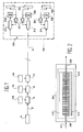
- the network according to the invention which is schematically represented in FIG. 1, comprises an optical line constituted by an optical fiber 2.
- This network also includes a light source 4, the light of which is injected into one end of the optical fiber 2.
- This source 4 has a short coherence length and can for example be a superluminescent diode or a light emitting diode with a wavelength of 850 nm and a coherence length of 40 ⁇ m.
- This diode can operate in continuous or pulse mode.
- the network of FIG. 1 also includes coherence multiplexers 6, 8 and 10 which are inserted in the optical line.
- These coherence multiplexers are mounted in series on this optical line and are respectively connected to self-generating sensors 12, 14 and 16.
- the coherence multiplexers 6, 8 and 10 are provided for converting the signals supplied by the sensors into optical form, by modulating the coherence of these signals, and for multiplexing the light information thus obtained.
- a central measurement unit 18 comprising means for demultiplexing the signals.
- the optical fiber 2 can be single-mode or multi-mode depending on the type of technology chosen for the measurement unit 18.
- the self-generating sensors are piezoelectric sensors.
- Each of them comprises for example a silicon beam on which a piezoelectric material is deposited.
- the electrical data supplied by these sensors 12, 14 and 16 are respectively applied to the multiplexers 6, 8 and 10.
- Each of the sensors provides, for example, a few pC with an output impedance of the order of 80 M ⁇ .
- the multiplexers 6, 8 and 10 split the light wave trains emitted by the source 4 and respectively introduce optical delays D1, D2 and D3 which are greater than the coherence length of this source 4.
- the light emitted by the source undergoes these predetermined optical delays, which can be modulated by the electrical signals generated by the sensors.
- the electrical data from each of the piezoelectric sensors 12, 14 and 16 are directly coded in the form of optical delays.
- This electro-optical data transduction takes place directly, that is to say without an impedance transformer, when the input impedance of the optical multiplexers is greater than the output impedance of the sensors.
- the output impedance of the piezoelectric sensors can be very high, for example equal to 50 M ⁇ .
- each sensor usually requires, at the output of each sensor, an impedance transformer ensuring a reduction in the output impedance to make it compatible with the input impedance of the electronic measurement or multiplexing circuits, which is generally 50 ⁇ or 75 ⁇ .
- This impedance transformer generally includes operational amplifiers which require an external power supply.
- An advantage provided by the present invention is that it makes it possible to produce a network of multisensors while avoiding the use of such impedance transformers and therefore the use of any external electrical energy source.
- the invention therefore makes it possible to take full advantage of the self-generating nature of the sensors.
- the multiplexers 6, 8 and 10 are for example electro-optical multiplexers integrated on a lithium niobate substrate, with an input impedance of 150 M ⁇ and a control voltage of the order of 5 to 10 volts.
- lithium niobate can be used, for example organic polymers, silicon or other semiconductor materials.
- Multiplexers 6, 8 and 10 have both an impedance matching function and an optical multiplexing function.
- the electrical charges (typically of the order of a few pC) supplied by each of the sensors 12, 14 and 16 are coded in the form of a succession of optical delays greater than the coherence length of the source 4 so that no modulation of light intensity is not detectable at the output of all the multiplexers 6, 8 and 10.
- the light reaches the central measurement unit 18 after having traversed the optical fiber 2.
- This central measurement unit 18 comprises demultiplexing means 20, 22 and 24 which receive as input the light transmitted by the optical fiber 2, via an optical coupler 26 at one input and a number of outputs equal to the number of demultiplexing means.
- the latter are respectively associated with the multiplexing means 6, 8 and 10 and are constituted by means which apply optical delays and are respectively tuned on the optical delays corresponding to the sensors 12, 14 and 16.
- demultiplexing means can be produced from the same components as those which are used to form the multiplexing means 6, 8 and 10.
- the optical delay chords are made and controlled automatically by means of feedback loops.
- each of the demultiplexing means or demultiplexers 20, 22 and 24 is associated with a photodetector 28 which receives as input the light coming from the corresponding demultiplexer.
- a servo loop 30 uses the signal detected by this photodetector 28 to control the corresponding demultiplexer in order to obtain a maximum signal at the output of this photodetector.
- Each photodetector 28 is also provided with a means 32 for displaying the data 32 detected by this photodetector.
- D represents the value of the lowest optical delay to be introduced and depends on the crosstalk rate which it is desired to obtain between the different sensors .
- a delay D equal to 84 ⁇ m is chosen for a crosstalk rate of -30 dB optical.
- FIG. 2 An example of a coherence multiplexer which can be used in the present invention is shown diagrammatically in FIG. 2.
- This coherence multiplexer comprises a substrate 36 made of a birefringent electro-optical crystal, for example a crystal of lithium niobate.
- An optical guide 38 is formed by diffusion in this substrate 36.
- the multiplexer of FIG. 2 also includes electrodes which are formed by interdigital combs 40.
- the latter introduce a coupling between the transverse electrical propagation mode TE and the transverse magnetic propagation mode TM of the light 41 which propagates in the guide 38.
- the distance between two fingers of the electrodes is 4 ⁇ m and the guide 38 has a width of 5 mm.
- This optical delay is modulated by the electrical charges provided for example by a piezoelectric micro-sensor not shown, the terminals of which are connected to the electrodes 40, which makes it possible to directly transform the electrical signal of this micro-sensor into an optical signal modulated in coherence.
- a crystal cut is used which makes it possible to obtain both greater optical delay the coherence length of the light source and significant electrical insulation between the electrodes.
- a section ensuring the propagation of light along the crystallographic axis Z makes it possible to obtain a coherence modulator having an input impedance of several hundred megohms because the leakage currents are then very low .
- Such a method can also be associated with other configurations of coherence multiplexers such as those described in document (13) as well as in document (2).
- FIG. 3 schematically represents another coherence multiplexer usable in the present invention and adapted to the detection of a fluid (gas or liquid).
- This multiplexer is produced by means of a Mach-Zehnder interferometer 44 whose arms 46 and 48 are very asymmetrical so as to introduce an optical delay greater than the coherence length of the light source (not shown) with which it is used .
- the arm 46 of the interferometer is covered with a layer 50, for example a layer of polymer, the optical properties of which are modified by absorption of the molecules of the liquid or of the gas.
- the component of FIG. 3 behaves both as a gas or liquid or force detector and as a coherence multiplexer, this without any external electrical energy supply.
- the various types of sensors can be put in any order to form a network of optically multiplexed multisensors.
- FIG. 4 schematically represents an exemplary embodiment in which the sensors are arranged in a series-parallel architecture.
- light sources 52, 54 and 56 of short coherence length supply elementary optical lines 58, 60 and 62 respectively.
- Coherence multiplexers 68 and 70 are connected in series on line 58, other coherence multiplexers 72, 74 are connected in series on line 60 and other coherence multiplexers 76 and 78 are connected in series on line 62.
- Each of these coherence multiplexers is connected to a self-generating sensor, not shown.
- the three lines 58, 60 and 62 are mounted in parallel and are connected to a main line 80 via an optical coupler 82.
- the main optical line 80 makes it possible to connect the elementary optical lines 58, 60 and 62 to a measurement center 84.
- All the signals from the sensors are transformed, using the multiplexers 68 to 78, into coherently modulated optical signals and are then routed by the main optical line 80 (optical bus) to the measurement center 84.
- This central measurement unit comprises demultiplexing means (not shown), of the type of those which have been mentioned previously, for interrogating each of the self-generating sensors.
Landscapes
- Engineering & Computer Science (AREA)
- Computer Networks & Wireless Communication (AREA)
- Signal Processing (AREA)
- Arrangements For Transmission Of Measured Signals (AREA)
Applications Claiming Priority (2)
| Application Number | Priority Date | Filing Date | Title |
|---|---|---|---|
| FR9412677A FR2726140B1 (fr) | 1994-10-24 | 1994-10-24 | Reseau de transmission d'informations sous forme optique, a capteurs auto-generateurs associes a des multiplexeurs de coherence |
| FR9412677 | 1994-10-24 |
Publications (1)
| Publication Number | Publication Date |
|---|---|
| EP0709976A1 true EP0709976A1 (de) | 1996-05-01 |
Family
ID=9468135
Family Applications (1)
| Application Number | Title | Priority Date | Filing Date |
|---|---|---|---|
| EP95402339A Ceased EP0709976A1 (de) | 1994-10-24 | 1995-10-20 | Optisches Informationsübertragungsnetzwerk mit selbstgenerierenden Sensoren, welche mit Kohärenzmultiplexern verbunden sind |
Country Status (2)
| Country | Link |
|---|---|
| EP (1) | EP0709976A1 (de) |
| FR (1) | FR2726140B1 (de) |
Citations (4)
| Publication number | Priority date | Publication date | Assignee | Title |
|---|---|---|---|---|
| US4748686A (en) * | 1986-10-15 | 1988-05-31 | United Technologies Corporation | Coherence multiplexed optical position transducer |
| US4866698A (en) * | 1987-11-17 | 1989-09-12 | The Boeing Company | Multiplexed optical communication system |
| US4956834A (en) * | 1989-01-12 | 1990-09-11 | The Boeing Company | Coherence multiplexed optical signal transmission system and method |
| EP0526286A1 (de) * | 1991-07-30 | 1993-02-03 | Thomson-Csf | Verfahren zur Übertragung über Lichtleitfaser von einem Signal aus einem Sensor, insbesondere aus einem Wasserschalwandler |
-
1994
- 1994-10-24 FR FR9412677A patent/FR2726140B1/fr not_active Expired - Fee Related
-
1995
- 1995-10-20 EP EP95402339A patent/EP0709976A1/de not_active Ceased
Patent Citations (4)
| Publication number | Priority date | Publication date | Assignee | Title |
|---|---|---|---|---|
| US4748686A (en) * | 1986-10-15 | 1988-05-31 | United Technologies Corporation | Coherence multiplexed optical position transducer |
| US4866698A (en) * | 1987-11-17 | 1989-09-12 | The Boeing Company | Multiplexed optical communication system |
| US4956834A (en) * | 1989-01-12 | 1990-09-11 | The Boeing Company | Coherence multiplexed optical signal transmission system and method |
| EP0526286A1 (de) * | 1991-07-30 | 1993-02-03 | Thomson-Csf | Verfahren zur Übertragung über Lichtleitfaser von einem Signal aus einem Sensor, insbesondere aus einem Wasserschalwandler |
Non-Patent Citations (2)
| Title |
|---|
| KERSEY A D ET AL: "DISTRIBUTED AND MULTIPLEXED FIBRE-OPTIC SENSOR SYSTEMS", JOURNAL OF THE INSTITUTION OF ELECTRONIC AND RADIO ENGINEERS, LONDON, GB, vol. 58, no. 5, SUPPLEMENT, pages S99 - S111, XP000002678 * |
| X. ZHOU ET AL: "Detection Scheme of Coherence-Multiplexed Sensor Signals Using an Optical Loop with a Frequency Shifter : Sensitivity Enhancement", IEEE PHOTONICS TECHNOLOGY LETTERS, vol. 6, no. 6, NEW YORK US, pages 767 - 769, XP000457243 * |
Also Published As
| Publication number | Publication date |
|---|---|
| FR2726140A1 (fr) | 1996-04-26 |
| FR2726140B1 (fr) | 1996-11-22 |
Similar Documents
| Publication | Publication Date | Title |
|---|---|---|
| EP0975107B1 (de) | Sendevorrichtung für optische Daten | |
| EP2307856B1 (de) | Glasfasersensor mit selbstreferenz mit stimulierter brillouin-streuung | |
| FR2761490A1 (fr) | Circuit de detection de positions d'impulsions optiques, appareil de production d'impulsions optiques et procedes pour leur utilisation | |
| EP3903441A1 (de) | Verfahren und vorrichtung zur an einen quantenserver delegierten quantenberechnung von einem client zur erzeugung eines quantenzustands, der dem client bekannt ist, aber vom quantenserver verborgen ist | |
| US20090111417A1 (en) | Adaptive mixing for high slew rates | |
| FR2580072A1 (de) | ||
| WO2001035062A2 (en) | Optical method for the transmission of signals from remote arrays of electrical sensors | |
| FR2772150A1 (fr) | Modulateur optique utilisant un isolateur et transmetteur optique comprenant le susdit | |
| EP3243042A1 (de) | Faseroptischer sensor | |
| Li et al. | Demodulation of fiber Bragg grating accelerometer using in-line Sagnac interferometers | |
| WO2022122594A1 (fr) | Dispositif d'analyse spectrale large bande d'un signal d'intérêt | |
| EP0716486B1 (de) | Wellenlängenkonverter | |
| EP0206901A1 (de) | Anordnung zur Steuerung und Überwachung einer industriellen Anlage durch optische Übertragung von Nachrichten und Befehlen | |
| EP3071938B1 (de) | Sensor mit hochempfindlicher glasfaser | |
| EP0709976A1 (de) | Optisches Informationsübertragungsnetzwerk mit selbstgenerierenden Sensoren, welche mit Kohärenzmultiplexern verbunden sind | |
| EP0671791B1 (de) | Elektrooptischer Halbleitermodulator und optisches Transmissionssystem unter Verwendung dieses Modulators | |
| EP4073472B1 (de) | Vorrichtung zum messen von signalen, die von einem netzwerk von faseroptischen laserresonatorsensoren bereitgestellt werden | |
| EP3200363B1 (de) | System zur linearen optischen abtastung und kohärenten erkennung eines optischen signals | |
| EP0522967B1 (de) | Faseroptisches Gyrometer für Navigations- und Stabilisierungszentrum | |
| EP0421880B1 (de) | Polyvalentes integriertes optisches Bauteil und Verteilungsnetz mit optischer Verstärkung | |
| FR2703451A1 (fr) | Dispositif de mesure interférométrique en lumière polarisée. | |
| FR2608869A1 (fr) | Systeme de multiplexage et de demultiplexage faisant intervenir des retards optiques, pour la transmission de signaux sur fibre optique | |
| EP0290297B1 (de) | Sperrfilter für optische Signale und seine Anwendung in Ringinterferometern | |
| EP0525162B1 (de) | Sequentielle demultiplexierungsempfänger für spektralmodulationskodiertes sensornetzwerk | |
| FR3155994A1 (fr) | Procede et dispositif de communication-bidirectionnelle sur une seule fibre optique avec une seule source de lumiere |
Legal Events
| Date | Code | Title | Description |
|---|---|---|---|
| PUAI | Public reference made under article 153(3) epc to a published international application that has entered the european phase |
Free format text: ORIGINAL CODE: 0009012 |
|
| AK | Designated contracting states |
Kind code of ref document: A1 Designated state(s): CH DE GB LI |
|
| 17P | Request for examination filed |
Effective date: 19961004 |
|
| 17Q | First examination report despatched |
Effective date: 20010223 |
|
| APAB | Appeal dossier modified |
Free format text: ORIGINAL CODE: EPIDOS NOAPE |
|
| APAB | Appeal dossier modified |
Free format text: ORIGINAL CODE: EPIDOS NOAPE |
|
| APAD | Appeal reference recorded |
Free format text: ORIGINAL CODE: EPIDOS REFNE |
|
| APBX | Invitation to file observations in appeal sent |
Free format text: ORIGINAL CODE: EPIDOSNOBA2E |
|
| APAF | Appeal reference modified |
Free format text: ORIGINAL CODE: EPIDOSCREFNE |
|
| APBT | Appeal procedure closed |
Free format text: ORIGINAL CODE: EPIDOSNNOA9E |
|
| 18R | Application refused |
Effective date: 20061026 |
|
| STAA | Information on the status of an ep patent application or granted ep patent |
Free format text: STATUS: THE APPLICATION HAS BEEN REFUSED |
|
| R18R | Application refused (corrected) |
Effective date: 20061231 |