EP0710001B1 - Filtre en logique floue pour des images dans du bruit d'impulsions - Google Patents
Filtre en logique floue pour des images dans du bruit d'impulsions Download PDFInfo
- Publication number
- EP0710001B1 EP0710001B1 EP94830521A EP94830521A EP0710001B1 EP 0710001 B1 EP0710001 B1 EP 0710001B1 EP 94830521 A EP94830521 A EP 94830521A EP 94830521 A EP94830521 A EP 94830521A EP 0710001 B1 EP0710001 B1 EP 0710001B1
- Authority
- EP
- European Patent Office
- Prior art keywords
- filter
- accordance
- digital
- output
- block
- Prior art date
- Legal status (The legal status is an assumption and is not a legal conclusion. Google has not performed a legal analysis and makes no representation as to the accuracy of the status listed.)
- Expired - Lifetime
Links
Images


Classifications
-
- G—PHYSICS
- G06—COMPUTING OR CALCULATING; COUNTING
- G06T—IMAGE DATA PROCESSING OR GENERATION, IN GENERAL
- G06T5/00—Image enhancement or restoration
- G06T5/20—Image enhancement or restoration using local operators
-
- H—ELECTRICITY
- H03—ELECTRONIC CIRCUITRY
- H03H—IMPEDANCE NETWORKS, e.g. RESONANT CIRCUITS; RESONATORS
- H03H2222/00—Indexing scheme relating to digital filtering methods
- H03H2222/02—Indexing scheme relating to digital filtering methods using fuzzy logic
Definitions
- the present invention relates to an electronic device used in video applications and specifically to a filter performing on video images a reduction of the pulsed noise in accordance with fuzzy logic.
- the present invention also relates to a method for performing on video images a reduction of the pulsed noise in accordance with fuzzy logic.
- a typical noise present in video signals is the pulsed noise. Its effects are such as to change the grey level of a so-called image pixel so as to cause a peak of luminosity (positive or negative) to appear in a nearly homogeneous image region.
- the technical problem underlying the present invention is to provide a filter and associated filtering method for performing a reduction of the pulsed noise contained in video images in accordance with fuzzy logic which would be structurally very simple while achieving high quality of the filtered image.
- the number 1 indicates schematically as a whole a filter provided in accordance with the present invention to secure reduction of the pulsed noise on video images and in accordance with a fuzzy logic procedure.
- image field is defined as a group of lines constituting a video image in the same time interval.
- the filter 1 has at least three input terminals designed to receive digital signals for image lines consecutive in time CF_PPL, CF_PL, CF_CL of a current image field.
- the filter 1 comprises an interface circuit 2 having a first, a second and a third input terminal coinciding with the input terminals of the filter 1, and a plurality of output terminals.
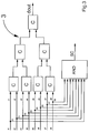
- FIG. 2 shows in greater detail the internal structure of the interface circuit 2.
- It comprises a plurality of delay blocks T which allow delaying appropriately the digital signals present at the inputs of the filter 1 so as to create a working window or image window shown in FIG. 2A.
- this window comprises nine digital signals.
- the digital signals included in the central line belong to the image line CF_PL while the digital signals included in the first and last lines belong to the image lines CF_PPL and CF_CL.
- the digital signal X in which the work signal is centred is the signal to be processed.
- SDi digital subtractors
- the first input terminals of the digital subtractors SDi are designed to receive the digital signal X to be processed while each of the second input terminals of said subtractors receives one of the remaining digital signals included in the image window.
- each of the signals di represent the difference between the grey level associated with the image pixel to be processed and the grey level associated with an image pixel adjacent thereto.
- a pixel is considered affected by pulsed noise if its grey level is totally different from the grey level of the pixels adjacent thereto.
- the filter 1 also comprises a comparator block 3 whose internal structure is shown in FIG. 3 which has a plurality of input terminals designed to receive the difference signals di and a first and a second output terminal.
- This comparator block 3 is designed to perform on said difference signals di subsequent comparisons by means of a plurality of comparator sub-blocks C connected together in cascade.
- the first output terminal of block 3 receives a difference signal dout coinciding with that between the difference signals di which has minimum modulus value.
- the difference signals di are coded with six bits of which the most (or least) significant represents the sign.
- Said logic circuit L is provided essentially through an AND logic port with eight inputs and is designed to generate a control signal SC which is received from the second output terminal of block 3.
- the signal SC can assume the logic values 0 or 1.
- the filter 1 comprises a memory circuit 4 having a first input terminal connected to the first output terminal dout of the comparator block 3 and of an output terminal.
- the circuit 4 also has an enablement input designed to receive the control signal SC present at the output of the logic circuit L.
- control signal SC assumes value 0, i.e. the difference signals di do not all exhibit the same sign, the pixel being processed is surely not affected by pulsed noise because its grey level is not totally different from the grey levels of the adjacent pixels.
- the pixel being processed is not filtered.
- control signal SC assumes value 1 the pixel being processed may or may not be affected by pulsed noise.
- the memory circuit 4 comprises a plurality of memory elements addressed through the value of dout and designed for memorising the results achieved by executing off-line a fuzzy procedure, which is described below, to appraise in what measure the pixel being processed is affected or not by pulsed noise.
- Said results represent the values, inside the interval [0,1], taken on by a Knoise parameter which is representative of the quantity of pulsed noise present in the pixel being processed.
- the structure of the filter 1 also comprises an arithmetic block 5 having a first, a second and a third input terminal and an output terminal coinciding with an output terminal of the filter 1.
- a filtering circuit F having a first, a second and a third input terminal and an output terminal.
- the first input terminal of the arithmetic block 5 is connected to the output terminal of the memory circuit 4 while the second and third input terminals of said block are connected to the third input terminal and the output terminal respectively of the filtering circuit F.
- the input terminals of the circuit F are connected to output terminals of the interface circuit 2 so as to receive the digital signals P7, P2 and X respectively situated along a column of the image window.
- the filtering circuit F whose embodiment calls for the employment of a vertical median filter with three points of the conventional type is designed to organize the values of the signals present at its inputs and supply at output a value indicated by M.
- the filtering method is essentially structured in accordance with two successive steps.
- the filter 1 through the formula (1) implemented by the arithmetic block 5 performs a soft switch between the original digital signal X representing the grey level associated with the pixel being processed and the output M of the filtering circuit F.
- each rule includes at least eight antecedent prepositions each represented by a difference signal di calculated through the digital subtractors SDi.
- Calculation of the antecedent part of the fuzzy rules through the comparator block 3 produces as a result a value for the digital signal dout.
Landscapes
- Physics & Mathematics (AREA)
- General Physics & Mathematics (AREA)
- Engineering & Computer Science (AREA)
- Theoretical Computer Science (AREA)
- Picture Signal Circuits (AREA)
- Image Processing (AREA)
Claims (9)
- Filtre à logique floue pour effectuer une réduction de bruit impulsionnel sur des images vidéo, comprenant:au moins un circuit d'interface (2) recevant en entrée des signaux numériques consécutifs dans le temps et correspondant auxdites images vidéo et servant à générer une fenêtre d'image centrée sur un signal numérique (X) à traiter,au moins un bloc comparateur (3) ayant une pluralité de bornes d'entrée couplées avec des bornes de sortie du circuit d'interface (2) par l'intermédiaire d'une pluralité de soustracteurs (SDi),au moins un circuit de mémoire (4) connecté en cascade avec le bloc comparateur (3) et comprenant une pluralité d'éléments mémoire servant à stocker des valeurs d'un paramètre (Knoise) obtenu par une procédure effectuée au moyen de procédures de logique floue sur la base des sorties du bloc comparateur (3),au moins un circuit de filtrage (F) ayant des entrées connectées à quelques sorties du circuit d'interface (2) et servant à organiser les valeurs desdites entrées,au moins un bloc arithmétique (5) ayant une première borne d'entrée connectée à une borne de sortie du circuit mémoire (4) et une seconde borne d'entrée servant à recevoir le signal numérique (X) à traiter et une troisième entrée connectée à une borne de sortie du circuit de filtrage (F) et ledit bloc arithmétique (5) étant destiné à effectuer une commutation entre le signal numérique (X) à traiter et la sortie du circuit de filtrage (F) sur la base des valeurs prises par le paramètre (Knoise).
- Filtre selon la revendication 1 caractérisé en ce que le bloc comparateur (3) comprend une pluralité de sous-blocs comparateurs (C) dont quelques uns sont connectés en sortie aux soustracteurs numériques (SDi) et le reste sont connectés ensemble en cascade et qui servent à effectuer des comparaisons ultérieures sur des signaux différentiels (di), calculés par les soustracteurs numériques (SDi), pour générer un signal différentiel (dout) ayant une amplitude minimale.
- Filtre selon la revendication 2 caractérisé en ce que le bloc comparateur (3) comprend un bloc logique (L) ayant une pluralité de bornes d'entrée chacune connectée à la sortie d'un soustracteur numérique (SDi) correspondant pour recevoir des signaux numériques (Si) représentant le bit de signe des signaux différentiels (di) et ledit bloc logique (L) étant destiné à générer un signal de commande (SC).
- Filtre selon la revendication 3 caractérisé en ce que ledit signal de commande (SC) est reçu par une entrée de mise en service du circuit mémoire (4).
- Filtre selon la revendication 3 caractérisé en ce que ledit bloc logique (L) est obtenue au moyen d'une porte logique ET.
- Filtre selon la revendication 4 caractérisé en ce que la pluralité d'éléments mémoire contenus dans le circuit mémoire (4) sont adressés par le signal numérique (dout) délivré en sortie par le bloc comparateur (3).
- Procédé de filtrage du bruit impulsionnel présent dans les images vidéo pour lequel est définie une fenêtre d'image centrée sur un signal numérique (X) à traiter par un circuit d'interface (2) et ledit signal numérique (X) à traiter étant filtré dans un circuit de filtrage (F) comprenant au moins les étapes suivantes:détecter sur la base de procédures de logique floue des valeurs de paramètre (Knoise) destinées à être utilisées dans un bloc arithmétique d'interpolation (5), etcommuter sur la base des valeurs du paramètre (Knoise) entre un signal numérique (X) à traiter et la sortie du circuit de filtrage (F).
- Procédé selon la revendication 7 caractérisé en ce que l'étape de détection comprend une comparaison entre un signal numérique (X) à traiter et d'autres signaux numériques contenus dans la fenêtre d'image obtenue au moyen du circuit d'interface (2).
- Procédé selon la revendication 8, caractérisé en ce que ladite comparaison est effectuée par un bloc comparateur (3) ayant une pluralité de bornes d'entrée couplées avec des bornes de sortie du circuit d'interface (2) par l'intermédiaire d'une pluralité de soustracteurs (SDi).
Priority Applications (4)
| Application Number | Priority Date | Filing Date | Title |
|---|---|---|---|
| DE69417236T DE69417236T2 (de) | 1994-10-31 | 1994-10-31 | Fuzzy-Logikfilter für Bilder mit Impulsrauschen |
| EP94830521A EP0710001B1 (fr) | 1994-10-31 | 1994-10-31 | Filtre en logique floue pour des images dans du bruit d'impulsions |
| US08/558,596 US6034741A (en) | 1994-10-31 | 1995-10-30 | Fuzzy logic filter for impulsive noisy images |
| JP7283369A JPH08275031A (ja) | 1994-10-31 | 1995-10-31 | ビデオ画像のパルス化雑音低減用フィルタ |
Applications Claiming Priority (1)
| Application Number | Priority Date | Filing Date | Title |
|---|---|---|---|
| EP94830521A EP0710001B1 (fr) | 1994-10-31 | 1994-10-31 | Filtre en logique floue pour des images dans du bruit d'impulsions |
Publications (2)
| Publication Number | Publication Date |
|---|---|
| EP0710001A1 EP0710001A1 (fr) | 1996-05-01 |
| EP0710001B1 true EP0710001B1 (fr) | 1999-03-17 |
Family
ID=8218569
Family Applications (1)
| Application Number | Title | Priority Date | Filing Date |
|---|---|---|---|
| EP94830521A Expired - Lifetime EP0710001B1 (fr) | 1994-10-31 | 1994-10-31 | Filtre en logique floue pour des images dans du bruit d'impulsions |
Country Status (4)
| Country | Link |
|---|---|
| US (1) | US6034741A (fr) |
| EP (1) | EP0710001B1 (fr) |
| JP (1) | JPH08275031A (fr) |
| DE (1) | DE69417236T2 (fr) |
Cited By (1)
| Publication number | Priority date | Publication date | Assignee | Title |
|---|---|---|---|---|
| CZ304181B6 (cs) * | 2009-02-16 | 2013-12-11 | Vysoké ucení technické v Brne, Fakulta informacních technologií | Nelineární obrazový filtr |
Families Citing this family (3)
| Publication number | Priority date | Publication date | Assignee | Title |
|---|---|---|---|---|
| DE69623253D1 (de) * | 1996-03-07 | 2002-10-02 | St Microelectronics Srl | Verarbeitungsanordnung für Videosignale |
| KR100446723B1 (ko) * | 1997-10-23 | 2004-11-16 | 엘지전자 주식회사 | 그레이 영상의 잡음 제거방법 |
| JP5120441B2 (ja) * | 2009-11-26 | 2013-01-16 | 株式会社ニコン | 画像処理装置 |
Family Cites Families (6)
| Publication number | Priority date | Publication date | Assignee | Title |
|---|---|---|---|---|
| DE69032318T2 (de) * | 1989-08-31 | 1998-09-24 | Canon Kk | Vorrichtung zur Bildverarbeitung |
| JPH04294466A (ja) * | 1991-03-22 | 1992-10-19 | Ricoh Co Ltd | 画像処理装置 |
| JPH0591532A (ja) * | 1991-09-30 | 1993-04-09 | Toshiba Corp | 画像フイルタ、適応型画像フイルタの学習方法 |
| JPH0594523A (ja) * | 1991-10-01 | 1993-04-16 | Yokogawa Medical Syst Ltd | 画像処理方法および画像処理装置 |
| EP0655711B1 (fr) * | 1993-11-30 | 2000-03-29 | STMicroelectronics S.r.l. | Filtre pour traiter des signaux numériques d'image pour des appareils vidéo |
| EP0680224B1 (fr) * | 1994-04-27 | 2002-11-13 | Co.Ri.M.Me. Consorzio Per La Ricerca Sulla Microelettronica Nel Mezzogiorno | Filtrage réducteur de bruit et convertissage interpolant de taux de balayage pour signaux vidéo numériques, contrôlés par information sur la correlation entre-trame obtenue par la logique floue |
-
1994
- 1994-10-31 EP EP94830521A patent/EP0710001B1/fr not_active Expired - Lifetime
- 1994-10-31 DE DE69417236T patent/DE69417236T2/de not_active Expired - Fee Related
-
1995
- 1995-10-30 US US08/558,596 patent/US6034741A/en not_active Expired - Lifetime
- 1995-10-31 JP JP7283369A patent/JPH08275031A/ja active Pending
Cited By (1)
| Publication number | Priority date | Publication date | Assignee | Title |
|---|---|---|---|---|
| CZ304181B6 (cs) * | 2009-02-16 | 2013-12-11 | Vysoké ucení technické v Brne, Fakulta informacních technologií | Nelineární obrazový filtr |
Also Published As
| Publication number | Publication date |
|---|---|
| JPH08275031A (ja) | 1996-10-18 |
| EP0710001A1 (fr) | 1996-05-01 |
| DE69417236T2 (de) | 1999-07-08 |
| DE69417236D1 (de) | 1999-04-22 |
| US6034741A (en) | 2000-03-07 |
Similar Documents
| Publication | Publication Date | Title |
|---|---|---|
| US4682230A (en) | Adaptive median filter system | |
| JP2565315B2 (ja) | 動き検出回路 | |
| US3973239A (en) | Pattern preliminary processing system | |
| US4982354A (en) | Digital finite impulse response filter and method | |
| EP0782319B1 (fr) | Appareil pour réduire symétriquement "N" LSBs d'un signal numérique de M bits | |
| US5867228A (en) | Video signal noise reduction apparatus with variable S/N improving amount | |
| EP0114961B1 (fr) | Filtrage non-linéaire d'image vidéo à échelles de gris | |
| KR100216672B1 (ko) | 칼라 필터 어레이 및 그 신호 처리 회로 | |
| EP0710001B1 (fr) | Filtre en logique floue pour des images dans du bruit d'impulsions | |
| EP0680224A1 (fr) | Architecture de filtre basée sur la logique floue pour applications vidéo et méthode de filtrage correspondante | |
| EP0079175B1 (fr) | Procédé et appareil de filtrage selon la théorie booléenne | |
| EP0655711B1 (fr) | Filtre pour traiter des signaux numériques d'image pour des appareils vidéo | |
| EP1390914B1 (fr) | Architecture de filtre pyramidal bidimensionnelle | |
| EP1169868B1 (fr) | Procede de reduction des artefacts de blocage | |
| US6233366B1 (en) | Image processing method and apparatus | |
| JPH0265372A (ja) | 画像の符号化方法及び装置 | |
| JP3533697B2 (ja) | 適応フィルタ装置及び適応フィルタ処理方法 | |
| EP1380107B1 (fr) | Architecture de filtre pyramidal bidimensionnelle | |
| EP0368671A3 (fr) | Appareil d'extraction de caractéristiques | |
| SU1529262A1 (ru) | Устройство дл обработки изображений объектов | |
| KR960011164B1 (ko) | 디매트릭스 연산시 오버플로우/언더플로우 제거회로 | |
| KR100317674B1 (ko) | 순환 노이즈 제거 시스템 | |
| JPS61290867A (ja) | 画像入力装置 | |
| KR960013221B1 (ko) | 영상신호의 천이영역 강조장치와 방법 | |
| JPH02128575A (ja) | 画像処理装置 |
Legal Events
| Date | Code | Title | Description |
|---|---|---|---|
| PUAI | Public reference made under article 153(3) epc to a published international application that has entered the european phase |
Free format text: ORIGINAL CODE: 0009012 |
|
| AK | Designated contracting states |
Kind code of ref document: A1 Designated state(s): DE FR GB IT |
|
| 17P | Request for examination filed |
Effective date: 19961021 |
|
| RAP3 | Party data changed (applicant data changed or rights of an application transferred) |
Owner name: STMICROELECTRONICS S.R.L. |
|
| GRAG | Despatch of communication of intention to grant |
Free format text: ORIGINAL CODE: EPIDOS AGRA |
|
| GRAH | Despatch of communication of intention to grant a patent |
Free format text: ORIGINAL CODE: EPIDOS IGRA |
|
| 17Q | First examination report despatched |
Effective date: 19980713 |
|
| GRAH | Despatch of communication of intention to grant a patent |
Free format text: ORIGINAL CODE: EPIDOS IGRA |
|
| GRAA | (expected) grant |
Free format text: ORIGINAL CODE: 0009210 |
|
| AK | Designated contracting states |
Kind code of ref document: B1 Designated state(s): DE FR GB IT |
|
| REF | Corresponds to: |
Ref document number: 69417236 Country of ref document: DE Date of ref document: 19990422 |
|
| ET | Fr: translation filed | ||
| PLBE | No opposition filed within time limit |
Free format text: ORIGINAL CODE: 0009261 |
|
| STAA | Information on the status of an ep patent application or granted ep patent |
Free format text: STATUS: NO OPPOSITION FILED WITHIN TIME LIMIT |
|
| 26N | No opposition filed | ||
| REG | Reference to a national code |
Ref country code: GB Ref legal event code: IF02 |
|
| PGFP | Annual fee paid to national office [announced via postgrant information from national office to epo] |
Ref country code: DE Payment date: 20050502 Year of fee payment: 11 |
|
| PG25 | Lapsed in a contracting state [announced via postgrant information from national office to epo] |
Ref country code: IT Free format text: LAPSE BECAUSE OF NON-PAYMENT OF DUE FEES;WARNING: LAPSES OF ITALIAN PATENTS WITH EFFECTIVE DATE BEFORE 2007 MAY HAVE OCCURRED AT ANY TIME BEFORE 2007. THE CORRECT EFFECTIVE DATE MAY BE DIFFERENT FROM THE ONE RECORDED. Effective date: 20051031 |
|
| PGFP | Annual fee paid to national office [announced via postgrant information from national office to epo] |
Ref country code: GB Payment date: 20060322 Year of fee payment: 12 |
|
| PGFP | Annual fee paid to national office [announced via postgrant information from national office to epo] |
Ref country code: FR Payment date: 20060327 Year of fee payment: 12 |
|
| PG25 | Lapsed in a contracting state [announced via postgrant information from national office to epo] |
Ref country code: DE Free format text: LAPSE BECAUSE OF NON-PAYMENT OF DUE FEES Effective date: 20060503 |
|
| GBPC | Gb: european patent ceased through non-payment of renewal fee |
Effective date: 20061031 |
|
| REG | Reference to a national code |
Ref country code: FR Ref legal event code: ST Effective date: 20070629 |
|
| PG25 | Lapsed in a contracting state [announced via postgrant information from national office to epo] |
Ref country code: GB Free format text: LAPSE BECAUSE OF NON-PAYMENT OF DUE FEES Effective date: 20061031 |
|
| PG25 | Lapsed in a contracting state [announced via postgrant information from national office to epo] |
Ref country code: FR Free format text: LAPSE BECAUSE OF NON-PAYMENT OF DUE FEES Effective date: 20061031 |