EP0710592B1 - Airbagvorrichtungsabdeckung mit Verbindungsband - Google Patents
Airbagvorrichtungsabdeckung mit Verbindungsband Download PDFInfo
- Publication number
- EP0710592B1 EP0710592B1 EP95402439A EP95402439A EP0710592B1 EP 0710592 B1 EP0710592 B1 EP 0710592B1 EP 95402439 A EP95402439 A EP 95402439A EP 95402439 A EP95402439 A EP 95402439A EP 0710592 B1 EP0710592 B1 EP 0710592B1
- Authority
- EP
- European Patent Office
- Prior art keywords
- airbag
- cover
- airbag system
- skin
- tether
- Prior art date
- Legal status (The legal status is an assumption and is not a legal conclusion. Google has not performed a legal analysis and makes no representation as to the accuracy of the status listed.)
- Expired - Lifetime
Links
- 239000000463 material Substances 0.000 claims description 6
- 230000000717 retained effect Effects 0.000 description 6
- 239000004033 plastic Substances 0.000 description 5
- 230000006378 damage Effects 0.000 description 4
- 239000004677 Nylon Substances 0.000 description 2
- 208000027418 Wounds and injury Diseases 0.000 description 2
- 208000014674 injury Diseases 0.000 description 2
- 239000002184 metal Substances 0.000 description 2
- 229910052751 metal Inorganic materials 0.000 description 2
- 229920001778 nylon Polymers 0.000 description 2
- 230000000452 restraining effect Effects 0.000 description 2
- 239000004743 Polypropylene Substances 0.000 description 1
- 229910052782 aluminium Inorganic materials 0.000 description 1
- XAGFODPZIPBFFR-UHFFFAOYSA-N aluminium Chemical compound [Al] XAGFODPZIPBFFR-UHFFFAOYSA-N 0.000 description 1
- 238000004873 anchoring Methods 0.000 description 1
- 239000006260 foam Substances 0.000 description 1
- 238000009434 installation Methods 0.000 description 1
- 230000004048 modification Effects 0.000 description 1
- 238000012986 modification Methods 0.000 description 1
- 238000000465 moulding Methods 0.000 description 1
- -1 polypropylene Polymers 0.000 description 1
- 229920001155 polypropylene Polymers 0.000 description 1
- 230000002787 reinforcement Effects 0.000 description 1
- 239000011347 resin Substances 0.000 description 1
- 229920005989 resin Polymers 0.000 description 1
- 239000000758 substrate Substances 0.000 description 1
Images

Classifications
-
- B—PERFORMING OPERATIONS; TRANSPORTING
- B60—VEHICLES IN GENERAL
- B60R—VEHICLES, VEHICLE FITTINGS, OR VEHICLE PARTS, NOT OTHERWISE PROVIDED FOR
- B60R21/00—Arrangements or fittings on vehicles for protecting or preventing injuries to occupants or pedestrians in case of accidents or other traffic risks
- B60R21/02—Occupant safety arrangements or fittings, e.g. crash pads
- B60R21/16—Inflatable occupant restraints or confinements designed to inflate upon impact or impending impact, e.g. air bags
- B60R21/20—Arrangements for storing inflatable members in their non-use or deflated condition; Arrangement or mounting of air bag modules or components
- B60R21/215—Arrangements for storing inflatable members in their non-use or deflated condition; Arrangement or mounting of air bag modules or components characterised by the covers for the inflatable member
-
- B—PERFORMING OPERATIONS; TRANSPORTING
- B60—VEHICLES IN GENERAL
- B60R—VEHICLES, VEHICLE FITTINGS, OR VEHICLE PARTS, NOT OTHERWISE PROVIDED FOR
- B60R21/00—Arrangements or fittings on vehicles for protecting or preventing injuries to occupants or pedestrians in case of accidents or other traffic risks
- B60R21/02—Occupant safety arrangements or fittings, e.g. crash pads
- B60R21/16—Inflatable occupant restraints or confinements designed to inflate upon impact or impending impact, e.g. air bags
- B60R21/20—Arrangements for storing inflatable members in their non-use or deflated condition; Arrangement or mounting of air bag modules or components
- B60R21/215—Arrangements for storing inflatable members in their non-use or deflated condition; Arrangement or mounting of air bag modules or components characterised by the covers for the inflatable member
- B60R21/216—Arrangements for storing inflatable members in their non-use or deflated condition; Arrangement or mounting of air bag modules or components characterised by the covers for the inflatable member comprising tether means for limitation of cover motion during deployment
Definitions
- the present invention relates to a tethered cover for an airbag system and more particularly to a tethered cover which is bodily movable away from a panel opening upon airbag deployment and which is positively retained by the tether so that injury from the cover to occupants or damage to parts of the vehicle does not occur in an emergency airbag deployment.
- EP-A-0 695 670 describes an airbag system comprising :
- the present invention relates to a new and improved tether and cover combination for an airbag system which characterises in that the outer skin of the cover means is formed with one or more support members extended toward said inner skin in said space for engaging said anchor means to position the same.
- U.S. Patent No. 5,195,776 to Sakakida et al. discloses an airbag installation having two curved airbag cover lids which are reliably opened by rotation about a center point so as not to restrict the inflation of the airbag.
- a bent portion connecting each lid to a casing is deformed to extend outwardly of the instrument panel.
- the Rogers et al., U.S. Patent No. 5,332,257 discloses an airbag system comprising a tether tethering a cover to an airbag module. A bar passes through a loop of the tether and is secured to the cover by rivets.
- U.S. Patent No. 3,822,894 to Muller et al. discloses a steering wheel having a built-in air cushion employing a strong hinge between a cover and a dish containing the airbag so that on inflation, the cover is pushed away but not completely liberated from attachment to the steering wheel.
- the Wulf et al. U.S. Patent No. 3,944,250, discloses an automatically inflatable gas cushion for the protection of passengers in vehicles employing a cover which is opened upon inflation of the airbag or gas cushion and which is retained by a flexible band so that the cover is restrained after opening.
- U.S. Patent No. 4,893,833 discloses a closure for an airbag deployment opening wherein an integral aluminum hinge flange on the closure is bolted to the frame of the vehicle permitting pivotal opening movement of the closure.
- the Hirabayashi, U.S. Patent No. 4,911,471 discloses an arrangement of an airbag device in a motor vehicle wherein angular pivotal movement of a door over the airbag is restricted by a strap to limit the angular degree of opening when the airbag is inflated.
- U.S. Patent No. 4,964,653 to Parker discloses a self-skinned foam closure element for an inflatable restraint door assembly having a combination hinge and tether for restraining travel of the closure element during airbag deployment.
- U.S. Patent No. 5,064,217 to Shiracki discloses a cover for an airbag unit having "Nylon" yarn bands molded in place and wrapped around a retaining band of resin provided on the airbag enclosure or housing.
- U.S. Patent No. 5,150,919 to Sakakida et al. discloses an airbag system for a vehicle having a pair of doors or lids which pivotally open in opposite direction and which are restrained by belt members so that the lids pivot about transverse axes and open smoothly upon airbag deployment.
- U.S. Patent No. 5,072,967 to Batchelder et al. discloses an instrument panel having an invisible airbag deployment door with weakened sections formed therein but hidden from view for facilitating fracture of the door along predetermined lines for opening movement during airbag deployment.
- U.S. Patent No. 5,096,221 discloses an airbag door having plural substrates on the inside which normally retain the door in a closed position and at least one of which is notched or provided with a hidden tear seam to facilitate fracture for opening of the door.
- the Catron et al. U.S. Patent No. 5,211,421, discloses an airbag cover door retainer having bifurcated engagement franges on the door normally retaining the door in a closed position and releasable to permit door opening during airbag deployment.
- the Fujiwara et al. United States Patent No. 5,199,739, discloses an airbag cover opening mechanism for a motor vehicle including a sheer pin which is severed upon opening pressure exerted on the inside of the door by the deploying airbag.
- U.S. Patent to Faigle et al. No. 5,242,191 discloses a tethered airbag cover system wherein the cover is retained after opening attached to the airbag itself.
- EP 0 415 362 A2 discloses an airbag supporting system having two fly-away covers restrained by loose flexible straps.
- German Patent No. DE 38 43 686 A1 discloses an airbag cover for a car which is retained in one piece in relation to the dashboard of the automobile by a retaining hinge element.
- Still another object of the present invention is to provide a new and improved airbag system having a cover in which inner and outer skins are formed in one molded piece, which piece is subsequently folded over and subjected to a heat staking devise for securing the inner skin in place after a tether and anchor element have been installed between the inner and outer skins.
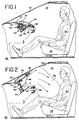
- FIGS. 1-2 a motor vehicle 20 having a passenger compartment 22 for accommodating a person 24 in seated position on a vehicle seat 26.
- the vehicle 20 forward of the occupant 24, the vehicle 20 includes a dashboard 28 and a panel 30 having an enlarged opening 32 spaced directly above an airbag and inflator assembly generally indicated by the reference numeral 34.
- the airbag and inflator assembly 34 includes a housing or canister 36 fixedly mounted in place beneath the panel 30 and the opening 32.
- An airbag 38 in deflated condition is stored and contained within the housing 36 until deployed as illustrated in FIG. 2 to protect the vehicle occupant 24 from injury in an accident.
- the panel opening 32 is normally closed by a movable cover 40, which as shown in FIGS. 1 and 4 forms part of the upper surface of the panel 30 above the opening 32.
- a movable cover 40 which as shown in FIGS. 1 and 4 forms part of the upper surface of the panel 30 above the opening 32.
- the cover 40 includes an outer skin 44 and an inner skin 46 integrally formed in a single piece and thereafter folded over along a forward edge 47 (FIG. 6).
- the integral skins 44 and 46 are constructed of molded resinous plastic material such as polypropylene to provide strength and integrity for the cover 40 as a whole so that break up or fracture of the cover into several pieces does not occur upon airbag deployment.
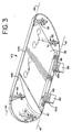
- the cover 40 Normally the cover 40 is retained in a closed position (FIG. 1) directly above and over the panel opening 32 by a plurality of break-away fasteners 52 provided at opposite end portions of the cover (FIG. 3). Inner ends 52b of the fasteners 52 are inserted in and snap locked into apertures 54 (FIGS. 4 and 4A) provided in a lower flange 30a of the panel 30, at the opposite ends of the opening 32. Until the airbag 38 is deployed, the cover 40 acts as an integrated part of the panel 30 and at the same time protects the airbag assembly 34 from damage by limiting external access thereto.
- each leg 52a of a fastener 52 is notched as at 52c to provide a fracture line of reduced cross-section.
- the legs 52a of each latch element are readily fractured or broken at the notches 52c to release the cover 40 to move bodily away from the panel opening 32 from the closed position of FIG. 1 to the open position of FIG. 2.
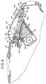
- one or more tethers 60 of strong, flexible material such as "Nylon” webbing, scrim material, web belting, or the like is interconnected between the underside of the cover 40 and the housing or canister 36 of the airbag inflator assembly 34. Inner ends of the flexible tethers 60 are interconnected to the upper sidewall of the canister 36 by means of metal or plastic clips 62 (FIG. 4).
- the cover 40 including the integral inner and outer skins 46 and 44 is formed in a single mold 80 as shown in FIG. 5.
- the molded resinous plastic piece is removed from the cavity of the mold 80 as a single piece or unitary member comprising both of the integrally molded skins 44 and 46.
- the respective inner and outer skins 46 and 44 are folded over on one another into an overlying relation as shown in FIG. 6 about a fold line 47 extending along and forming a forward edge of the cover 40.
- an inside face 44a of the outer skin 44 is molded to include one or more pairs of spaced apart positioning ribs 64 which are normal to the inside face and which extend toward a facing portion of an inside face 46a of the folded over inner skin 46.
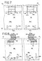
- Each pair of positioning ribs 64 is spaced apart by a distance "d" (FIG. 7) slightly greater than the width "w” (FIG. 6) of the tethers 60.
- Parallel facing surfaces of each pair of ribs 64 form guide surfaces 64a for facilitating the passage of looped, outer end portions 60a of the tethers 60 (FIG.
- an elongated anchor bar 70 formed of a metal strip or strip of stiff, strong plastic material for spreading loads exerted by the tethers 60 over a wide area extending generally parallel of the fold line 47 for a substantial portion of the length of the cover 40.
- Outer edges of the ribs 64 are formed with recess 64b of trapezoidal shape (FIGS. 5 and 6) for positioning the anchor bar 70 parallel relative to the fold line 47 and substantially close to or flush with the adjacent inside surface 46a of the folded over inner skin 46.
- the inner skin 46 is formed with slots 73 (FIGS. 6 and 8) aligned with the center line of anchor bar 70 in order to permit the looped outer end portions 60a of the tethers 60 to pass out through the inner skin 46 and extend toward the airbag housing 36.
- a bitter end of each tether 60 is stitched as at 65 or otherwise permanently fastened to the body of the tether.
- the outer skin 44 is formed with a downturned edge flange 44b against which an edge 46b of the inner skin 46 abuts when the inner and outer skins are folded over ready for joining together along a rearward edge portion of the cover 40.
- Heat stakes 44c are integrally molded on the inside surface 44a of the outer skin 44 and are positioned at spaced apart intervals in a row adjacent and inwardly of the edge 46b.
- the inner skin 46 is formed with appropriately positioned slots 46c to receive the heat stakes 44c and outer ends of the heat stakes are spread and deformed as caps 51 in a heat staking operation to secure the inner and outer skins 46 and 44 together along a rearward edge portion of the cover 40.
- the cover tether combination of the present invention provides for spreading the restraining load exerted by the tethers 60 on the cover 40 over a substantially large area thereon by means of the internal anchor bar 70 placed between the inner and outer skins 46 and 44.
- the one piece, integrally formed folded over resinous plastic inner and outer skins 46 and 44 provide an exceedingly strong cover structure and the anchor bar 70 serves as further internal reinforcement which reduces stress and minimizes the chances of severance of the cover 40 from the tethers 60 or break up or fracture of the cover into pieces.
Landscapes
- Engineering & Computer Science (AREA)
- Mechanical Engineering (AREA)
- Air Bags (AREA)
Claims (12)
- Airbagsystem für Kraftfahrzeuge (20) und dergleichen, mit einem aufblasbaren Airbag (38), der in einem nicht aufgeblasenen Zustand in einem Gehäuse (36) angeordnet ist, wobei das Gehäuse ein offenes Ende besitzt, um den Airbag hinauszulassen, wenn er aufgeblasen ausgebreitet ist, um dämpfenden Schutz für eine auf einem Fahrzeugsitz (26) sitzende Person zu bieten, bestehend aus:Abdeckmitteln (40), die an dem offenen Ende des Gehäuses normalerweise eine Öffnung (42) in der Verkleidung abdecken, um den Airbag zu schützen, wobei die Abdeckmittel beweglich sind, um die Öffnung während des Entfaltens des Airbags aufzudecken;flexiblen Anbindungsmitteln (60) zwischen den Abdeckmitteln und wenigstens einem der Verkleidungs- und Gehäusemittel (36), um die Bewegung der Abdeckmittel weg von den Verkleidungsmitteln zu begrenzen, wenn der Airbag sich aufgeblasen entfaltet;wobei die Abdeckmittel integriert eine äußere (44) und eine innere (46) Wand aufweisen, die an einem Endbereich (47) umgefaltet ist, wobei die innere Wand einen Schlitz (73) aufweist, um einen Durchgang für die Verbindungsmittel in den Raum zwischen den Wänden zu bieten; undVerankerungsmitteln in dem Raum, die aus einem länglichen Riegel (70) aus einem steifen Material bestehen und mit den Verbindungsmitteln in Eingriff stehen, um diese an den Abdeckmitteln zu sichern;
dadurch gekennzeichnet, daß die äußere Wand (44) der Abdeckmittel mit einem oder mehreren Haltemitteln (64) ausgebildet ist, die sich in Richtung auf die innere Wand (46) in dem Raum erstrecken, um mit den Verankerungsmitteln (70) in Eingriff zu stehen um diese in Position zu halten. - Airbagsystem nach Anspruch 1, dadurch gekennzeichnet,daß die Verankerungsmittel (70) sich über den Schlitz hinweg erstrecken, um die Kraft, die durch die Verbindungsmittel ausgeübt wird über einen großen Bereich der inneren Wand zu verteilen, wenn sich der Airbag entfaltet.
- Airbagsystem nach Anspruch 2, dadurch gekennzeichnet,daß die Verbindungsmittel einen ersten Teil (60a) aufweisen, der um die Verankerungsmittel (70) geschlungen ist.
- Airbagsystem nach Anspruch 1, dadurch gekennzeichnet,daß die innere (46) und die äußere (44) Wand zusammen als einstückiges Teil gespritzt sind und danach entlang einer Linie (47) gefaltet sind, die sich über das eine Ende der Abdeckmittel erstreckt.
- Airbagsystem nach Anspruch 4, dadurch gekennzeichnet,daß die innere und die äußere Wand auch an dem gegenüberliegenden Ende (46b) der Abdeckmittel in einem Abstand zu der Faltlinie miteinander verbunden sind.
- Airbagsystem nach Anspruch 5, dadurch gekennzeichnet,daß die innere und die äußere Wand an dem entgegengesetzten Ende der Abdeckmittel durch Heißfügestege miteinander verbunden sind.
- Airbagsystem nach Anspruch 6, dadurch gekennzeichnet,
daß:die äußere Wand mit wenigstens einem Heißfügesteg (44c) ausgebildet ist, der sich zu der inneren Wand hin erstreckt und daß die innere Wand eine Öffnung (46c) aufweist, um den Heißfügesteg aufzunehmen. - Airbagsystem nach Anspruch 7, dadurch gekennzeichnet,
daß:die äußere Wand eine Mehrzahl von Heißfügestegen (44c) aufweist, die in Abstaänden zueinander an dem entgegengestzten Ende der Abdeckmittel angeordnet sind und daß die innere Wand eine Mehrzahl passender Öffnungen (46c) aufweist, die jeweils einen Heißfügesteg aufnehmen. - Airbagsystem nach Anspruch 7, dadurch gekennzeichnet,
daß:der Heißfügesteg durch Hitze, Ultraschall oder andere Mittel an seinem äußeren Ende verformt ist, um an einer Außenseite der inneren Wand anzuliegen, um die innere und die äußere Wand entlang des entgegengestzten Endes der Abdeckmittel fest miteinander zu verbinden. - Airbagsystem nach Anspruch einem der Ansprüche 1 bis 9, dadurch gekennzeichnet, daß:die Haltemittel (64)Oberflächen (64a) aufweisen, die die Verbindungsmittel so zu führen, daß das äußere Endteil (60a) mit die Verankerungsmittel geschlungen ist..
- Airbagsystem nach Anspruch 10, dadurch gekennzeichnet, daß:die Haltemittel wenigstens ein Paar Rippen (64) aufweisen, die integriert an einer (44) der Wände geformt sind, um sich auf die gegenüberliegende Oberfläche der anderen (46) hin zu erstrecken und die die entgegengesetzten Seiten des äußeren Endbereichs der Verbindungsmittel, die um die Verankerungsmittel geschlungen sind, einschließen.
- Airbagsystem nach Anspruch 11, dadurch gekennzeichnet, daß:die Rippen (64) an den Enden des Schlitzes (73) der inneren Wand angeordnet sind.
Applications Claiming Priority (2)
| Application Number | Priority Date | Filing Date | Title |
|---|---|---|---|
| US311220 | 1981-10-14 | ||
| US08/311,220 US5474324A (en) | 1994-11-07 | 1994-11-07 | Tethered cover airbag system |
Publications (2)
| Publication Number | Publication Date |
|---|---|
| EP0710592A1 EP0710592A1 (de) | 1996-05-08 |
| EP0710592B1 true EP0710592B1 (de) | 1999-10-13 |
Family
ID=23205941
Family Applications (1)
| Application Number | Title | Priority Date | Filing Date |
|---|---|---|---|
| EP95402439A Expired - Lifetime EP0710592B1 (de) | 1994-11-07 | 1995-11-02 | Airbagvorrichtungsabdeckung mit Verbindungsband |
Country Status (4)
| Country | Link |
|---|---|
| US (1) | US5474324A (de) |
| EP (1) | EP0710592B1 (de) |
| JP (1) | JP3024388U (de) |
| DE (1) | DE69512738T2 (de) |
Families Citing this family (19)
| Publication number | Priority date | Publication date | Assignee | Title |
|---|---|---|---|---|
| US5553887A (en) * | 1995-09-29 | 1996-09-10 | Takata Inc. | Inflatable restraint modular housing with deployment directing feature |
| GB9625395D0 (en) * | 1996-12-06 | 1997-01-22 | Ford Motor Co | Improvements relating to airbag door tethering devices |
| DE19653174A1 (de) * | 1996-12-19 | 1998-06-25 | Bayerische Motoren Werke Ag | Abdeckung für eine Gassackrückhalteeinrichtung |
| GB2367535B (en) * | 2000-10-03 | 2003-11-12 | Autoliv Dev | Improvements in or relating to a strap connection |
| US6431585B1 (en) * | 2000-10-05 | 2002-08-13 | Lear Corporation | Dual stage fastener |
| US6851710B2 (en) | 2001-03-06 | 2005-02-08 | Autoliv Asp, Inc. | Apparatus and method for rapid airbag component installation |
| US6889999B2 (en) | 2002-03-20 | 2005-05-10 | Autoliv Asp, Inc. | Airbag tether retainer |
| US7125037B2 (en) * | 2003-10-21 | 2006-10-24 | Autoliv Asp, Inc. | Inflatable cushion retention system |
| US20050104338A1 (en) * | 2003-11-19 | 2005-05-19 | Quin Soderquist | Applique film airbag cover |
| US7278654B2 (en) * | 2004-01-30 | 2007-10-09 | Collins & Aikman Products Co. | Stiffening frame for an integral tether and tearstop in an air bag door |
| US7156415B2 (en) * | 2004-01-30 | 2007-01-02 | Collins & Aikman Products Co. | Stiffening frame for an integral tether and tearstop in an air bag door |
| JP4797584B2 (ja) * | 2005-03-16 | 2011-10-19 | タカタ株式会社 | エアバッグ装置付きステアリングホイール |
| US7793972B2 (en) * | 2007-03-14 | 2010-09-14 | Nissan Technical Center North America, Inc. | Front pillar trim panel with tether |
| JP2011000962A (ja) * | 2009-06-18 | 2011-01-06 | Honda Motor Co Ltd | 鞍乗型車両のエアバッグ装置 |
| FR2957871B1 (fr) * | 2010-03-24 | 2012-04-20 | Faurecia Interieur Ind | Volet de coussin de securite gonflable articule sur une planche de bord par un lien agence pour liberer une longueur supplementaire de lien sur ouverture de ce volet |
| JP5120436B2 (ja) * | 2010-10-05 | 2013-01-16 | トヨタ自動車株式会社 | 助手席用エアバッグ装置 |
| DE102010051421A1 (de) * | 2010-11-17 | 2012-05-24 | Trw Automotive Gmbh | Fahrzeuginsassen-Rückhaltesystem und Verfahren zum Rückhalten eines Fahrzeuginsassen |
| JP6689894B2 (ja) * | 2018-01-15 | 2020-04-28 | 本田技研工業株式会社 | 車両のエアバッグ装置 |
| GB2603180B (en) * | 2021-01-29 | 2025-02-12 | Jaguar Land Rover Ltd | A vehicle trim assembly |
Citations (1)
| Publication number | Priority date | Publication date | Assignee | Title |
|---|---|---|---|---|
| EP0695670A1 (de) * | 1994-08-05 | 1996-02-07 | Morton International, Inc. | Abbrechbares Befestigungssystem für Luftsack-Entfaltungsdeckel |
Family Cites Families (18)
| Publication number | Priority date | Publication date | Assignee | Title |
|---|---|---|---|---|
| DE2052357A1 (de) | 1970-10-24 | 1972-04-27 | Lenkradwerk Gustav Petri Ag, 8750 Aschaffenburg | Lenkrad mit eingebautem Luftkissen |
| GB1358364A (en) | 1971-12-03 | 1974-07-03 | Daimler Benz Ag | Vehicle with automatically inflatable protective gas cushion |
| JP2509277B2 (ja) * | 1988-02-09 | 1996-06-19 | 日産自動車株式会社 | 自動車のエアバッグ装置 |
| US4893833A (en) | 1988-09-08 | 1990-01-16 | Tip Engineering Group, Inc. | Closure for an air bag deployment opening |
| DE3843686A1 (de) | 1988-12-23 | 1990-06-28 | Bayerische Motoren Werke Ag | Abdeckung fuer airbaganordnung in einem kraftfahrzeug |
| JPH0626457Y2 (ja) | 1989-08-08 | 1994-07-20 | 豊田合成株式会社 | エアバツグ装置のパツド |
| US4964653A (en) | 1989-08-24 | 1990-10-23 | Davidson Textron Inc. | Self-skinned foam component for an inflatable restraint door assembly |
| EP0415362B1 (de) | 1989-08-30 | 1995-06-14 | Mazda Motor Corporation | Gassack-Vorrichtung für ein Kraftfahrzeug |
| US5195776A (en) * | 1990-03-27 | 1993-03-23 | Mazda Motor Corporation | Air bag installation |
| US5072967A (en) | 1990-07-12 | 1991-12-17 | Davidson Textron Inc. | Instrument panel with invisible airbag deployment door |
| JP2890757B2 (ja) | 1990-09-05 | 1999-05-17 | トヨタ自動車株式会社 | エアバッグドア開放機構 |
| US5242191A (en) | 1991-01-18 | 1993-09-07 | Trw Vehicle Safety Systems Inc. | Tethered air bag cover |
| US5096221A (en) | 1991-02-21 | 1992-03-17 | Davidson Textron Inc. | Air bag door with plural substrates |
| US5211421A (en) | 1992-02-24 | 1993-05-18 | General Motors Corporation | Air bag cover door retainer |
| JPH05338513A (ja) * | 1992-06-09 | 1993-12-21 | Toyota Motor Corp | サイドエアバッグ装置のカバー取付構造 |
| US5219177A (en) | 1992-06-19 | 1993-06-15 | General Motors Corporation | Releasable latch for air bag deployment door |
| JP3203813B2 (ja) * | 1992-10-16 | 2001-08-27 | タカタ株式会社 | 助手席用エアバッグ装置 |
| US5385366A (en) * | 1993-09-07 | 1995-01-31 | General Motors Corporation | Air bag deflection shield |
-
1994
- 1994-11-07 US US08/311,220 patent/US5474324A/en not_active Expired - Fee Related
-
1995
- 1995-11-02 EP EP95402439A patent/EP0710592B1/de not_active Expired - Lifetime
- 1995-11-02 DE DE69512738T patent/DE69512738T2/de not_active Expired - Fee Related
- 1995-11-07 JP JP1995011753U patent/JP3024388U/ja not_active Expired - Lifetime
Patent Citations (1)
| Publication number | Priority date | Publication date | Assignee | Title |
|---|---|---|---|---|
| EP0695670A1 (de) * | 1994-08-05 | 1996-02-07 | Morton International, Inc. | Abbrechbares Befestigungssystem für Luftsack-Entfaltungsdeckel |
Also Published As
| Publication number | Publication date |
|---|---|
| DE69512738D1 (de) | 1999-11-18 |
| JP3024388U (ja) | 1996-05-21 |
| EP0710592A1 (de) | 1996-05-08 |
| US5474324A (en) | 1995-12-12 |
| DE69512738T2 (de) | 2000-06-08 |
Similar Documents
| Publication | Publication Date | Title |
|---|---|---|
| US5460401A (en) | Airbag system with tethered cover | |
| US5472228A (en) | Break-away fastening system for air bag deployment doors | |
| EP0710592B1 (de) | Airbagvorrichtungsabdeckung mit Verbindungsband | |
| EP0695671B1 (de) | Airbag-System mit Rückhalteband für Deckel | |
| EP0722862B1 (de) | Deckel für eine Wandöffnung in einem Luftsack-Aufprallschutz-System | |
| US6719320B2 (en) | Controlled tether arrangement for an airbag | |
| KR100282950B1 (ko) | 자동차용 승객 보호 장치의 배치 구조 | |
| JP3042494U (ja) | エアバッグモデュールドア | |
| US5613701A (en) | Break-away fastening system for air bag deployment doors | |
| US5647607A (en) | Tether attachment apparatus for air bag cover | |
| US7249782B2 (en) | Dynamic/controlled tether arrangement for an airbag door | |
| JP3321978B2 (ja) | エアバッグ装置 | |
| US5498027A (en) | Seamless door for air bag module | |
| JP3195306B2 (ja) | 自動車のエアバッグ拘束装置のカバー | |
| US5971427A (en) | Side impact air bag clamshell-wrap around strap closure | |
| US20020125693A1 (en) | Hinging reinforced trim piece | |
| JP3051225U (ja) | カバー及びハウジングの組立体 | |
| US6290252B1 (en) | Air bag module | |
| KR200144273Y1 (ko) | 조수석 에어백장치의 커버 | |
| KR20060130290A (ko) | 조수석 에어백 모듈의 도어 조립 구조 |
Legal Events
| Date | Code | Title | Description |
|---|---|---|---|
| PUAI | Public reference made under article 153(3) epc to a published international application that has entered the european phase |
Free format text: ORIGINAL CODE: 0009012 |
|
| AK | Designated contracting states |
Kind code of ref document: A1 Designated state(s): DE FR GB IT |
|
| 17P | Request for examination filed |
Effective date: 19960723 |
|
| 17Q | First examination report despatched |
Effective date: 19970702 |
|
| GRAG | Despatch of communication of intention to grant |
Free format text: ORIGINAL CODE: EPIDOS AGRA |
|
| GRAG | Despatch of communication of intention to grant |
Free format text: ORIGINAL CODE: EPIDOS AGRA |
|
| GRAH | Despatch of communication of intention to grant a patent |
Free format text: ORIGINAL CODE: EPIDOS IGRA |
|
| GRAH | Despatch of communication of intention to grant a patent |
Free format text: ORIGINAL CODE: EPIDOS IGRA |
|
| GRAA | (expected) grant |
Free format text: ORIGINAL CODE: 0009210 |
|
| AK | Designated contracting states |
Kind code of ref document: B1 Designated state(s): DE FR GB IT |
|
| PG25 | Lapsed in a contracting state [announced via postgrant information from national office to epo] |
Ref country code: IT Free format text: LAPSE BECAUSE OF FAILURE TO SUBMIT A TRANSLATION OF THE DESCRIPTION OR TO PAY THE FEE WITHIN THE PRE;WARNING: LAPSES OF ITALIAN PATENTS WITH EFFECTIVE DATE BEFORE 2007 MAY HAVE OCCURRED AT ANY TIME BEFORE 2007. THE CORRECT EFFECTIVE DATE MAY BE DIFFERENT FROM THE ONE RECORDED.SCRIBED TIME-LIMIT Effective date: 19991013 |
|
| REF | Corresponds to: |
Ref document number: 69512738 Country of ref document: DE Date of ref document: 19991118 |
|
| ET | Fr: translation filed | ||
| PLBE | No opposition filed within time limit |
Free format text: ORIGINAL CODE: 0009261 |
|
| STAA | Information on the status of an ep patent application or granted ep patent |
Free format text: STATUS: NO OPPOSITION FILED WITHIN TIME LIMIT |
|
| 26N | No opposition filed | ||
| REG | Reference to a national code |
Ref country code: FR Ref legal event code: TP Ref country code: FR Ref legal event code: CD |
|
| REG | Reference to a national code |
Ref country code: GB Ref legal event code: 732E |
|
| REG | Reference to a national code |
Ref country code: GB Ref legal event code: IF02 |
|
| PGFP | Annual fee paid to national office [announced via postgrant information from national office to epo] |
Ref country code: GB Payment date: 20031029 Year of fee payment: 9 |
|
| PGFP | Annual fee paid to national office [announced via postgrant information from national office to epo] |
Ref country code: FR Payment date: 20031119 Year of fee payment: 9 |
|
| PG25 | Lapsed in a contracting state [announced via postgrant information from national office to epo] |
Ref country code: GB Free format text: LAPSE BECAUSE OF NON-PAYMENT OF DUE FEES Effective date: 20041102 |
|
| GBPC | Gb: european patent ceased through non-payment of renewal fee |
Effective date: 20041102 |
|
| PG25 | Lapsed in a contracting state [announced via postgrant information from national office to epo] |
Ref country code: FR Free format text: LAPSE BECAUSE OF NON-PAYMENT OF DUE FEES Effective date: 20050729 |
|
| REG | Reference to a national code |
Ref country code: FR Ref legal event code: ST |
|
| PGFP | Annual fee paid to national office [announced via postgrant information from national office to epo] |
Ref country code: DE Payment date: 20070102 Year of fee payment: 12 |
|
| PG25 | Lapsed in a contracting state [announced via postgrant information from national office to epo] |
Ref country code: DE Free format text: LAPSE BECAUSE OF NON-PAYMENT OF DUE FEES Effective date: 20080603 |