EP0710792B1 - Vorrichtung für die Vorverformung eines Rohres aus Kunststoff oder elastisch verformbarem Material - Google Patents
Vorrichtung für die Vorverformung eines Rohres aus Kunststoff oder elastisch verformbarem Material Download PDFInfo
- Publication number
- EP0710792B1 EP0710792B1 EP95402382A EP95402382A EP0710792B1 EP 0710792 B1 EP0710792 B1 EP 0710792B1 EP 95402382 A EP95402382 A EP 95402382A EP 95402382 A EP95402382 A EP 95402382A EP 0710792 B1 EP0710792 B1 EP 0710792B1
- Authority
- EP
- European Patent Office
- Prior art keywords
- conduit
- pieces
- cages
- bars
- cage
- Prior art date
- Legal status (The legal status is an assumption and is not a legal conclusion. Google has not performed a legal analysis and makes no representation as to the accuracy of the status listed.)
- Expired - Lifetime
Links
Images
Classifications
-
- F—MECHANICAL ENGINEERING; LIGHTING; HEATING; WEAPONS; BLASTING
- F16—ENGINEERING ELEMENTS AND UNITS; GENERAL MEASURES FOR PRODUCING AND MAINTAINING EFFECTIVE FUNCTIONING OF MACHINES OR INSTALLATIONS; THERMAL INSULATION IN GENERAL
- F16L—PIPES; JOINTS OR FITTINGS FOR PIPES; SUPPORTS FOR PIPES, CABLES OR PROTECTIVE TUBING; MEANS FOR THERMAL INSULATION IN GENERAL
- F16L47/00—Connecting arrangements or other fittings specially adapted to be made of plastics or to be used with pipes made of plastics
-
- F—MECHANICAL ENGINEERING; LIGHTING; HEATING; WEAPONS; BLASTING
- F16—ENGINEERING ELEMENTS AND UNITS; GENERAL MEASURES FOR PRODUCING AND MAINTAINING EFFECTIVE FUNCTIONING OF MACHINES OR INSTALLATIONS; THERMAL INSULATION IN GENERAL
- F16L—PIPES; JOINTS OR FITTINGS FOR PIPES; SUPPORTS FOR PIPES, CABLES OR PROTECTIVE TUBING; MEANS FOR THERMAL INSULATION IN GENERAL
- F16L3/00—Supports for pipes, cables or protective tubing, e.g. hangers, holders, clamps, cleats, clips, brackets
- F16L3/08—Supports for pipes, cables or protective tubing, e.g. hangers, holders, clamps, cleats, clips, brackets substantially surrounding the pipe, cable or protective tubing
- F16L3/10—Supports for pipes, cables or protective tubing, e.g. hangers, holders, clamps, cleats, clips, brackets substantially surrounding the pipe, cable or protective tubing divided, i.e. with two members engaging the pipe, cable or protective tubing
-
- Y—GENERAL TAGGING OF NEW TECHNOLOGICAL DEVELOPMENTS; GENERAL TAGGING OF CROSS-SECTIONAL TECHNOLOGIES SPANNING OVER SEVERAL SECTIONS OF THE IPC; TECHNICAL SUBJECTS COVERED BY FORMER USPC CROSS-REFERENCE ART COLLECTIONS [XRACs] AND DIGESTS
- Y10—TECHNICAL SUBJECTS COVERED BY FORMER USPC
- Y10S—TECHNICAL SUBJECTS COVERED BY FORMER USPC CROSS-REFERENCE ART COLLECTIONS [XRACs] AND DIGESTS
- Y10S138/00—Pipes and tubular conduits
- Y10S138/08—Bent shaped retained
Definitions
- the invention relates to a conduit or pipe made of plastic or elastically deformable material such as an elastomer or a rubber, of the type usable in particular in the automotive industry, associated with a shaping device.
- Ducts or pipes of relatively diameter important which are mounted in the engine compartments motor vehicles often require formatting devices to modify their shape in section, in particular in the sense of the flattening, and / or their direction, for example for work around an obstacle, the need for these devices being mainly due to the lack of available space in an engine compartment, which requires bending and flatten certain parts of the conduits or pipes to manage to house them in the desired places.
- the invention aims to provide a solution simple, effective and inexpensive to these problems.
- Its purpose is a device for form of a conduit or pipe, which can be mounted at any time on any part of the conduit or pipe to change its shape in section transverse and possibly its direction, which is also removable and which does not require the use of special tools for its assembly or disassembly.
- this duct having a certain cross-section initial and being associated with a setting device form comprising at least two rigid parts provided with fastening means one on the other and intended to be assembled around the duct by defining between them a housing for receiving this conduit, this housing having a shape in cross section different from the shape initial cross section of the duct and corresponding to a desired shape of the part cross section of the duct, so that when the pieces are fixed to each other around the duct, they deform and give it in cross section the shape desired above.
- the means for fixing the pieces one on top of the other are hooking means or elastic snap.
- the aforementioned parts are half-cages formed bars rigidly connected together.
- Each piece or half-cage is preferably molded in one piece from relatively soft plastic rigid, for example of polyamide filled with fibers of glass.
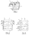
- Figures 1 to 5 represent schematically a first embodiment of the invention, in which a setting device form of a plastic conduit or pipe, in elastomer or rubber, consists of two half-cages identical 10 which can be assembled one to the other by snap or elastic snap and which, when they are placed around a duct, give the latter an elliptical shape in section transverse.
- Each half-cage 10 is molded of material rigid plastic, such as a fiber-filled polyamide glass, and includes three longitudinal bars 12 parallel and rectilinear interconnected by three bars parallel transverse 14 having the shape of a half ellipse.
- the transverse bars 14 are respectively at the ends and in the middle of the half-cage 10, and the longitudinal bars 12 connect the ends together transverse bars 14 and the middle parts of these bars, respectively.
- One of the longitudinal bars 12 connecting the ends of the transverse bars 14, comprises two hook tabs 16 which each extend between two transverse bars 14 and opposite the latter, tangentially to the half-ellipse defined by the half-cage 10 as can be seen in FIG. 4.
- Each tab 16 comprises a protruding beak 18 on its outer face, this spout 18 having a shape of arrowhead.
- the other longitudinal bar 12 connecting the ends of the transverse bars 14 of the half-cage 10 includes notches 20 on its inner face, these notches being intended to allow the passage of legs 16 and beaks 18 of another identical half-cage when assembling the device.
- the transverse bars 14 at the end of the cage 10 are formed with a projection 22 to oblique ramp at one end and with a notch 24 correspondingly shaped at their other end (figure 5).
- positioning pins 26 can be formed at the ends of one of the longitudinal bars 12 end ( Figure 3) to extend into the same direction as legs 16 while the other bar longitudinal end 12 includes orifices intended to receive the positioning pins 26 from another identical half-cage.
- the assembly of the device for implementing the invention is very simple: it suffices to have two identical half-cages 10 face to face as shown in FIG. 4, the legs 16 of a half-cage being aligned with the notches 20 of the other half-cage and vice versa, and to push the half -cages towards each other to automatically fix the half-cages to each other by hooking and elastic snap-fastening, the spouts 18 of the tabs 16 sliding on the edges of the notches 20 until snap-fastening elastic on the bars 12.
- the half-cages are made of a material sufficiently rigid and mechanically resistant to keep their shape in case the pressure at the inside of the duct becomes significantly higher than the ambient pressure.
- the device is removable without difficulty: just push the legs 16 inward and pull the half cages 10 for separate them from each other.
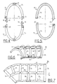
- Figures 6 and 7 differs from the one that has just been described in that it allows, not only to change the cross-sectional shape of the duct on which it is mounted, but also to modify the direction of this conduit, for example by bending it at 45 °.
- This device therefore includes, like the previous one, two identical or substantially identical half-cages 30, made of molded plastic and made of parallel longitudinal bars 32 connected between them by transverse bars 34 of semi-elliptical shape, the longitudinal bars 32 being rectilinear over part of their length and curved in an arc of circle in the vicinity of one of their ends, of such that a cross bar 34 located at one end of the half-cage is inclined by 45 °, for example, relative to the transverse bar 34 located at the other end of the half-cage.
- the longitudinal bars 32 are parallel to the longitudinal axis of symmetry a of the device, while the transverse bars 34 extend in planes perpendicular to this axis.
- a half-bar transverse 36 in quarter ellipse is provided between the two transverse bars 34 which connect the curved parts of the longitudinal bars 32, this half-bar transverse 36 extending between the longitudinal bar 32 located radially outermost by relative to the center of curvature of the curved ends bars 32, and the longitudinal bar 32 connecting the middle of cross bars 34.
- Figures 6 and 7 still differs from that of FIGS. 1 to 5 in that it comprises a half-cage of the male type comprising means elastic attachment or latching such as legs 16 of the previous embodiment, the other half-cage being of the female type and comprising the notches which will receive these means of hooking or snap-fastening elastic, the half-cage 30 shown in Figures 6 and 7 being of the female type.
- this half-cage 30 includes pins 38 protruding from one of the longitudinal bars 32, to receive for example a rubber pad which will serve as a support stop on a support.
- the faces of the bars 12, 14, 32, 34 which face the inside of the half-cages are substantially flat or slightly curved and tangential to the elliptical cross-sectional area defined by the half cages.
- the invention allows a setting simple, fast and reliable form of a conduit or pipe plastic or elastically deformable material, by means of a device which is mountable and dismountable without special tools.
- the half cages that come to be described can be replaced by half shells with solid walls or more or less openwork.
- the device according to the invention can be constituted by assembling and fixing more than two pieces, and it can be designed to change multiple times the form and eventually The direction of a conduit, for example for give an S or U shape to a part of the duct, if need is.
Landscapes
- Engineering & Computer Science (AREA)
- General Engineering & Computer Science (AREA)
- Mechanical Engineering (AREA)
- Supports For Pipes And Cables (AREA)
- Rigid Pipes And Flexible Pipes (AREA)
- Mutual Connection Of Rods And Tubes (AREA)
- Cooling, Air Intake And Gas Exhaust, And Fuel Tank Arrangements In Propulsion Units (AREA)
- Duct Arrangements (AREA)
Claims (9)
- Rohr aus Kunststoff oder elastisch verformbaren Material, wobei dieses Rohr im Querschnitt eine gewisse anfängliche Form hat und mit einer Vorrichtung zum Formen verbunden wird, die wenigstens zwei starre Teile (10, 30) umfaßt, welche mit Mitteln (16, 18, 20) zur Befestigung des einen auf dem anderen versehen und dazu bestimmt sind, um die Leitung zusammengebaut zu werden, indem sie zwischen sich eine Unterbringung für die Aufnahme dieses Rohrs abgrenzen, wobei diese Unterbringung eine Querschnittsform hat, die unterschiedlich von der anfänglichen Querschnittsform des Rohrs ist und einer gewünschten Form des Querteils des Rohrs entspricht, derart, daß, wenn die Teile (10, 30) eins mit dem anderen um das Rohr befestigt werden, sie dasselbe verformen und ihm im Querschnitt die gewünschte vorgenannte Form geben.
- Rohr gemäß Anspruch 1, dadurch gekennzeichnet, daß die Mittel für die Befestigung der Teile (10, 30) Mittel (16, 18, 20) des Verhakens oder der elastischen Verklinkung sind.
- Rohr gemäß Anspruch 1 oder 2, dadurch gekennzeichnet, daß die vorgenannten Teile Halbkäfige (10, 30) sind, die von Stäben (12, 14, 32, 34) gebildet sind, welche starr miteinander verbunden sind.
- Rohr gemäß einem der vorhergehenden Ansprüche, dadurch gekennzeichnet, daß jedes Teil oder jeder vorerwähnte Halbkäfig aus einem einzigen Stück aus starrem Kunststoff geformt ist.
- Rohr gemäß Anspruch 4, dadurch gekennzeichnet, daß der genannte Kunststoff ein Polyamid ist, das von Glasfasern durchsetzt bzw. mit Glasfasern beladen ist.
- Rohr gemäß einem der vorhergehenden Ansprüche, dadurch gekennzeichnet, daß die vorerwähnten Teile oder Halbkäfige (10, 30) Mittel (38) für die Befestigung oder die Aufnahme von Zubehör, wie Anschläge bzw. Widerlager für die Abstützung bzw. Auflage auf einem Träger oder Organe für die Befestigung auf einem Träger umfassen.
- Rohr gemäß einem der vorhergehenden Ansprüche, dadurch gekennzeichnet, daß die Vorrichtung zum Formen von elliptischem Querschnitt ist.
- Rohr gemäß einem der vorhergehenden Ansprüche, dadurch gekennzeichnet, daß die Vorrichtung zum Formen eine generell gekrümmte Form hat, die wenigstens einer Richtungsänderung des Rohrs entspricht.
- Rohr gemäß einem der vorhergehenden Ansprüche, dadurch gekennzeichnet, daß die vorgenannten Teile oder Halbkäfige (10, 30) von Längsstäben (12), die parallel zur Längsachse der Vorrichtung sind, und gekrümmten Querstäben (14, 34), die im wesentlichen senkrecht zu dieser Achse sind, gebildet sind.
Applications Claiming Priority (2)
| Application Number | Priority Date | Filing Date | Title |
|---|---|---|---|
| FR9413190A FR2726625B1 (fr) | 1994-11-04 | 1994-11-04 | Dispositif de mise en forme d'un conduit en matiere plastique ou en matiere elastiquement deformable |
| FR9413190 | 1994-11-04 |
Publications (2)
| Publication Number | Publication Date |
|---|---|
| EP0710792A1 EP0710792A1 (de) | 1996-05-08 |
| EP0710792B1 true EP0710792B1 (de) | 1999-03-31 |
Family
ID=9468499
Family Applications (1)
| Application Number | Title | Priority Date | Filing Date |
|---|---|---|---|
| EP95402382A Expired - Lifetime EP0710792B1 (de) | 1994-11-04 | 1995-10-25 | Vorrichtung für die Vorverformung eines Rohres aus Kunststoff oder elastisch verformbarem Material |
Country Status (5)
| Country | Link |
|---|---|
| US (1) | US5989006A (de) |
| EP (1) | EP0710792B1 (de) |
| DE (1) | DE69508701T2 (de) |
| ES (1) | ES2132564T3 (de) |
| FR (1) | FR2726625B1 (de) |
Families Citing this family (13)
| Publication number | Priority date | Publication date | Assignee | Title |
|---|---|---|---|---|
| US6354937B1 (en) | 2000-02-05 | 2002-03-12 | Dale J. Crook | Flexible duct sleeve |
| DE202006008578U1 (de) * | 2006-05-30 | 2007-10-11 | Veritas Ag | Stabilisierungselement für einen Wellschlauch |
| US7914047B2 (en) * | 2007-09-20 | 2011-03-29 | Crook Dale J | Support for flexible duct bend |
| US8038175B2 (en) * | 2007-09-20 | 2011-10-18 | Crook Dale J | HVAC duct assembly and support |
| USD580543S1 (en) | 2007-09-20 | 2008-11-11 | Crook Dale J | Elbow for flexible duct |
| DE102009005643B4 (de) * | 2009-01-22 | 2017-03-30 | Siemens Healthcare Gmbh | Vorrichtung zur Erhöhung der Biegesteifigkeit von Schläuchen |
| US8844578B2 (en) * | 2010-11-19 | 2014-09-30 | Rite-Hite Holding Corporation | Pliable-wall air ducts with internal expanding structures |
| US9200815B2 (en) * | 2012-08-24 | 2015-12-01 | Abc Industries, Inc. | Ventilation ducting arrangement |
| CZ304607B6 (cs) * | 2013-05-07 | 2014-07-30 | Příhoda S.R.O. | Výztužná sestava pro vzduchotechnické potrubí a vzduchotechnické potrubí |
| US9080715B2 (en) | 2013-10-02 | 2015-07-14 | Steelcase Inc. | Support device for suspending an article from a horizontal object |
| US9644858B2 (en) | 2014-05-29 | 2017-05-09 | Rite-Hite Holding Corporation | Externally tensioned pliable air ducts |
| USD907957S1 (en) | 2018-10-12 | 2021-01-19 | Rich Products Corporation | Dispensing fitment |
| USD941088S1 (en) | 2019-03-26 | 2022-01-18 | Rich Products Corporation | Dispensing fitment |
Family Cites Families (14)
| Publication number | Priority date | Publication date | Assignee | Title |
|---|---|---|---|---|
| FR1341140A (fr) * | 1962-12-10 | 1963-10-25 | Collier en matière plastique formé de deux éléments pour la pose individuelle decâbles électriques ou de conduits tubulaires de différents diamètres | |
| GB1009534A (en) * | 1963-10-09 | 1965-11-10 | Pumpire Ltd | Hose protecting device |
| FR91686E (fr) * | 1966-03-12 | 1968-07-26 | Metal Usine Soc Ind Du | Collier de serrage pour tubes ou objets similaires |
| US3471110A (en) * | 1966-09-22 | 1969-10-07 | Superior Continental Corp | Cable clamp |
| FR92686E (fr) * | 1967-07-18 | 1968-12-13 | Dispositif de commande des arrêts aux étages des ascenseurs, monte-charges et appareils similaires | |
| FR1559036A (de) * | 1968-01-04 | 1969-03-07 | ||
| US3765629A (en) * | 1971-04-16 | 1973-10-16 | Standard Oil Co | Conduit support and spacer means |
| US3843083A (en) * | 1972-11-09 | 1974-10-22 | Wonder Piles | Mounting apparatus for portable device |
| US4258515A (en) * | 1977-09-13 | 1981-03-31 | Owen William J | Conduit trunking |
| US4669757A (en) * | 1982-08-05 | 1987-06-02 | Bartholomew Donald D | High pressure fluid conduit assembly |
| GB8327578D0 (en) * | 1983-10-14 | 1983-11-16 | Phillips Petroleum Co | Saddle clamp for tubular drill strings |
| US4791963A (en) * | 1985-02-04 | 1988-12-20 | Witzenmann Gmbh Metallschlauch-Fabrik Pforzheim | Flexible tube with mutually parallel, ring-shaped flutes and axial support |
| US5088672A (en) * | 1991-01-02 | 1992-02-18 | Neuendorf Paul A | Circumscribing sign clamp and method of fabrication |
| US5435506A (en) * | 1994-03-02 | 1995-07-25 | United Technologies Corporation | Clamp with mechanically attached grommet |
-
1994
- 1994-11-04 FR FR9413190A patent/FR2726625B1/fr not_active Expired - Lifetime
-
1995
- 1995-10-25 DE DE69508701T patent/DE69508701T2/de not_active Expired - Lifetime
- 1995-10-25 ES ES95402382T patent/ES2132564T3/es not_active Expired - Lifetime
- 1995-10-25 EP EP95402382A patent/EP0710792B1/de not_active Expired - Lifetime
-
1997
- 1997-06-30 US US08/884,608 patent/US5989006A/en not_active Expired - Fee Related
Also Published As
| Publication number | Publication date |
|---|---|
| DE69508701D1 (de) | 1999-05-06 |
| DE69508701T2 (de) | 1999-11-04 |
| FR2726625B1 (fr) | 1996-12-13 |
| US5989006A (en) | 1999-11-23 |
| ES2132564T3 (es) | 1999-08-16 |
| EP0710792A1 (de) | 1996-05-08 |
| FR2726625A1 (fr) | 1996-05-10 |
Similar Documents
| Publication | Publication Date | Title |
|---|---|---|
| EP0710792B1 (de) | Vorrichtung für die Vorverformung eines Rohres aus Kunststoff oder elastisch verformbarem Material | |
| EP1064489B1 (de) | Steck-kupplung für rohre | |
| EP1012483B1 (de) | Anordnung zum befestigen eines rohrförmigen elements auf einem teil der struktur einer kraftfahrzeugkarosserie | |
| EP0583183B1 (de) | Kupplung zum Verbinden von Leitungen | |
| EP2602531B1 (de) | Verriegelungsorgan einer Anschlussvorrichtung für den Transfer eines Fluids, diese Vorrichtung und ihr Verriegelungsverfahren | |
| EP1388699B1 (de) | Vorrichtung zur Halterung von Rohrleitungen | |
| EP1921362B1 (de) | Doppelspannschelle und Montageverfahren | |
| EP0327440A1 (de) | Verbindung zwischen einem Wärmeaustauscher und einem Rohrende | |
| FR2942650A1 (fr) | Dispositif de couplage de connexion rapide | |
| CA2539926C (fr) | Collier de maintien | |
| FR2899308A1 (fr) | Raccord rapide. | |
| FR2901858A1 (fr) | Support pour tube ondule | |
| EP3640516A1 (de) | Schnellkupplungsvorrichtung | |
| WO1999043977A1 (fr) | Raccord encliquetable pour conduit de fluide | |
| FR2703126A1 (fr) | Conduit, en particulier pour véhicule automobile. | |
| EP0543721B1 (de) | Mit einer metallischen Abstützplatte versehenes Kupplungsausrücklager und Verfahren zu seiner Herstellung | |
| FR2808870A1 (fr) | Echangeur de chaleur, element de canalisation d'un flux d'air et ensemble comprenant un tel echangeur et un tel element | |
| EP1036966B1 (de) | Klemme zum Befestigen von Rohren oder ähnlichem | |
| EP0603033B1 (de) | Schnellverbindung für Rohrleitungen | |
| EP1574740B1 (de) | Schwingungsdämpfendes Verbindungselement | |
| FR2623857A1 (fr) | Dispositif de fixation pour tubulure ou analogue | |
| FR3094580A1 (fr) | Guide câbles, notamment pour une fiche de charge | |
| FR2710387A1 (fr) | Assemblage de clapets perfectionné. | |
| FR2754873A1 (fr) | Fourreau de passage de cables pour vehicule automobile et procede de montage de ce fourreau | |
| EP0392908A1 (de) | Kupplung für Leitungen |
Legal Events
| Date | Code | Title | Description |
|---|---|---|---|
| PUAI | Public reference made under article 153(3) epc to a published international application that has entered the european phase |
Free format text: ORIGINAL CODE: 0009012 |
|
| AK | Designated contracting states |
Kind code of ref document: A1 Designated state(s): DE ES GB IT |
|
| 17P | Request for examination filed |
Effective date: 19960619 |
|
| 17Q | First examination report despatched |
Effective date: 19970310 |
|
| GRAG | Despatch of communication of intention to grant |
Free format text: ORIGINAL CODE: EPIDOS AGRA |
|
| GRAG | Despatch of communication of intention to grant |
Free format text: ORIGINAL CODE: EPIDOS AGRA |
|
| GRAH | Despatch of communication of intention to grant a patent |
Free format text: ORIGINAL CODE: EPIDOS IGRA |
|
| GRAH | Despatch of communication of intention to grant a patent |
Free format text: ORIGINAL CODE: EPIDOS IGRA |
|
| GRAA | (expected) grant |
Free format text: ORIGINAL CODE: 0009210 |
|
| AK | Designated contracting states |
Kind code of ref document: B1 Designated state(s): DE ES GB IT |
|
| REF | Corresponds to: |
Ref document number: 69508701 Country of ref document: DE Date of ref document: 19990506 |
|
| GBT | Gb: translation of ep patent filed (gb section 77(6)(a)/1977) |
Effective date: 19990629 |
|
| REG | Reference to a national code |
Ref country code: ES Ref legal event code: FG2A Ref document number: 2132564 Country of ref document: ES Kind code of ref document: T3 |
|
| PLBE | No opposition filed within time limit |
Free format text: ORIGINAL CODE: 0009261 |
|
| STAA | Information on the status of an ep patent application or granted ep patent |
Free format text: STATUS: NO OPPOSITION FILED WITHIN TIME LIMIT |
|
| 26N | No opposition filed | ||
| REG | Reference to a national code |
Ref country code: GB Ref legal event code: IF02 |
|
| PGFP | Annual fee paid to national office [announced via postgrant information from national office to epo] |
Ref country code: GB Payment date: 20131021 Year of fee payment: 19 Ref country code: DE Payment date: 20131021 Year of fee payment: 19 |
|
| PGFP | Annual fee paid to national office [announced via postgrant information from national office to epo] |
Ref country code: IT Payment date: 20131028 Year of fee payment: 19 Ref country code: ES Payment date: 20131029 Year of fee payment: 19 |
|
| REG | Reference to a national code |
Ref country code: DE Ref legal event code: R119 Ref document number: 69508701 Country of ref document: DE |
|
| GBPC | Gb: european patent ceased through non-payment of renewal fee |
Effective date: 20141025 |
|
| PG25 | Lapsed in a contracting state [announced via postgrant information from national office to epo] |
Ref country code: DE Free format text: LAPSE BECAUSE OF NON-PAYMENT OF DUE FEES Effective date: 20150501 Ref country code: GB Free format text: LAPSE BECAUSE OF NON-PAYMENT OF DUE FEES Effective date: 20141025 |
|
| PG25 | Lapsed in a contracting state [announced via postgrant information from national office to epo] |
Ref country code: IT Free format text: LAPSE BECAUSE OF NON-PAYMENT OF DUE FEES Effective date: 20141025 |
|
| REG | Reference to a national code |
Ref country code: ES Ref legal event code: FD2A Effective date: 20151126 |
|
| PG25 | Lapsed in a contracting state [announced via postgrant information from national office to epo] |
Ref country code: ES Free format text: LAPSE BECAUSE OF NON-PAYMENT OF DUE FEES Effective date: 20141026 |