EP0710841A2 - Analyseur de vibrations dans une transmission de véhicule - Google Patents
Analyseur de vibrations dans une transmission de véhicule Download PDFInfo
- Publication number
- EP0710841A2 EP0710841A2 EP95117379A EP95117379A EP0710841A2 EP 0710841 A2 EP0710841 A2 EP 0710841A2 EP 95117379 A EP95117379 A EP 95117379A EP 95117379 A EP95117379 A EP 95117379A EP 0710841 A2 EP0710841 A2 EP 0710841A2
- Authority
- EP
- European Patent Office
- Prior art keywords
- driveline
- tool
- rotational speed
- sensor
- acceleration
- Prior art date
- Legal status (The legal status is an assumption and is not a legal conclusion. Google has not performed a legal analysis and makes no representation as to the accuracy of the status listed.)
- Withdrawn
Links
- 230000001133 acceleration Effects 0.000 claims abstract description 16
- 238000006073 displacement reaction Methods 0.000 claims abstract description 12
- 238000005259 measurement Methods 0.000 claims abstract description 7
- 230000005540 biological transmission Effects 0.000 claims description 16
- 238000000034 method Methods 0.000 claims description 9
- 238000012360 testing method Methods 0.000 claims description 8
- 238000012545 processing Methods 0.000 claims description 4
- 238000004364 calculation method Methods 0.000 abstract description 4
- 230000005284 excitation Effects 0.000 description 9
- 230000000694 effects Effects 0.000 description 6
- 238000010304 firing Methods 0.000 description 6
- 230000004044 response Effects 0.000 description 4
- 230000003321 amplification Effects 0.000 description 2
- 238000006243 chemical reaction Methods 0.000 description 2
- 238000002485 combustion reaction Methods 0.000 description 2
- 230000003750 conditioning effect Effects 0.000 description 2
- 230000007423 decrease Effects 0.000 description 2
- 238000013461 design Methods 0.000 description 2
- 238000003199 nucleic acid amplification method Methods 0.000 description 2
- 230000003534 oscillatory effect Effects 0.000 description 2
- 230000009466 transformation Effects 0.000 description 2
- 238000013024 troubleshooting Methods 0.000 description 2
- 238000004458 analytical method Methods 0.000 description 1
- 238000013459 approach Methods 0.000 description 1
- 235000019506 cigar Nutrition 0.000 description 1
- 125000004122 cyclic group Chemical group 0.000 description 1
- 238000013016 damping Methods 0.000 description 1
- 230000001419 dependent effect Effects 0.000 description 1
- 230000001747 exhibiting effect Effects 0.000 description 1
- 238000007373 indentation Methods 0.000 description 1
- 238000012986 modification Methods 0.000 description 1
- 230000004048 modification Effects 0.000 description 1
- 230000003287 optical effect Effects 0.000 description 1
- 230000002028 premature Effects 0.000 description 1
- 238000013139 quantization Methods 0.000 description 1
- 230000008439 repair process Effects 0.000 description 1
- 238000012552 review Methods 0.000 description 1
- 238000004804 winding Methods 0.000 description 1
Images


Classifications
-
- G—PHYSICS
- G01—MEASURING; TESTING
- G01H—MEASUREMENT OF MECHANICAL VIBRATIONS OR ULTRASONIC, SONIC OR INFRASONIC WAVES
- G01H1/00—Measuring characteristics of vibrations in solids by using direct conduction to the detector
- G01H1/003—Measuring characteristics of vibrations in solids by using direct conduction to the detector of rotating machines
-
- G—PHYSICS
- G01—MEASURING; TESTING
- G01H—MEASUREMENT OF MECHANICAL VIBRATIONS OR ULTRASONIC, SONIC OR INFRASONIC WAVES
- G01H1/00—Measuring characteristics of vibrations in solids by using direct conduction to the detector
-
- B—PERFORMING OPERATIONS; TRANSPORTING
- B60—VEHICLES IN GENERAL
- B60K—ARRANGEMENT OR MOUNTING OF PROPULSION UNITS OR OF TRANSMISSIONS IN VEHICLES; ARRANGEMENT OR MOUNTING OF PLURAL DIVERSE PRIME-MOVERS IN VEHICLES; AUXILIARY DRIVES FOR VEHICLES; INSTRUMENTATION OR DASHBOARDS FOR VEHICLES; ARRANGEMENTS IN CONNECTION WITH COOLING, AIR INTAKE, GAS EXHAUST OR FUEL SUPPLY OF PROPULSION UNITS IN VEHICLES
- B60K17/00—Arrangement or mounting of transmissions in vehicles
- B60K17/22—Arrangement or mounting of transmissions in vehicles characterised by arrangement, location, or type of main drive shafting, e.g. cardan shaft
-
- G—PHYSICS
- G01—MEASURING; TESTING
- G01M—TESTING STATIC OR DYNAMIC BALANCE OF MACHINES OR STRUCTURES; TESTING OF STRUCTURES OR APPARATUS, NOT OTHERWISE PROVIDED FOR
- G01M13/00—Testing of machine parts
- G01M13/02—Gearings; Transmission mechanisms
-
- G—PHYSICS
- G01—MEASURING; TESTING
- G01M—TESTING STATIC OR DYNAMIC BALANCE OF MACHINES OR STRUCTURES; TESTING OF STRUCTURES OR APPARATUS, NOT OTHERWISE PROVIDED FOR
- G01M17/00—Testing of vehicles
- G01M17/007—Wheeled or endless-tracked vehicles
-
- G—PHYSICS
- G01—MEASURING; TESTING
- G01P—MEASURING LINEAR OR ANGULAR SPEED, ACCELERATION, DECELERATION, OR SHOCK; INDICATING PRESENCE, ABSENCE, OR DIRECTION, OF MOVEMENT
- G01P15/00—Measuring acceleration; Measuring deceleration; Measuring shock, i.e. sudden change of acceleration
- G01P15/02—Measuring acceleration; Measuring deceleration; Measuring shock, i.e. sudden change of acceleration by making use of inertia forces using solid seismic masses
- G01P15/08—Measuring acceleration; Measuring deceleration; Measuring shock, i.e. sudden change of acceleration by making use of inertia forces using solid seismic masses with conversion into electric or magnetic values
-
- G—PHYSICS
- G01—MEASURING; TESTING
- G01P—MEASURING LINEAR OR ANGULAR SPEED, ACCELERATION, DECELERATION, OR SHOCK; INDICATING PRESENCE, ABSENCE, OR DIRECTION, OF MOVEMENT
- G01P3/00—Measuring linear or angular speed; Measuring differences of linear or angular speeds
- G01P3/42—Devices characterised by the use of electric or magnetic means
- G01P3/44—Devices characterised by the use of electric or magnetic means for measuring angular speed
- G01P3/48—Devices characterised by the use of electric or magnetic means for measuring angular speed by measuring frequency of generated current or voltage
-
- F—MECHANICAL ENGINEERING; LIGHTING; HEATING; WEAPONS; BLASTING
- F02—COMBUSTION ENGINES; HOT-GAS OR COMBUSTION-PRODUCT ENGINE PLANTS
- F02B—INTERNAL-COMBUSTION PISTON ENGINES; COMBUSTION ENGINES IN GENERAL
- F02B75/00—Other engines
- F02B75/02—Engines characterised by their cycles, e.g. six-stroke
- F02B2075/022—Engines characterised by their cycles, e.g. six-stroke having less than six strokes per cycle
- F02B2075/027—Engines characterised by their cycles, e.g. six-stroke having less than six strokes per cycle four
-
- G—PHYSICS
- G07—CHECKING-DEVICES
- G07C—TIME OR ATTENDANCE REGISTERS; REGISTERING OR INDICATING THE WORKING OF MACHINES; GENERATING RANDOM NUMBERS; VOTING OR LOTTERY APPARATUS; ARRANGEMENTS, SYSTEMS OR APPARATUS FOR CHECKING NOT PROVIDED FOR ELSEWHERE
- G07C5/00—Registering or indicating the working of vehicles
- G07C5/08—Registering or indicating performance data other than driving, working, idle, or waiting time, with or without registering driving, working, idle or waiting time
- G07C5/0808—Diagnosing performance data
Definitions
- This invention relates generally to vehicle vibration diagnostics and, more particularly, to a system and method for measuring and evaluating torsional vibration in a vehicle driveline.
- Driveline torsional vibration problems are a significant source of premature driveline component failures as well as customer noise and vibration complaints, especially in heavy duty trucks. Damaged driveline components are frequently replaced in the field without addressing the root cause of the failure, only to result in a similar failure in the future. Noise and vibration problems are routinely addressed by swapping out driveline components until the problem is seemingly resolved, even in instances when the problem may not even be driveline related. Both situations yield high warranty costs for the component supplier and OEM, and increase the fleet owner's truck down time.
- the driveline vibration analyzer (DVA) of the present invention was developed to quantitatively measure and evaluate driveline torsional vibration.
- the DVA measures cyclic speed variations in rotating driveline components and correlates the torsional vibration amplitude to the rotational order of the driveshaft. These speed variations are converted to displacement and acceleration information and separated according to the harmonic order of the driveshaft in order to measure the driveline response to engine and universal joint torsional excitations.
- the magnitudes of the sensed vibrations in terms of acceleration are compared with predetermined thresholds to aid a test technician in identifying potential vibration problems, determining the source of any problems encountered and selecting a proper remedy for each problem.
- the DVA was designed to function as both a torsional vibration analysis instrument as well as a simple field tool suited for rapid troubleshooting. An experienced DVA operator can perform a complete DVA in less than half a day. Implementing the DVA on a laptop personal computer provides portability and enables use by service technicians in a variety of ways to diagnose and solve torsional vibration problems.
- Figure 1 is a schematic view of the present invention implemented as a field diagnostic tool.
- Figure 2 is a graphical representation of the signal produced by the magnetic speed sensor of the present analyzer.
- Figure 3 is a graphical representation of the signal shown in Figure 2 after conversion into a square waveform.
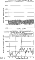
- Figure 4 is a graphical representation of a plot produced by the DVA illustrating measured driveline speed and acceleration for a driveline system under test.
- Figure 5 is a graph similar to Figure 4 of the same driveline after a soft clutch was installed to remedy excessive torsional vibration.
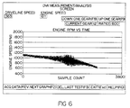
- Figure 6 is a graph produced by the DVA to indicate driveline vibration magnitudes in real time.
- DVA 10 includes a sensor for measuring the rotational speed of a particular driveline component, in the presently preferred embodiment of the invention a magnetic speed sensor 12.
- Sensor 12 is a non-contact magnetic sensor, such as a variable reluctance sensor, which provides speed or timing data in the form of a pulse train.
- sensor 12 is one already present within most modern class 8 truck transmissions, such as transmission 14, to provide a vehicle speedometer signal and is easily reachable from the rear of the transmission.
- An appropriate signal conditioning unit 16 may also be provided to filter and reduce noise in the signal output by sensor 12.
- Sensor 12 provides a clean sixteen pulse per revolution (one pulse for each tooth on a sixteen toothed wheel which rotates with the output shaft of transmission 14) sinusoidal tach signal 18, such as illustrated graphically in Figure 2.
- a signal peak 18a is created by a strong magnetic field occurring as a tooth passes near sensor 12, and a valley 18b is created when the sensor is positioned between passing teeth.
- sensor 12 measures rotational speed or velocity at the output of transmission 14, it is sensitive to all significant driveline torsional excitation sources.
- the transmission output location is typically not the point of highest torsional vibration in the driveline, it has been shown to be sufficiently torsionally active under both engine and universal joint excited vibration to accurately assess driveline torsional behavior.
- any other suitable means could be provided for accurately measuring the rotational speed of a particular driveline component of interest.
- an alternate embodiment may include a similar magnetic sensor adapted to measure the rotational speed between passing teeth of a suitable test fixture affixed for test purposes to the particular driveline component of interest such as an input or output yoke of a vehicle transmission or drive axle.
- An optical sensor could also be used to indicate the passing of markings or indentations made on a particular rotating driveline component.
- Sensor 12 is electrically coupled via a lead 20 to a microprocessor-based electronic control unit (ECU) 22, preferably through signal conditioning unit 16.
- Unit 16 may also be configured to provide power for ECU 22, such as through the vehicle cigar lighter 21.
- ECU 22 may include a personal computer, preferably a portable laptop computer, or any other suitable processor.
- ECU 22 in the present exemplary embodiment is implemented off-board the vehicle in a diagnostic field test application, but with requisite computer power and alternate design choices could alternately be implemented permanently on-board a vehicle as a separate processor or as part of a vehicle's engine or transmission controller.
- ECU 22 includes a high speed continuous period counter board for generating accurate time pulses of uniform frequency to be associated with the measurements obtained by sensor 12. The number of pulses are in effect counted between the sensed passage of each tooth. It can be appreciated that at very high rpms, this information is acquired quite rapidly.
- DVA 10 is able to calculate all driveshaft vibration orders up to one-half of the number of gear teeth. Therefore, DVA 10 is sensitive to U-joint excited torsionals, which are constant second order in all transmission gears.
- Engine excited vibration can be analyzed in all transmission gears up to a maximum gear ratio equal to one-half of the number of teeth multiplied by the engine crankshaft vibration order.
- the fundamental engine firing order for a six cylinder 4-cycle engine is the third crankshaft order.
- DVA 10 could thus analyze engine firing data in all gear ratios less than 2.67. Because engine excited torsionals are of greatest concern in the high range transmission gears, a sixteen tooth gear or wheel is thus adequate.
- the order resolution can be improved by increasing the size of the sample. For example, using the same gear and a sample size of 512, DVA 10 will record 16 shaft rotations and can resolve torsional vibration to the nearest 1/16 order.
- ECU 22 At each rotational order of the crankshaft, ECU 22 produces velocity magnitude data. From this velocity data, displacement and acceleration can also be calculated in a manner well known to those having skill in the art. Details of these calculations are, however, provided in SAE paper No. 942324 entitled “DVA-A New Tool for the Trucking Industry", McGovern et al, presented on November 8, 1994, incorporated herein by reference. These values are preferably formatted and plotted on a suitable display device 24 coupled to, or part of, ECU 22.
- Data obtained at each rotational order of the driveshaft can be compared by ECU 22 to predetermined thresholds, above which torsional vibrations are deemed to be excessive. Measured vibrations above the preset threshold can be indicated visually to the DVA operator through flashing or colored displays 30.
- the acceptable vibration threshold levels can be calculated or determined empirically and most likely will differ with combinations of driveline components.
- DVA 10 is capable of evaluating higher and lower driveline torsional modes within the basic response limitations defined by the maximum vibration order and order resolution as discussed above.
- Second torsional mode typically ranges in frequency from 20-100 Hz, but most commonly occurs between 30-70 Hz in the high range transmission gears.
- the second mode increases in frequency as the transmission numerical gear ratio increases, resulting in the lowest resonant frequency in top gear.
- the resonant vibration amplitude is the highest in top gear and progressively decreases in amplitude for the lower gears.
- the internal combustion engine is the most dominant torsional exciter in the driveline.
- the combustion process produces a dynamic torque waveform which creates oscillatory driveline dynamic torque and torsional displacements.
- the engine dynamic torque waveform is comprised mostly of the fundamental engine firing frequency, but there is also a measurable torque component at the 0.5, 1.5 and 2.0 harmonics of the engine firing frequency.
- firing occurs three times per crankshaft revolution (3rd order).
- the 0.5, 1.5 and 2.0 harmonics would therefore represent the 1.5, 4.5 and 6.0 crankshaft orders, respectively.
- crankshaft orders usually do not present a problem because they are too high in frequency to excite the driveline second torsional mode. However, if the third crankshaft order is coincident in frequency with the second torsional mode, significant resonant amplification can occur and therefore the third order is of particular interest. Similarly, the 1.5 crankshaft order excitation is also a concern because it will be coincident with the resonant frequency at some speed in the primary engine operating range. In some cases, the 1.5 crankshaft order excitation is of sufficient amplitude to create damaging cyclical loading and, therefore is also of interest.
- Torsional effects of non-zero working angles in universal joints will include an oscillatory output rotational speed given a constant input velocity, varying at the rate of two cycles per shaft revolution. Therefore, second order accelerations are also of interest. Significant torsional accelerations in the second order are therefore indicative of non-zero U-joint working angles.
- the drivetrain responds to such torsional excitations by dynamically winding and unwinding. A certain amount of this torsional activity is always present and represents no danger to driveline components. However, if the excitation frequency is coincident with a driveline torsional resonant frequency, serious amplification of driveline torsionals can occur. Excessive universal joint torsionals can cause steady state vibration problems as well as resonant excitation. The steady state problems typically occur at highway cruise speeds and cause excessive driveshaft and component torsional accelerations. If the joint torsionals are sufficient to excite the second torsional mode at the resonant speed, even higher torsional displacements can develop.
- a DVA operator or test technician preferably connects lead 20 to sensor 12.
- the truck can be driven and data logged and stored in a memory device for later use or processed in real time.
- a graph such as that shown in Figure 6 is provided on display 24 in order to indicate in real time to the technician at what speed and in which gears torsional vibrations are most prevalent.
- This real time speed display preferably has sufficient response to indicate torsional activity in real time.
- Figure 6 illustrates the real time display screen for a driveline experiencing engine firing excitation of the second driveline torsional mode. Using this screen, the DVA operator can quickly cycle through each transmission gear under varying operating conditions and loads in search of excessive torsionals (indicated by speed variations which exceed a certain limit). If excessive torsional activity is encountered, the DVA operator can immediately acquire data for further processing. This saves a great deal of time and eliminates the need to obtain large amounts of data at all speeds and gears.
- Driveline torsional activity can be treated in several ways including reducing the amplitude of the excitation source, shifting the resonant speed below the engine's operating range or providing sufficient driveline damping to attenuate torsional response.
- the preferred treatment is dependent upon the nature of the problem.
- DVA 10 By using DVA 10 to identify the source of vibration, the appropriate remedy can be selected.
- Figure 4 illustrates measurements taken from a driveline exhibiting significant fourth order vibration.
- Figure 5 illustrates measurements from the same driveline after appropriate dampening was achieved, with a significant decrease in fourth order vibration. Additional detail concerning this example are provided in the incorporated SAE paper.
- DVA 10 thus provides a convenient and simple solution to many vehicle vibration problems. Sources of vibrations can be pinpointed thereby in order to eliminate expensive and inefficient trial and error driveline repair methods. DVA is configured to allow a vehicle to be tested and the results analyzed in only a couple of hours thereby minimizing vehicle downtime. Additionally, DVA 10 can also be used as an engineering tool to study torsional vibration in vehicle drivelines for use in driveline design as well as input to engine and transmission control algorithms.
Landscapes
- Physics & Mathematics (AREA)
- General Physics & Mathematics (AREA)
- Engineering & Computer Science (AREA)
- Chemical & Material Sciences (AREA)
- Combustion & Propulsion (AREA)
- Transportation (AREA)
- Mechanical Engineering (AREA)
- Measurement Of Mechanical Vibrations Or Ultrasonic Waves (AREA)
- Testing Of Devices, Machine Parts, Or Other Structures Thereof (AREA)
Applications Claiming Priority (2)
| Application Number | Priority Date | Filing Date | Title |
|---|---|---|---|
| US33527594A | 1994-11-07 | 1994-11-07 | |
| US335275 | 1994-11-07 |
Publications (2)
| Publication Number | Publication Date |
|---|---|
| EP0710841A2 true EP0710841A2 (fr) | 1996-05-08 |
| EP0710841A3 EP0710841A3 (fr) | 1998-11-18 |
Family
ID=23311051
Family Applications (1)
| Application Number | Title | Priority Date | Filing Date |
|---|---|---|---|
| EP95117379A Withdrawn EP0710841A3 (fr) | 1994-11-07 | 1995-11-04 | Analyseur de vibrations dans une transmission de véhicule |
Country Status (7)
| Country | Link |
|---|---|
| EP (1) | EP0710841A3 (fr) |
| JP (1) | JPH08219865A (fr) |
| KR (1) | KR100378591B1 (fr) |
| AR (1) | AR000059A1 (fr) |
| AU (1) | AU718968B2 (fr) |
| BR (1) | BR9504922A (fr) |
| CA (1) | CA2162202C (fr) |
Cited By (11)
| Publication number | Priority date | Publication date | Assignee | Title |
|---|---|---|---|---|
| WO1998011479A1 (fr) * | 1996-09-10 | 1998-03-19 | Tektronix, Inc. | Appareil electronique de service apres-vente |
| AT2223U1 (de) * | 1997-07-03 | 1998-06-25 | Avl List Gmbh | Verfahren zur analyse von fahrzeugschwingungen |
| GB2321109A (en) * | 1997-01-13 | 1998-07-15 | Minster Machine Co | Portable press vibration severity monitoring system and method |
| EP0913694A1 (fr) * | 1997-10-31 | 1999-05-06 | Eaton Corporation | Dispositif et procédé d'analyse de vibrations de torsion dans une structure rotative |
| EP0980001A1 (fr) * | 1998-08-13 | 2000-02-16 | Eaton Corporation | Analyseur de vibrations dans une transmission de véhicule |
| EP1039277A1 (fr) * | 1999-03-22 | 2000-09-27 | Meritor Heavy Vehicle Systems, LLC | Système de surveillance de vibration torsionelle |
| GB2365528A (en) * | 2000-03-16 | 2002-02-20 | Ford Global Tech Inc | Method of detecting and correcting vehicle vibration in assembly process |
| US6477451B1 (en) | 1999-11-01 | 2002-11-05 | Meritor Heavy Vehicle Systems, Llc | Method for monitoring the performance of a drive line of a vehicle |
| WO2003038390A1 (fr) * | 2001-10-27 | 2003-05-08 | Vetronix Corporation | Analyseur de bruit, vibrations et rudesse |
| ES2343559A1 (es) * | 2008-02-04 | 2010-08-03 | Universidade Da Coruña | Sensor de velocidad angular y vibraciones torsionales basado en imanes permanentes. |
| US10526934B2 (en) | 2015-09-25 | 2020-01-07 | Eaton Intelligent Power Limited | Cylinder deactivation control and methods |
Families Citing this family (2)
| Publication number | Priority date | Publication date | Assignee | Title |
|---|---|---|---|---|
| KR101633972B1 (ko) * | 2014-04-28 | 2016-06-27 | 한국수력원자력 주식회사 | 비틀림 진동의 진단 및 평가 장치와 그 방법 |
| JP7338584B2 (ja) * | 2020-08-07 | 2023-09-05 | トヨタ自動車株式会社 | 異常判定装置 |
Family Cites Families (2)
| Publication number | Priority date | Publication date | Assignee | Title |
|---|---|---|---|---|
| US4148222A (en) * | 1977-12-22 | 1979-04-10 | General Electric Company | Apparatus and method for measuring torsional vibration |
| CH674398A5 (fr) * | 1986-06-23 | 1990-05-31 | Sulzer Ag |
-
1995
- 1995-11-02 AR AR33408695A patent/AR000059A1/es unknown
- 1995-11-04 EP EP95117379A patent/EP0710841A3/fr not_active Withdrawn
- 1995-11-06 CA CA002162202A patent/CA2162202C/fr not_active Expired - Fee Related
- 1995-11-06 KR KR1019950039979A patent/KR100378591B1/ko not_active Expired - Fee Related
- 1995-11-06 AU AU37701/95A patent/AU718968B2/en not_active Ceased
- 1995-11-07 BR BR9504922A patent/BR9504922A/pt not_active Application Discontinuation
- 1995-11-07 JP JP7288555A patent/JPH08219865A/ja active Pending
Cited By (20)
| Publication number | Priority date | Publication date | Assignee | Title |
|---|---|---|---|---|
| WO1998011479A1 (fr) * | 1996-09-10 | 1998-03-19 | Tektronix, Inc. | Appareil electronique de service apres-vente |
| GB2321109A (en) * | 1997-01-13 | 1998-07-15 | Minster Machine Co | Portable press vibration severity monitoring system and method |
| FR2758391A1 (fr) * | 1997-01-13 | 1998-07-17 | Minster Machine Co | Dispositif et procede de surveillance de la violence des vibrations dans une presse portative |
| GB2321109B (en) * | 1997-01-13 | 2001-03-28 | Minster Machine Co | Portable Press Vibration Severity Monitoring system and method |
| US6209400B1 (en) | 1997-01-13 | 2001-04-03 | The Minster Machine Company | Portable press vibration severity monitoring system and method |
| AT2223U1 (de) * | 1997-07-03 | 1998-06-25 | Avl List Gmbh | Verfahren zur analyse von fahrzeugschwingungen |
| EP0913694A1 (fr) * | 1997-10-31 | 1999-05-06 | Eaton Corporation | Dispositif et procédé d'analyse de vibrations de torsion dans une structure rotative |
| EP0980001A1 (fr) * | 1998-08-13 | 2000-02-16 | Eaton Corporation | Analyseur de vibrations dans une transmission de véhicule |
| EP1039277A1 (fr) * | 1999-03-22 | 2000-09-27 | Meritor Heavy Vehicle Systems, LLC | Système de surveillance de vibration torsionelle |
| US6477451B1 (en) | 1999-11-01 | 2002-11-05 | Meritor Heavy Vehicle Systems, Llc | Method for monitoring the performance of a drive line of a vehicle |
| GB2365528A (en) * | 2000-03-16 | 2002-02-20 | Ford Global Tech Inc | Method of detecting and correcting vehicle vibration in assembly process |
| US6481271B1 (en) | 2000-03-16 | 2002-11-19 | Ford Motor Company | Method to correct vehicle vibration during an assembly process |
| GB2365528B (en) * | 2000-03-16 | 2003-11-12 | Ford Global Tech Inc | Method to correct vehicle vibration during an assembly process |
| WO2003038390A1 (fr) * | 2001-10-27 | 2003-05-08 | Vetronix Corporation | Analyseur de bruit, vibrations et rudesse |
| ES2343559A1 (es) * | 2008-02-04 | 2010-08-03 | Universidade Da Coruña | Sensor de velocidad angular y vibraciones torsionales basado en imanes permanentes. |
| ES2343559B1 (es) * | 2008-02-04 | 2011-04-08 | Universidade Da Coruña | Sensor de velocidad angular y vibraciones torsionales basado en imanes permanentes. |
| US10526934B2 (en) | 2015-09-25 | 2020-01-07 | Eaton Intelligent Power Limited | Cylinder deactivation control and methods |
| US10563549B2 (en) | 2015-09-25 | 2020-02-18 | Eaton Intelligent Power Limited | Cylinder deactivation control and methods |
| US10619525B2 (en) | 2015-09-25 | 2020-04-14 | Eaton Intelligent Power Limited | Cylinder deactivation hydraulic lash adjuster |
| US11459917B2 (en) | 2015-09-25 | 2022-10-04 | Eaton Intelligent Power Limited | Cylinder deactivation energy waste management |
Also Published As
| Publication number | Publication date |
|---|---|
| EP0710841A3 (fr) | 1998-11-18 |
| CA2162202A1 (fr) | 1996-05-08 |
| KR100378591B1 (ko) | 2003-06-02 |
| BR9504922A (pt) | 1997-09-02 |
| CA2162202C (fr) | 2003-03-18 |
| AU3770195A (en) | 1996-05-16 |
| KR960018533A (ko) | 1996-06-17 |
| AU718968B2 (en) | 2000-05-04 |
| AR000059A1 (es) | 1997-05-21 |
| JPH08219865A (ja) | 1996-08-30 |
Similar Documents
| Publication | Publication Date | Title |
|---|---|---|
| US6128959A (en) | Driveline vibration analyzer | |
| US5955674A (en) | Driveline vibration system diagnostics | |
| US6729186B1 (en) | Multi-channel vibration analyzer | |
| US7487679B2 (en) | Vehicle vibration analyzer | |
| US5390545A (en) | Apparatus for measuring torsional vibrations of rotating machinery | |
| EP0710841A2 (fr) | Analyseur de vibrations dans une transmission de véhicule | |
| CN102072818B (zh) | 转速传感器前置时获取发动机各缸失火检测信号的方法 | |
| US8935041B2 (en) | Diagnostic method for a torsional damper in a drive train of a vehicle | |
| JPH09503270A (ja) | 改善された信号忠実度を備えた加速度をベースとした不点火検出システムおよび方法 | |
| Barthod et al. | Experimental study of gear rattle excited by a multi-harmonic excitation | |
| Barthod et al. | Experimental study of dynamic and noise produced by a gearing excited by a multi-harmonic excitation | |
| KR910010172A (ko) | 엔진에 접속된 자동차 동력 전달부의 시험편을 검사하고 동력계를 사용하여 검사된 시험편을 통해 엔진 출력 특성을 분석하기 위한 방법 및 시스템 | |
| JP3036237B2 (ja) | トランスミッション試験装置 | |
| EP1815221B1 (fr) | Procede de determination d un couple moteur moyen | |
| MXPA99007456A (en) | Tracc line vibration analyzer | |
| RU2219510C2 (ru) | Способ испытания дизельных двигателей | |
| Shih et al. | Drivetrain noise and vibration troubleshooting | |
| McGovern et al. | DVA-A new tool for the trucking industry | |
| KONDO et al. | Abnormality detection for auxiliary drive shafts on diesel cars using vibration condition monitoring | |
| KR20010059037A (ko) | 차량의 변속기 소음/진동 발생 근접 방법 | |
| Karlsson | Investigation of Dynamic Friction Properties of a Dual Mass Flywheel for Commercial Vehicles | |
| Parshall | Torsional Vibration Analysis and Algorithm-Based Control for Driveline Reliability in Trucks | |
| Parshall et al. | Real-time detection of linear and nonlinear resonance modes in automatic transmission driveline: A novel algorithm for enhanced reliability | |
| Kelm et al. | Analysis of transversal belt vibrations in passenger car accessory drives | |
| Gul et al. | Modeling and torsional vibration analysis of engine cold-test stand drivelines |
Legal Events
| Date | Code | Title | Description |
|---|---|---|---|
| PUAI | Public reference made under article 153(3) epc to a published international application that has entered the european phase |
Free format text: ORIGINAL CODE: 0009012 |
|
| AK | Designated contracting states |
Kind code of ref document: A2 Designated state(s): DE ES FR GB IT SE |
|
| RAP1 | Party data changed (applicant data changed or rights of an application transferred) |
Owner name: DANA CORPORATION |
|
| PUAL | Search report despatched |
Free format text: ORIGINAL CODE: 0009013 |
|
| AK | Designated contracting states |
Kind code of ref document: A3 Designated state(s): DE ES FR GB IT SE |
|
| 17P | Request for examination filed |
Effective date: 19990510 |
|
| RAP1 | Party data changed (applicant data changed or rights of an application transferred) |
Owner name: EATON CORPORATION |
|
| 17Q | First examination report despatched |
Effective date: 20000317 |
|
| STAA | Information on the status of an ep patent application or granted ep patent |
Free format text: STATUS: THE APPLICATION IS DEEMED TO BE WITHDRAWN |
|
| 18D | Application deemed to be withdrawn |
Effective date: 20011227 |