EP0710904A1 - Système de contrÔle backplane pour machine à filer - Google Patents
Système de contrÔle backplane pour machine à filer Download PDFInfo
- Publication number
- EP0710904A1 EP0710904A1 EP94116825A EP94116825A EP0710904A1 EP 0710904 A1 EP0710904 A1 EP 0710904A1 EP 94116825 A EP94116825 A EP 94116825A EP 94116825 A EP94116825 A EP 94116825A EP 0710904 A1 EP0710904 A1 EP 0710904A1
- Authority
- EP
- European Patent Office
- Prior art keywords
- level
- bus
- communication
- network
- spinning
- Prior art date
- Legal status (The legal status is an assumption and is not a legal conclusion. Google has not performed a legal analysis and makes no representation as to the accuracy of the status listed.)
- Granted
Links
Images

Classifications
-
- D—TEXTILES; PAPER
- D01—NATURAL OR MAN-MADE THREADS OR FIBRES; SPINNING
- D01H—SPINNING OR TWISTING
- D01H13/00—Other common constructional features, details or accessories
- D01H13/32—Counting, measuring, recording or registering devices
-
- D—TEXTILES; PAPER
- D01—NATURAL OR MAN-MADE THREADS OR FIBRES; SPINNING
- D01H—SPINNING OR TWISTING
- D01H1/00—Spinning or twisting machines in which the product is wound-up continuously
- D01H1/14—Details
- D01H1/20—Driving or stopping arrangements
- D01H1/32—Driving or stopping arrangements for complete machines
-
- D—TEXTILES; PAPER
- D01—NATURAL OR MAN-MADE THREADS OR FIBRES; SPINNING
- D01H—SPINNING OR TWISTING
- D01H4/00—Open-end spinning machines or arrangements for imparting twist to independently moving fibres separated from slivers; Piecing arrangements therefor; Covering endless core threads with fibres by open-end spinning techniques
- D01H4/42—Control of driving or stopping
-
- G—PHYSICS
- G05—CONTROLLING; REGULATING
- G05B—CONTROL OR REGULATING SYSTEMS IN GENERAL; FUNCTIONAL ELEMENTS OF SUCH SYSTEMS; MONITORING OR TESTING ARRANGEMENTS FOR SUCH SYSTEMS OR ELEMENTS
- G05B19/00—Program-control systems
- G05B19/02—Program-control systems electric
- G05B19/418—Total factory control, i.e. centrally controlling a plurality of machines, e.g. direct or distributed numerical control [DNC], flexible manufacturing systems [FMS], integrated manufacturing systems [IMS] or computer integrated manufacturing [CIM]
- G05B19/4185—Total factory control, i.e. centrally controlling a plurality of machines, e.g. direct or distributed numerical control [DNC], flexible manufacturing systems [FMS], integrated manufacturing systems [IMS] or computer integrated manufacturing [CIM] characterised by the network communication
-
- G—PHYSICS
- G05—CONTROLLING; REGULATING
- G05B—CONTROL OR REGULATING SYSTEMS IN GENERAL; FUNCTIONAL ELEMENTS OF SUCH SYSTEMS; MONITORING OR TESTING ARRANGEMENTS FOR SUCH SYSTEMS OR ELEMENTS
- G05B2219/00—Program-control systems
- G05B2219/30—Nc systems
- G05B2219/31—From computer integrated manufacturing till monitoring
- G05B2219/31145—Ethernet
-
- G—PHYSICS
- G05—CONTROLLING; REGULATING
- G05B—CONTROL OR REGULATING SYSTEMS IN GENERAL; FUNCTIONAL ELEMENTS OF SUCH SYSTEMS; MONITORING OR TESTING ARRANGEMENTS FOR SUCH SYSTEMS OR ELEMENTS
- G05B2219/00—Program-control systems
- G05B2219/30—Nc systems
- G05B2219/31—From computer integrated manufacturing till monitoring
- G05B2219/31186—TCP-IP internet protocol
-
- G—PHYSICS
- G05—CONTROLLING; REGULATING
- G05B—CONTROL OR REGULATING SYSTEMS IN GENERAL; FUNCTIONAL ELEMENTS OF SUCH SYSTEMS; MONITORING OR TESTING ARRANGEMENTS FOR SUCH SYSTEMS OR ELEMENTS
- G05B2219/00—Program-control systems
- G05B2219/30—Nc systems
- G05B2219/31—From computer integrated manufacturing till monitoring
- G05B2219/31234—Host, router and backplane bus, communication with host or backplane
-
- G—PHYSICS
- G05—CONTROLLING; REGULATING
- G05B—CONTROL OR REGULATING SYSTEMS IN GENERAL; FUNCTIONAL ELEMENTS OF SUCH SYSTEMS; MONITORING OR TESTING ARRANGEMENTS FOR SUCH SYSTEMS OR ELEMENTS
- G05B2219/00—Program-control systems
- G05B2219/30—Nc systems
- G05B2219/33—Director till display
- G05B2219/33169—Name of bus, vme-bus
-
- G—PHYSICS
- G05—CONTROLLING; REGULATING
- G05B—CONTROL OR REGULATING SYSTEMS IN GENERAL; FUNCTIONAL ELEMENTS OF SUCH SYSTEMS; MONITORING OR TESTING ARRANGEMENTS FOR SUCH SYSTEMS OR ELEMENTS
- G05B2219/00—Program-control systems
- G05B2219/30—Nc systems
- G05B2219/45—Nc applications
- G05B2219/45191—Spinning, web spinning
-
- Y—GENERAL TAGGING OF NEW TECHNOLOGICAL DEVELOPMENTS; GENERAL TAGGING OF CROSS-SECTIONAL TECHNOLOGIES SPANNING OVER SEVERAL SECTIONS OF THE IPC; TECHNICAL SUBJECTS COVERED BY FORMER USPC CROSS-REFERENCE ART COLLECTIONS [XRACs] AND DIGESTS
- Y02—TECHNOLOGIES OR APPLICATIONS FOR MITIGATION OR ADAPTATION AGAINST CLIMATE CHANGE
- Y02P—CLIMATE CHANGE MITIGATION TECHNOLOGIES IN THE PRODUCTION OR PROCESSING OF GOODS
- Y02P90/00—Enabling technologies with a potential contribution to greenhouse gas [GHG] emissions mitigation
- Y02P90/02—Total factory control, e.g. smart factories, flexible manufacturing systems [FMS] or integrated manufacturing systems [IMS]
Definitions
- the technical field of the invention is the spinning machines and there a method for controlling a group of spinning machines consisting of several spinning machines (“spinning machine group”) and a control network for establishing a system control of the spinning machine group.
- a spinning machine consists of a large number of spinning stations, currently around 280 spinning stations are combined into one spinning machine. For many applications, however, it is necessary to interconnect several spinning machines, with the control center being given considerable weight. Assuming the R1 spinning machine from Rieter AG in accordance with brochure 1431 d from November 1992, up to 32 rotor spinning machines can be connected to the SCC II control center there. Each of these rotor spinning machines can have up to 280 spinning positions. This shows the complexity and size of such a system if several machine groups of the size mentioned are connected together in large spinning mills to form a large network.
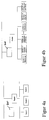
- FIGS. 4a, 4b Examples of possible networks in the prior art are FIGS. 4a, 4b , in which two topologies are represented graphically in a simplified manner. These topologies work with the network Ethernet, the protocol is the art and CSMA / CD (ense C arrier S Multiple Access with C Olli sion D etect) is called. It works in such a way that a station (a "node”) sends a data or information packet if it has previously checked whether another node is already active. If another node (node or station) is active, the first one waits until the network cable is free.
- CSMA / CD sense C arrier S Multiple Access with C Olli sion D etect
- Node 1 and Node 2 or Node 1.1 and Node 1.2 blocks the network for all other stations that do not do this during the communication of two stations Network.
- the "router” shown (communication from the lower network to the higher network in FIG. 4b), to which the host (also several hosts) is coupled, also loads the network.
- the invention proposes the data communication protocol for the exchange and transmission of operating data and measured values higher communication level to use at the lower communication level (claim 1).
- a bus backplane (claim 7) on which several components, in particular several CPUs (central processing units) are coupled to one another.
- a bus backplane can represent a spinning machine with its large number of spinning stations (claim 13).
- Data communication enables improved control of the machine group; Communication can easily be used to monitor the machine group.
- bus backplane is not tied to a specific architecture, bus backplanes from Intel (Multibus I, II) or Motorola (VME) or others can be used.
- the bus backplane is closely related to the machine control on the one hand and closely related to the network on the other.
- the close coupling due to the hardware structure is supported by the selected software coupling, in which the communication protocol on the bus backplane and the communication protocol on the higher communication level are the same, in particular a standardized protocol (claim 2, claim 13).
- the bus system with the backplane can accommodate various types of interface circuits (interfaces).
- a non-deterministic bus is brought very close to the spinning machine, and in terms of hardware technology as close as a conventional network (e.g. according to the Ethernet principle) would not suffice.
- the spinning machine must also be able to perform deterministic tasks that are time-critical.
- corresponding processors are coupled to the bus backplane, which enable deterministic controls and regulation and the equidistant acquisition of samples.
- the bus backplane is therefore advantageously constructed as a multiprocessor bus backplane (claim 3). If a multiprocessor bus backplane is used, the associated standard protocol is also multiprocessor capable (claim 2.6), e.g. it corresponds to the TCP / IP protocol.
- the bus backplanes which can each be assigned to a spinning machine, can be interconnected in a local network, so that a first group of spinning machines is coupled to one another via this local bus (claim 13).
- Several of the local buses can be coupled to a higher-level network via respective routers (claim 14), so that a main controller (host) has access via respective routers to respective subnetworks (“subnets”), which in turn structures into several bus backplanes are.
- the bus backplane and subnet have the same topology (read: the same data communication protocol), which speeds up communication considerably and structurally simplifies it.
- a network design that is sufficient for most network controls of spinning machines consists of three levels, level j, level j + 1 and level j + 2.
- Level j is that of the bus backplanes.
- Several bus backplanes BPi are included here and switched to a local bus consisting of a cable via network access.
- the local bus is the higher level j + 1.
- the data communication protocol at level j + 1 and that in the bus backplanes BPi - level j - is the same.
- a router leads from level j + 1 to a higher level j + 2, to which the central control - the "host" - is coupled.
- the level of the bus backplanes there are three levels, the level of the bus backplanes, the level of the local bus, which is the higher-level bus, and the level of the host, which is coupled to the higher-level bus.
- the same data communication protocol does not exist between the higher level j + 2 and the level j + 1 immediately below it; protocol identity only exists between level j + 1 and the level below - level j of the bus backplanes.
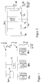
- FIG. 2 picks out a bus backplane from FIG. 1, the BP1, which contains an access module C1, which gives the bus backplane access to the network-oriented bus of level j + 1 (or in a further exemplary embodiment to the this higher-level bus of level j + 2).
- FIG. 3 illustrates a schematic view of a VME bus backplane, which is coupled down to an AT bus via a processor (a CPU) and which is connected upwards via VCOM to the local TCP / IP bus of level j + 1 of FIG. 1 can access.
- the BP1 is representative of a single machine, for example with 280 spinning positions. The communication level depicted is thus “inside the spinning machine", while the couplings to the outside (to the local bus) and to the other central units are "considered outside the machine”.
- FIG. 1 illustrates an exemplary combination of three bus backplanes BP1, BP2, BP3, which are interconnected on a local bus (level j + 1).
- a router R leads from the local bus to a higher-level bus, which is labeled "level j + 2" in FIG.
- a host system M is connected to it, which takes over the central administration of all routers R potentially coupled to the higher-level bus at level j + 2.
- the multiple routers R can result in an expanded system by supplementing the 4 components R, BP1, BP2, BP3 on the higher-level bus j + 2.
- the system of FIG. 1 is not limited to this extent.
- the system is also not limited in the number of BPi backplanes connected to the local bus of level j + 1, there can be a large number of these backplanes are connected there. However, all of these backplanes have the same data communication protocol that was selected in the example for TCP / IP. UDP / IP is also possible.
- backplane 1 is selected as an example. It shows that several central processing units (CPU) are connected to the backplane, in the example in FIG. 2 there are three CPUs P1, P2 and P3. One of these CPUs, here the CPU P1, is connected via the backplane BP1 to the Ethernet controller C1, which couples the backplane BP1 at the network level.
- the level j + 1 of FIG. 1 lying directly (logistically) above the backplane BP1 can be used as the network level;
- the level j + 2 of FIG. 1 can also be used as the level, which can be directly coupled to the backplane BP1 via a corresponding controller C.
- Both the one coupling and both couplings can be switched depending on the respective application; if both couplings are used, two network control devices (Ethernet controllers) C are used, one couples the backplane BP1 to the level j + 2, the other couples the backplane BP1 to the level j + 1.
- Ethernet controllers Ethernet controllers
- the backplane BP1 is schematically a hardware data bus and an address bus with an associated number of control lines. Overall, it is referred to as bus B1.
- each backplane BPi can contain a plurality of central units Pk, where k represents integers from 1 to p; p is therefore representative of a multiprocessor system that is installed on a backplane.
- a backplane is understood to be such a circuit board which has a plurality of layers in which the slots arranged on it are connected to lines. It can roughly be compared with a typical AT bus plate, which, however, is not multiprocessor-compatible, like the backplane BP of FIGS. 1 and 2. Only because of the multiprocessor capability is it possible for the communication protocol on the network of level j + 1 to be the communication protocol on the backplane.
- FIGS. 4a and 4b represent exemplary embodiments of the invention
- circuits of the prior art are explained in FIGS. 4a and 4b.
- FIG. 4a it was already explained at the beginning why this topology is time-consuming, collision-prone and not very structured.
- the network topology of FIG. 4b which would be a possible alternative to that of FIG. 4a, leaves unsettled responsibilities and unpredictable load problems between the individual functional units (referred to as node 1.1 to node n.3). This results from the fact that many functional units (nodes) do not come from the same manufacturer and are therefore constructed differently.
- Each of these nodes can have a different architecture, so that there are no similarities in the common network bus, which leads via the router to the host system, unless each of the systems would receive a correspondingly adapted network coupling card.
- This coupling card slows down the system and increases the likelihood of collisions, especially when the nodes 1.1, 1.2 and 1.3 belonging to, for example, a machine communicate with one another, the entire remaining bus being functionally blocked.
- FIG. 3 schematically realizes the backplane BP1 of FIG. 2 using a VME bus.
- a PC 80386 SX coupling card forms a connection in an AT bus, which is deterministic.
- the plug-in card VCOM forms the coupling C1 of FIG. 2, which leads from the backplane BP1 to the local bus of level j + 1 of FIG. 1.
- the local bus is that of level j + 1, not that of the backplane BP1.
- This bus is located on level j, one level below network level j + 1.
- Superordinate to the first network level j + 1 is level j + 2, which cannot be seen in FIG. 3, but which can be seen when several VCOMs are interconnected at network level j + 1 and a router R is local to them
- Bus j + 1 couples to the higher-level bus j + 2.
- VCOM of FIG. 3 represents the CPU P1 of FIG. 2 in the sketch of FIG. 3, as a direct router R to the higher-level bus of level j + 2.
- the router R is then physically contained in two separate cards, VM30 and VCOM.
Landscapes
- Engineering & Computer Science (AREA)
- Mechanical Engineering (AREA)
- Textile Engineering (AREA)
- General Engineering & Computer Science (AREA)
- Manufacturing & Machinery (AREA)
- Quality & Reliability (AREA)
- Physics & Mathematics (AREA)
- General Physics & Mathematics (AREA)
- Automation & Control Theory (AREA)
- Small-Scale Networks (AREA)
- Preliminary Treatment Of Fibers (AREA)
- Spinning Or Twisting Of Yarns (AREA)
- Selective Calling Equipment (AREA)
Priority Applications (7)
| Application Number | Priority Date | Filing Date | Title |
|---|---|---|---|
| EP94116825A EP0710904B1 (fr) | 1994-10-25 | 1994-10-25 | Système de contrÔle backplane pour machine à filer |
| DE59407059T DE59407059D1 (de) | 1994-10-25 | 1994-10-25 | Backplane-Steuerung für Spinnereimaschine |
| US08/467,165 US5710708A (en) | 1994-10-25 | 1995-06-06 | Backplane control system for spinning machines |
| JP7244279A JPH08289377A (ja) | 1994-10-25 | 1995-09-22 | 紡績機械群を制御するための方法、及びそのシステム制御を構成するための制御ネットワ−ク |
| IT95MI002164A IT1276971B1 (it) | 1994-10-25 | 1995-10-20 | Comando a retroquadri per macchine di filatura |
| DE19539354A DE19539354A1 (de) | 1994-10-25 | 1995-10-23 | Backplane-Steuerung für Spinnereimaschine |
| CZ952786A CZ278695A3 (en) | 1994-10-25 | 1995-10-25 | Method of controlling a group of spinning machines and a control network for making the same |
Applications Claiming Priority (1)
| Application Number | Priority Date | Filing Date | Title |
|---|---|---|---|
| EP94116825A EP0710904B1 (fr) | 1994-10-25 | 1994-10-25 | Système de contrÔle backplane pour machine à filer |
Publications (2)
| Publication Number | Publication Date |
|---|---|
| EP0710904A1 true EP0710904A1 (fr) | 1996-05-08 |
| EP0710904B1 EP0710904B1 (fr) | 1998-10-07 |
Family
ID=8216409
Family Applications (1)
| Application Number | Title | Priority Date | Filing Date |
|---|---|---|---|
| EP94116825A Revoked EP0710904B1 (fr) | 1994-10-25 | 1994-10-25 | Système de contrÔle backplane pour machine à filer |
Country Status (6)
| Country | Link |
|---|---|
| US (1) | US5710708A (fr) |
| EP (1) | EP0710904B1 (fr) |
| JP (1) | JPH08289377A (fr) |
| CZ (1) | CZ278695A3 (fr) |
| DE (2) | DE59407059D1 (fr) |
| IT (1) | IT1276971B1 (fr) |
Cited By (2)
| Publication number | Priority date | Publication date | Assignee | Title |
|---|---|---|---|---|
| WO1999013388A1 (fr) * | 1997-09-10 | 1999-03-18 | Square D Company | Appareil de gestion des communications interreseau |
| EP1340128B1 (fr) * | 2000-12-05 | 2007-01-31 | Hirschmann Electronics GmbH & Co. KG | Distribution de donnees |
Families Citing this family (41)
| Publication number | Priority date | Publication date | Assignee | Title |
|---|---|---|---|---|
| US7630861B2 (en) * | 1996-03-28 | 2009-12-08 | Rosemount Inc. | Dedicated process diagnostic device |
| US7254518B2 (en) | 1996-03-28 | 2007-08-07 | Rosemount Inc. | Pressure transmitter with diagnostics |
| US8290721B2 (en) * | 1996-03-28 | 2012-10-16 | Rosemount Inc. | Flow measurement diagnostics |
| US7623932B2 (en) | 1996-03-28 | 2009-11-24 | Fisher-Rosemount Systems, Inc. | Rule set for root cause diagnostics |
| US7949495B2 (en) * | 1996-03-28 | 2011-05-24 | Rosemount, Inc. | Process variable transmitter with diagnostics |
| JP3722399B2 (ja) * | 1997-05-26 | 2005-11-30 | 東レエンジニアリング株式会社 | 糸条製造工程における張力監視方法 |
| US6587884B1 (en) * | 1997-09-10 | 2003-07-01 | Schneider Automation, Inc. | Dual ethernet protocol stack for maximum speed access to a programmable logic controller (PLC) |
| CN1177266C (zh) | 1997-10-13 | 2004-11-24 | 罗斯蒙德公司 | 工业过程中现场的过程设备及其形成方法 |
| US7010459B2 (en) * | 1999-06-25 | 2006-03-07 | Rosemount Inc. | Process device diagnostics using process variable sensor signal |
| DE19954258A1 (de) * | 1999-11-11 | 2001-05-17 | Truetzschler Gmbh & Co Kg | Vorrichtung zur elektronischen Steuerung von Spinnereimaschinen, insbesondere Spinnereivorbereitungsmaschinen |
| DE20004400U1 (de) * | 2000-03-09 | 2001-07-19 | Cooper Power Tools GmbH & Co., 73463 Westhausen | Betriebsnetzwerksystem |
| FR2811844B1 (fr) * | 2000-07-13 | 2002-11-29 | Schneider Automation S A | Bus interne automate supportant le protocole tcp/ip |
| US6671583B2 (en) | 2001-03-30 | 2003-12-30 | Helix Technology Corporation | Vacuum system information network |
| US6629059B2 (en) | 2001-05-14 | 2003-09-30 | Fisher-Rosemount Systems, Inc. | Hand held diagnostic and communication device with automatic bus detection |
| RU2324171C2 (ru) * | 2003-07-18 | 2008-05-10 | Роузмаунт Инк. | Диагностика процесса |
| US7018800B2 (en) * | 2003-08-07 | 2006-03-28 | Rosemount Inc. | Process device with quiescent current diagnostics |
| US7627441B2 (en) * | 2003-09-30 | 2009-12-01 | Rosemount Inc. | Process device with vibration based diagnostics |
| US7523667B2 (en) * | 2003-12-23 | 2009-04-28 | Rosemount Inc. | Diagnostics of impulse piping in an industrial process |
| US6920799B1 (en) | 2004-04-15 | 2005-07-26 | Rosemount Inc. | Magnetic flow meter with reference electrode |
| US7046180B2 (en) | 2004-04-21 | 2006-05-16 | Rosemount Inc. | Analog-to-digital converter with range error detection |
| US8112565B2 (en) * | 2005-06-08 | 2012-02-07 | Fisher-Rosemount Systems, Inc. | Multi-protocol field device interface with automatic bus detection |
| US7835295B2 (en) | 2005-07-19 | 2010-11-16 | Rosemount Inc. | Interface module with power over Ethernet function |
| DE102005044733A1 (de) * | 2005-09-19 | 2007-03-22 | Maschinenfabrik Rieter Ag | Steuerung für Spinnmaschinen |
| US20070068225A1 (en) * | 2005-09-29 | 2007-03-29 | Brown Gregory C | Leak detector for process valve |
| US7953501B2 (en) | 2006-09-25 | 2011-05-31 | Fisher-Rosemount Systems, Inc. | Industrial process control loop monitor |
| JP2010505121A (ja) | 2006-09-29 | 2010-02-18 | ローズマウント インコーポレイテッド | 検証を備える磁気流量計 |
| US7321846B1 (en) | 2006-10-05 | 2008-01-22 | Rosemount Inc. | Two-wire process control loop diagnostics |
| EP1935577A1 (fr) * | 2006-12-21 | 2008-06-25 | Abb Ab | Système de commande pour contrôler un robot industriel |
| DE102007032237A1 (de) * | 2007-07-11 | 2009-01-15 | Rieter Ingolstadt Gmbh | Textilmaschine |
| US8898036B2 (en) * | 2007-08-06 | 2014-11-25 | Rosemount Inc. | Process variable transmitter with acceleration sensor |
| US7590511B2 (en) * | 2007-09-25 | 2009-09-15 | Rosemount Inc. | Field device for digital process control loop diagnostics |
| DE102007052677B4 (de) * | 2007-11-05 | 2016-04-21 | Saurer Germany Gmbh & Co. Kg | Verfahren zum Betreiben einer eine Vielzahl von Arbeitsstellen aufweisenden Textilmaschine |
| DE102009057273A1 (de) * | 2009-12-08 | 2011-06-09 | Diehl Bgt Defence Gmbh & Co. Kg | Elektronische Baugruppe |
| US9207670B2 (en) | 2011-03-21 | 2015-12-08 | Rosemount Inc. | Degrading sensor detection implemented within a transmitter |
| JP2013067473A (ja) * | 2011-09-21 | 2013-04-18 | Murata Machinery Ltd | 糸巻取機 |
| US9052240B2 (en) | 2012-06-29 | 2015-06-09 | Rosemount Inc. | Industrial process temperature transmitter with sensor stress diagnostics |
| US9602122B2 (en) | 2012-09-28 | 2017-03-21 | Rosemount Inc. | Process variable measurement noise diagnostic |
| DE102012109669A1 (de) * | 2012-10-11 | 2014-05-15 | Rieter Ingolstadt Gmbh | Textilmaschine, insbesondere Spinnmaschine oder Spulmaschine, mit einem Steuer- und Kommunikationssystem |
| CN104345694A (zh) * | 2013-07-30 | 2015-02-11 | 新安乃达驱动技术(上海)有限公司 | 细纱机纺纱控制系统 |
| KR101534433B1 (ko) * | 2014-02-03 | 2015-07-06 | 영남대학교 산학협력단 | 방적기 제어장치 |
| EA037819B1 (ru) | 2014-07-31 | 2021-05-25 | Камоцци Диджитал С.Р.Л. | Способ контроля физических параметров текстильного оборудования |
Citations (1)
| Publication number | Priority date | Publication date | Assignee | Title |
|---|---|---|---|---|
| EP0135881A2 (fr) * | 1983-09-19 | 1985-04-03 | Siemens Aktiengesellschaft | Appareil d'automatisation programmable à mémoire |
Family Cites Families (8)
| Publication number | Priority date | Publication date | Assignee | Title |
|---|---|---|---|---|
| US4835699A (en) * | 1987-03-23 | 1989-05-30 | Burlington Industries, Inc. | Automated distributed control system for a weaving mill |
| JP2834122B2 (ja) * | 1987-07-08 | 1998-12-09 | 株式会社日立製作所 | 制御装置 |
| DE3924779A1 (de) * | 1989-07-26 | 1991-01-31 | Rieter Ag Maschf | Verfahren und vorrichtung zum betrieb einer spinnereilinie |
| GB9006661D0 (en) * | 1990-03-24 | 1990-05-23 | Reflex Manufacturing Systems L | Network-field interface for manufacturing systems |
| JPH047269A (ja) * | 1990-04-24 | 1992-01-10 | Murata Mach Ltd | 紡績工場における品質管理システム |
| IT1246039B (it) * | 1990-07-10 | 1994-11-07 | Tiziano Barea | Disopositivo per il controllo del funzionamento di macchine in particolare di macchine tessili in grado di autoapprendere il ciclo operativo di queste ultime e di correggere i propi errori in tale fase di autoapprendimento |
| US5517404A (en) * | 1991-01-23 | 1996-05-14 | Biber; Heinz | Process control in the textile plant |
| DE69316009T2 (de) * | 1992-06-12 | 1998-04-23 | Dow Benelux | Sicheres frontendverbindungssystem und verfahren fur prozesssteuerungsrechner |
-
1994
- 1994-10-25 EP EP94116825A patent/EP0710904B1/fr not_active Revoked
- 1994-10-25 DE DE59407059T patent/DE59407059D1/de not_active Revoked
-
1995
- 1995-06-06 US US08/467,165 patent/US5710708A/en not_active Expired - Fee Related
- 1995-09-22 JP JP7244279A patent/JPH08289377A/ja active Pending
- 1995-10-20 IT IT95MI002164A patent/IT1276971B1/it active IP Right Grant
- 1995-10-23 DE DE19539354A patent/DE19539354A1/de not_active Withdrawn
- 1995-10-25 CZ CZ952786A patent/CZ278695A3/cs unknown
Patent Citations (1)
| Publication number | Priority date | Publication date | Assignee | Title |
|---|---|---|---|---|
| EP0135881A2 (fr) * | 1983-09-19 | 1985-04-03 | Siemens Aktiengesellschaft | Appareil d'automatisation programmable à mémoire |
Non-Patent Citations (8)
| Title |
|---|
| J.-D. DECOTIGNIE: "Integrating the Numerical Controller and the FMS", 15TH ANNUAL CONFERENCE OF IEEE INDUSTRIAL ELECTRONICS SOCIETY, VOLUME I - POWER ELECTRONICS, 6 November 1989 (1989-11-06), PHILADELPHIA, USA, pages 675 - 680, XP000130574 * |
| KOZIOL ET AL.: "CIE INTEGRATED SYSTEM FOR THE CPCM (COUPLED PICKLE LINE AND TANDEM COLD MILL) AT DOFASCO'S HAMILTON WORKS", CONFERENCE RECORD OF THE 1993 IEEE INDUSTRY APPLICATIONS CONFERENCE TWENTY-EIGHTH IAS ANNUAL MEETING, PART III, 3 October 1993 (1993-10-03), TORONTO, CANADA, pages 2388 - 2392, XP000420464 * |
| LARS-BERNO FREDRIKSSON: "CONTROLLER AREA NETWORKS AND THE PROTOCOL CAN FOR MACHINE CONTROL SYSTEMS", MECHATRONICS, vol. 4, no. 2, March 1994 (1994-03-01), OXFORD GB, pages 159 - 172, XP000448925 * |
| P. SKOKOWSKI: "Penny-Pinching Networks for Distributed Control", CONTROL ENGINEERING, vol. 39, no. 5, 15 March 1992 (1992-03-15), NEW YORK US, pages 35 - 37, XP000296074 * |
| R. MÜLLER: "LON - das universelle Netzwerk, Teil 1", ELEKTRONIK, vol. 40, no. 22, October 1991 (1991-10-01), MUNCHEN DE, pages 59 - 69, XP000268228 * |
| R. S. HASKELL ET AL.: "Computer Integrated Controller for Numerically Controlled Machines and Process Tools", IBM TECHNICAL DISCLOSURE BULLETIN, vol. 37, no. 7, July 1994 (1994-07-01), NEW YORK, USA, pages 261 - 264, XP000455506 * |
| T. COFFEY: "FACTORY AUTOMATION NETWORKING STANDARDS FOR DISTRIBUTED MANUFACTORING", 24TH ISATA INTERNATIONAL SYMPOSIUM ON AUTOMOTIVE TECHNOLOGY AND AUTOMATION, 20 May 1991 (1991-05-20), FLORENCE, ITALY, pages 585 - 598, XP000308658 * |
| W. MÜNCH: "Unterstützen TCP/IP- und ISO/OSI-Protokolle", ELEKTRONIK, vol. 40, no. 23, 12 November 1991 (1991-11-12), MUNCHEN DE, pages 200 - 206, XP000267157 * |
Cited By (2)
| Publication number | Priority date | Publication date | Assignee | Title |
|---|---|---|---|---|
| WO1999013388A1 (fr) * | 1997-09-10 | 1999-03-18 | Square D Company | Appareil de gestion des communications interreseau |
| EP1340128B1 (fr) * | 2000-12-05 | 2007-01-31 | Hirschmann Electronics GmbH & Co. KG | Distribution de donnees |
Also Published As
| Publication number | Publication date |
|---|---|
| ITMI952164A1 (it) | 1997-04-20 |
| DE19539354A1 (de) | 1996-05-02 |
| DE59407059D1 (de) | 1998-11-12 |
| EP0710904B1 (fr) | 1998-10-07 |
| US5710708A (en) | 1998-01-20 |
| IT1276971B1 (it) | 1997-11-03 |
| JPH08289377A (ja) | 1996-11-01 |
| ITMI952164A0 (fr) | 1995-10-20 |
| CZ278695A3 (en) | 1996-05-15 |
Similar Documents
| Publication | Publication Date | Title |
|---|---|---|
| EP0710904B1 (fr) | Système de contrÔle backplane pour machine à filer | |
| DE3851111T2 (de) | Netzwerksystem mit Tokenprinzip-Zugriffsverfahren. | |
| EP1309920B1 (fr) | Procede d'adressage pour au moins un dispositif de bus nouvellement raccorde a un systeme de bus | |
| DE69305203T3 (de) | Flexibele Kommunikationsarchitektur für ein Bewegungssteuerungssystem | |
| DE68928121T2 (de) | Vermittlungssteuerung zwischen gleichrangigen registern für programmierbare logische steuerungen | |
| DE3889221T2 (de) | Kommunikationsnetzwerk. | |
| DE3043894C2 (fr) | ||
| DE4121446C2 (de) | Terminal-Server-Architektur | |
| DE3820544C2 (de) | Ortsbereichsnetzsystem mit einem hiermit gekoppelten Mehrcomputersystem und Verfahren zur Steuerung hiervon | |
| WO2003054644A2 (fr) | Procede de transmission de donnees, systeme de bus seriel et unite de connexion pour un utilisateur de bus passif | |
| EP0275992A2 (fr) | Parc machine avec plusieurs mobiles | |
| DE102006061063A1 (de) | Redundantes Überwachungssteuersystem, und Redundanzschaltverfahren des Gleichen | |
| DE3686335T2 (de) | Verbindungsanlage fuer eine programmierbare steuerung. | |
| EP3679691B1 (fr) | Procédé de transmission de données et réseau de communication | |
| DE19756564A1 (de) | Nachrichtennetz mit automatischer Knotenkonfiguration bei identischen Knoten | |
| DE102004030561B4 (de) | Übertragungsvorrichtung für Schienenfahrzeugwagen | |
| DE68913230T2 (de) | Lokale Netzwerkverbindungsvorrichtung mit einstellbarer Betriebsart. | |
| DE69021186T2 (de) | "Master-Slave" industrielles Netzwerk mit Tokenübergabe. | |
| EP0019757A1 (fr) | Dispositif de traitement de données comportant plusieurs préprocesseurs subordonnés à un processeur principal et disposés selon une structure d'arbre | |
| DE69020247T2 (de) | Datenkommunikationssystem mit Vermittlungseinrichtungsschnittstelle für durch Faser übertragene Daten. | |
| DE69432694T2 (de) | Arbitrierungsverfahren und Vorrichtung zur Zugriffssteuerung eines Netzes | |
| DE19524692A1 (de) | Verfahren zum Einstellen von Parametern für ein PLC-Kommunikationssystem | |
| EP3575899B1 (fr) | Système d'automatisation, procédé de fonctionnement pour système d'automatisation et produit de programme informatique | |
| DE19983975B3 (de) | Programmierbares Steuersystem und Rücksetz-Steuerverfahren für das programmierbare Steuersystem | |
| DE68927157T2 (de) | Deblockierverfahren eines Multiprozessor-Multibus-Systems |
Legal Events
| Date | Code | Title | Description |
|---|---|---|---|
| PUAI | Public reference made under article 153(3) epc to a published international application that has entered the european phase |
Free format text: ORIGINAL CODE: 0009012 |
|
| 17P | Request for examination filed |
Effective date: 19950214 |
|
| AK | Designated contracting states |
Kind code of ref document: A1 Designated state(s): AT BE CH DE DK ES FR GB GR IE IT LI LU MC NL PT SE |
|
| 17Q | First examination report despatched |
Effective date: 19970127 |
|
| GRAG | Despatch of communication of intention to grant |
Free format text: ORIGINAL CODE: EPIDOS AGRA |
|
| GRAG | Despatch of communication of intention to grant |
Free format text: ORIGINAL CODE: EPIDOS AGRA |
|
| GRAH | Despatch of communication of intention to grant a patent |
Free format text: ORIGINAL CODE: EPIDOS IGRA |
|
| GRAH | Despatch of communication of intention to grant a patent |
Free format text: ORIGINAL CODE: EPIDOS IGRA |
|
| GRAA | (expected) grant |
Free format text: ORIGINAL CODE: 0009210 |
|
| AK | Designated contracting states |
Kind code of ref document: B1 Designated state(s): BE CH DE FR IT LI |
|
| PG25 | Lapsed in a contracting state [announced via postgrant information from national office to epo] |
Ref country code: IT Free format text: LAPSE BECAUSE OF FAILURE TO SUBMIT A TRANSLATION OF THE DESCRIPTION OR TO PAY THE FEE WITHIN THE PRE;WARNING: LAPSES OF ITALIAN PATENTS WITH EFFECTIVE DATE BEFORE 2007 MAY HAVE OCCURRED AT ANY TIME BEFORE 2007. THE CORRECT EFFECTIVE DATE MAY BE DIFFERENT FROM THE ONE RECORDED.SCRIBED TIME-LIMIT Effective date: 19981007 Ref country code: FR Free format text: LAPSE BECAUSE OF FAILURE TO SUBMIT A TRANSLATION OF THE DESCRIPTION OR TO PAY THE FEE WITHIN THE PRESCRIBED TIME-LIMIT Effective date: 19981007 |
|
| REG | Reference to a national code |
Ref country code: CH Ref legal event code: EP |
|
| PG25 | Lapsed in a contracting state [announced via postgrant information from national office to epo] |
Ref country code: LI Free format text: LAPSE BECAUSE OF NON-PAYMENT OF DUE FEES Effective date: 19981031 Ref country code: CH Free format text: LAPSE BECAUSE OF NON-PAYMENT OF DUE FEES Effective date: 19981031 Ref country code: BE Free format text: LAPSE BECAUSE OF NON-PAYMENT OF DUE FEES Effective date: 19981031 |
|
| REF | Corresponds to: |
Ref document number: 59407059 Country of ref document: DE Date of ref document: 19981112 |
|
| EN | Fr: translation not filed | ||
| BERE | Be: lapsed |
Owner name: RIETER INGOLSTADT SPINNEREIMASCHINENBAU A.G. Effective date: 19981031 |
|
| REG | Reference to a national code |
Ref country code: CH Ref legal event code: PL |
|
| PLAV | Examination of admissibility of opposition |
Free format text: ORIGINAL CODE: EPIDOS OPEX |
|
| PLBI | Opposition filed |
Free format text: ORIGINAL CODE: 0009260 |
|
| 26 | Opposition filed |
Opponent name: TRUETZSCHLER GMBH & CO. KG Effective date: 19990602 |
|
| PLBF | Reply of patent proprietor to notice(s) of opposition |
Free format text: ORIGINAL CODE: EPIDOS OBSO |
|
| PLBF | Reply of patent proprietor to notice(s) of opposition |
Free format text: ORIGINAL CODE: EPIDOS OBSO |
|
| PLBF | Reply of patent proprietor to notice(s) of opposition |
Free format text: ORIGINAL CODE: EPIDOS OBSO |
|
| RDAF | Communication despatched that patent is revoked |
Free format text: ORIGINAL CODE: EPIDOSNREV1 |
|
| APBP | Date of receipt of notice of appeal recorded |
Free format text: ORIGINAL CODE: EPIDOSNNOA2O |
|
| APBQ | Date of receipt of statement of grounds of appeal recorded |
Free format text: ORIGINAL CODE: EPIDOSNNOA3O |
|
| APAA | Appeal reference recorded |
Free format text: ORIGINAL CODE: EPIDOS REFN |
|
| APAH | Appeal reference modified |
Free format text: ORIGINAL CODE: EPIDOSCREFNO |
|
| PGFP | Annual fee paid to national office [announced via postgrant information from national office to epo] |
Ref country code: DE Payment date: 20051025 Year of fee payment: 12 |
|
| APBU | Appeal procedure closed |
Free format text: ORIGINAL CODE: EPIDOSNNOA9O |
|
| RDAG | Patent revoked |
Free format text: ORIGINAL CODE: 0009271 |
|
| STAA | Information on the status of an ep patent application or granted ep patent |
Free format text: STATUS: PATENT REVOKED |
|
| 27W | Patent revoked |
Effective date: 20060725 |