EP0710985A1 - Capteur de rayons X - Google Patents
Capteur de rayons X Download PDFInfo
- Publication number
- EP0710985A1 EP0710985A1 EP95116643A EP95116643A EP0710985A1 EP 0710985 A1 EP0710985 A1 EP 0710985A1 EP 95116643 A EP95116643 A EP 95116643A EP 95116643 A EP95116643 A EP 95116643A EP 0710985 A1 EP0710985 A1 EP 0710985A1
- Authority
- EP
- European Patent Office
- Prior art keywords
- image
- scintillator
- image sensor
- fiber optics
- ray image
- Prior art date
- Legal status (The legal status is an assumption and is not a legal conclusion. Google has not performed a legal analysis and makes no representation as to the accuracy of the status listed.)
- Granted
Links
Images

Classifications
-
- H—ELECTRICITY
- H10—SEMICONDUCTOR DEVICES; ELECTRIC SOLID-STATE DEVICES NOT OTHERWISE PROVIDED FOR
- H10W—GENERIC PACKAGES, INTERCONNECTIONS, CONNECTORS OR OTHER CONSTRUCTIONAL DETAILS OF DEVICES COVERED BY CLASS H10
- H10W90/00—Package configurations
Definitions
- X-ray images can be produced by an X-ray image sensor that has a flat electronic image converter (e.g. a CCD) that is preceded by a scintillator as a fluorescent screen.
- the image converter is optically coupled to the scintillator and generates image signals from which an image of the examined area of a patient can be generated electronically.
- the image converters that can be implemented today have limited dimensions, so that large objects can only be detected by complex design, in particular by the fiber optics that conduct the light from the scintillator to the image converter.
- the invention has for its object to design an X-ray image sensor based on electronic image converters so that a relatively large image area is created with a simple construction.
- the optically inactive edge zones in which e.g. Gate connections and registers are located, do not cause gaps in the X-ray image.
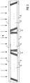
- FIG. 1 shows a scintillator 1 which is optically coupled to image converters 3 with the aid of fiber optics 2.
- the drawing shows that a plurality of image converters 3 adjoin one another in one area. They have optically inactive edge zones 4.
- the fiber optics 2 are under one so that no image dropouts are caused thereby from 90 ° different angles to the image converter 3 and the scintillator 1 inclined. They adjoin each other on the scintillator 1, thus capture the entire image of the scintillator 1, but leave the edge zones 4 of the image converter 3 free.
- the fiber optics 2 consist of bundles of parallel fibers which are cut off at the end at an angle deviating from 90 ° to the fiber axis. They are placed between the> image converter 3 and the scintillator 1 in such a way that they adjoin one another on the scintillator 1, but leave the edge zones 4 free.
- Arrows 6 also show the X-ray radiation that strikes the scintillator 1.
- the fiber optics 2 also serve to shield the image converter 3 against the X-rays.
- the image converter 3 covers a relatively large image field, so that relatively large objects can also be recorded. They can be in a row, but also as a matrix of e.g. four image converters can be arranged.
- Fig. 2 shows an embodiment in which the left fiber optic 2 in Fig. 1 is replaced by a fiber optic 5 which is perpendicular to the image converter 3, i.e. in contrast to the fiber optics 2 at an angle of 90 ° to the image converter 3.
- the edge zones 4 of the image converter 3 are also left free in this solution.
- FIG. 3 shows a solution in which three fiber optics 2, 5, 2 follow one another, corresponding to the sequence of three image converters 3.
- An X-ray image sensor of the type described is particularly suitable for mammography.
Landscapes
- Measurement Of Radiation (AREA)
- Transforming Light Signals Into Electric Signals (AREA)
- Conversion Of X-Rays Into Visible Images (AREA)
- Optical Fibers, Optical Fiber Cores, And Optical Fiber Bundles (AREA)
- Nuclear Medicine (AREA)
Applications Claiming Priority (4)
| Application Number | Priority Date | Filing Date | Title |
|---|---|---|---|
| DE4439260 | 1994-11-03 | ||
| DE4439260 | 1994-11-03 | ||
| DE19503034A DE19503034A1 (de) | 1994-11-03 | 1995-01-31 | Röntgenbildsensor |
| DE19503034 | 1995-01-31 |
Publications (2)
| Publication Number | Publication Date |
|---|---|
| EP0710985A1 true EP0710985A1 (fr) | 1996-05-08 |
| EP0710985B1 EP0710985B1 (fr) | 1998-03-25 |
Family
ID=25941653
Family Applications (1)
| Application Number | Title | Priority Date | Filing Date |
|---|---|---|---|
| EP95116643A Expired - Lifetime EP0710985B1 (fr) | 1994-11-03 | 1995-10-23 | Capteur de rayons X |
Country Status (3)
| Country | Link |
|---|---|
| US (1) | US5563414A (fr) |
| EP (1) | EP0710985B1 (fr) |
| JP (1) | JPH08211155A (fr) |
Families Citing this family (13)
| Publication number | Priority date | Publication date | Assignee | Title |
|---|---|---|---|---|
| US5715292A (en) * | 1994-11-25 | 1998-02-03 | Loral Fairchild Corporation | Digital sensor cassette for mammography |
| US6005911A (en) * | 1995-11-17 | 1999-12-21 | Trex Medical Corporation | Large area array, single exposure digital mammography |
| JP3582825B2 (ja) | 1998-12-14 | 2004-10-27 | 浜松ホトニクス株式会社 | 光学素子及びこれを用いた放射線検出器 |
| JP3276614B2 (ja) * | 1999-04-22 | 2002-04-22 | 浜松ホトニクス株式会社 | 光学素子、放射線イメージセンサ及び光学素子の製造方法 |
| JP3595759B2 (ja) | 1999-07-02 | 2004-12-02 | キヤノン株式会社 | 撮像装置および撮像システム |
| US6800857B2 (en) | 2000-08-10 | 2004-10-05 | Canon Kabushiki Kaisha | Large-area fiber plate, radiation image pickup apparatus utilizing the same and producing method therefor |
| US6800870B2 (en) * | 2000-12-20 | 2004-10-05 | Michel Sayag | Light stimulating and collecting methods and apparatus for storage-phosphor image plates |
| SE0100382D0 (sv) * | 2001-02-07 | 2001-02-07 | Lp Roentgenteknik Ab | X-ray detector |
| JP3870156B2 (ja) * | 2002-02-07 | 2007-01-17 | キヤノン株式会社 | ファイバープレートとその製造方法、放射線撮像装置、及び放射線撮像システム |
| IL158345A0 (en) * | 2003-10-09 | 2004-05-12 | Interon As | Pixel detector and method of manufacture and assembly thereof |
| JP7046698B2 (ja) | 2018-04-24 | 2022-04-04 | 浜松ホトニクス株式会社 | 放射線検出器、放射線検出器の製造方法、及び画像処理方法 |
| JP7206431B2 (ja) * | 2018-04-24 | 2023-01-17 | 浜松ホトニクス株式会社 | 放射線検出器、放射線検出器の製造方法、及び画像処理方法 |
| CN109545810A (zh) * | 2018-11-20 | 2019-03-29 | 京东方科技集团股份有限公司 | 一种平板探测器及其制备方法 |
Citations (4)
| Publication number | Priority date | Publication date | Assignee | Title |
|---|---|---|---|---|
| EP0296737A1 (fr) * | 1987-06-15 | 1988-12-28 | Seiko Instruments Inc. | Détecteur des rayons X |
| WO1991015785A1 (fr) * | 1990-04-11 | 1991-10-17 | Washington University | Procede et appareil de formage de multifibre en plastique |
| US5138642A (en) * | 1989-03-02 | 1992-08-11 | Innovative Imaging Systems, Inc. | Detector imaging arrangement for an industrial CT device |
| EP0597725A1 (fr) * | 1992-11-13 | 1994-05-18 | Debex (Proprietary) Limited | Système de balayage de corps |
Family Cites Families (6)
| Publication number | Priority date | Publication date | Assignee | Title |
|---|---|---|---|---|
| US4179100A (en) * | 1977-08-01 | 1979-12-18 | University Of Pittsburgh | Radiography apparatus |
| JPS58210582A (ja) * | 1982-05-31 | 1983-12-07 | Shimadzu Corp | 放射線位置検出器 |
| US4755681A (en) * | 1986-09-30 | 1988-07-05 | Shimadzu Corporation | Radiation image detecting apparatus with IC modules stacked stepwise |
| JPH0344966A (ja) * | 1989-07-13 | 1991-02-26 | Sony Corp | 固体撮像装置 |
| JP2507282Y2 (ja) * | 1990-11-26 | 1996-08-14 | 株式会社モリタ製作所 | 医療用x線画像検出装置 |
| US5391879A (en) * | 1993-11-19 | 1995-02-21 | Minnesota Mining And Manufacturing Company | Radiation detector |
-
1995
- 1995-10-13 US US08/542,910 patent/US5563414A/en not_active Expired - Lifetime
- 1995-10-23 EP EP95116643A patent/EP0710985B1/fr not_active Expired - Lifetime
- 1995-10-31 JP JP7283284A patent/JPH08211155A/ja active Pending
Patent Citations (4)
| Publication number | Priority date | Publication date | Assignee | Title |
|---|---|---|---|---|
| EP0296737A1 (fr) * | 1987-06-15 | 1988-12-28 | Seiko Instruments Inc. | Détecteur des rayons X |
| US5138642A (en) * | 1989-03-02 | 1992-08-11 | Innovative Imaging Systems, Inc. | Detector imaging arrangement for an industrial CT device |
| WO1991015785A1 (fr) * | 1990-04-11 | 1991-10-17 | Washington University | Procede et appareil de formage de multifibre en plastique |
| EP0597725A1 (fr) * | 1992-11-13 | 1994-05-18 | Debex (Proprietary) Limited | Système de balayage de corps |
Also Published As
| Publication number | Publication date |
|---|---|
| EP0710985B1 (fr) | 1998-03-25 |
| US5563414A (en) | 1996-10-08 |
| JPH08211155A (ja) | 1996-08-20 |
Similar Documents
| Publication | Publication Date | Title |
|---|---|---|
| EP0710985B1 (fr) | Capteur de rayons X | |
| DE3686163T2 (de) | Vorrichtung zur strahlungsbilderkennung. | |
| DE10160723A1 (de) | CT-Detektormodul mit verbesserter Szintillator/Dioden-Kopplung | |
| DE3118458C2 (de) | Lichtaufnahme-Vorrichtung | |
| DE19525605B4 (de) | Röntgen-Detektoranordnung mit verringertem effektivem Abstand | |
| DE19753268A1 (de) | Kollimator und Erfassungseinrichtung für Computer-Tomographie-Systeme | |
| DE3609669C2 (fr) | ||
| DE10358867A1 (de) | Tragestruktur für Z-verlängerbare CT Detektoren und Verfahren zu ihrer Herstellung | |
| EP0862748B1 (fr) | Agencement optique et procede pour la detection electronique d'une image radiographique | |
| EP0064736A1 (fr) | Dispositif récepteur de lumière | |
| EP1580765B1 (fr) | Collimateur secondaire pour dispositif à rayons X diffusés et dispositif à rayons X diffusés | |
| DE102005006573A1 (de) | Verfahren und Vorrichtung zum Verbessern einer Datenakquisition mittels eines Haltleiter-Digitalröntgendetektors | |
| DE69529656T2 (de) | Lichtkollektor mit optisch beschichtetem Acrylsubstrat | |
| DE102008063323A1 (de) | Strahlungsdetektor, Lichtdetektoranordnung, Herstellungsverfahren und bildgebendes System | |
| EP2240801B1 (fr) | Dispositif et procédé d'acquisition d'une image | |
| DE102008061486A1 (de) | Detektormodul für Röntgen- oder Gammastrahlung mit speziell ausgebildeten Streustrahlenraster | |
| DE112006000155T5 (de) | Sensor mit schmalem Montageprofil | |
| DE112018005374T5 (de) | Bildbelichtungsvorrichtung | |
| DE19503034A1 (de) | Röntgenbildsensor | |
| DE60210300T2 (de) | Fingerabdruck-Detektor | |
| DE3616530A1 (de) | Anordnung optischer elemente | |
| WO2003079372A1 (fr) | Detecteur destine a un tomodensitometre a rayons x | |
| DE2729291C2 (de) | Photoelektrischer Bildwandler | |
| EP3217408A2 (fr) | Module de focalisation pour un filtre de forme et filtre de forme destiné à régler une distribution de l'intensité spatiale d'un rayon x | |
| EP0819965A1 (fr) | Méthode et appareil pour enregistrer une information d'images |
Legal Events
| Date | Code | Title | Description |
|---|---|---|---|
| PUAI | Public reference made under article 153(3) epc to a published international application that has entered the european phase |
Free format text: ORIGINAL CODE: 0009012 |
|
| AK | Designated contracting states |
Kind code of ref document: A1 Designated state(s): DE FR GB IT |
|
| 17P | Request for examination filed |
Effective date: 19960604 |
|
| 17Q | First examination report despatched |
Effective date: 19970515 |
|
| GRAG | Despatch of communication of intention to grant |
Free format text: ORIGINAL CODE: EPIDOS AGRA |
|
| GRAG | Despatch of communication of intention to grant |
Free format text: ORIGINAL CODE: EPIDOS AGRA |
|
| GRAH | Despatch of communication of intention to grant a patent |
Free format text: ORIGINAL CODE: EPIDOS IGRA |
|
| GRAH | Despatch of communication of intention to grant a patent |
Free format text: ORIGINAL CODE: EPIDOS IGRA |
|
| GRAA | (expected) grant |
Free format text: ORIGINAL CODE: 0009210 |
|
| AK | Designated contracting states |
Kind code of ref document: B1 Designated state(s): DE FR GB IT |
|
| REF | Corresponds to: |
Ref document number: 59501697 Country of ref document: DE Date of ref document: 19980430 |
|
| ET | Fr: translation filed | ||
| GBT | Gb: translation of ep patent filed (gb section 77(6)(a)/1977) |
Effective date: 19980507 |
|
| ITF | It: translation for a ep patent filed | ||
| PGFP | Annual fee paid to national office [announced via postgrant information from national office to epo] |
Ref country code: FR Payment date: 19981023 Year of fee payment: 4 |
|
| PLBE | No opposition filed within time limit |
Free format text: ORIGINAL CODE: 0009261 |
|
| STAA | Information on the status of an ep patent application or granted ep patent |
Free format text: STATUS: NO OPPOSITION FILED WITHIN TIME LIMIT |
|
| 26N | No opposition filed | ||
| PG25 | Lapsed in a contracting state [announced via postgrant information from national office to epo] |
Ref country code: GB Free format text: LAPSE BECAUSE OF NON-PAYMENT OF DUE FEES Effective date: 19991023 |
|
| GBPC | Gb: european patent ceased through non-payment of renewal fee |
Effective date: 19991023 |
|
| PG25 | Lapsed in a contracting state [announced via postgrant information from national office to epo] |
Ref country code: FR Free format text: LAPSE BECAUSE OF NON-PAYMENT OF DUE FEES Effective date: 20000630 |
|
| REG | Reference to a national code |
Ref country code: FR Ref legal event code: ST |
|
| PGFP | Annual fee paid to national office [announced via postgrant information from national office to epo] |
Ref country code: DE Payment date: 20041220 Year of fee payment: 10 |
|
| PG25 | Lapsed in a contracting state [announced via postgrant information from national office to epo] |
Ref country code: IT Free format text: LAPSE BECAUSE OF NON-PAYMENT OF DUE FEES;WARNING: LAPSES OF ITALIAN PATENTS WITH EFFECTIVE DATE BEFORE 2007 MAY HAVE OCCURRED AT ANY TIME BEFORE 2007. THE CORRECT EFFECTIVE DATE MAY BE DIFFERENT FROM THE ONE RECORDED. Effective date: 20051023 |
|
| PG25 | Lapsed in a contracting state [announced via postgrant information from national office to epo] |
Ref country code: DE Free format text: LAPSE BECAUSE OF NON-PAYMENT OF DUE FEES Effective date: 20060503 |