EP0711208B1 - Auftragseinheit für leim - Google Patents
Auftragseinheit für leim Download PDFInfo
- Publication number
- EP0711208B1 EP0711208B1 EP94921582A EP94921582A EP0711208B1 EP 0711208 B1 EP0711208 B1 EP 0711208B1 EP 94921582 A EP94921582 A EP 94921582A EP 94921582 A EP94921582 A EP 94921582A EP 0711208 B1 EP0711208 B1 EP 0711208B1
- Authority
- EP
- European Patent Office
- Prior art keywords
- unit according
- applicator unit
- glue
- valve member
- valve
- Prior art date
- Legal status (The legal status is an assumption and is not a legal conclusion. Google has not performed a legal analysis and makes no representation as to the accuracy of the status listed.)
- Expired - Lifetime
Links
- 239000003292 glue Substances 0.000 title claims abstract description 80
- 238000009413 insulation Methods 0.000 claims description 28
- 239000000919 ceramic Substances 0.000 claims description 8
- 239000000463 material Substances 0.000 claims description 7
- 238000010438 heat treatment Methods 0.000 claims description 5
- 238000006073 displacement reaction Methods 0.000 claims description 4
- 239000000758 substrate Substances 0.000 abstract description 4
- 239000004831 Hot glue Substances 0.000 abstract description 3
- 239000012530 fluid Substances 0.000 abstract description 3
- 230000005540 biological transmission Effects 0.000 abstract description 2
- 238000004026 adhesive bonding Methods 0.000 description 6
- 125000006850 spacer group Chemical group 0.000 description 5
- 239000000853 adhesive Substances 0.000 description 3
- 230000001070 adhesive effect Effects 0.000 description 3
- 238000009826 distribution Methods 0.000 description 3
- 238000004519 manufacturing process Methods 0.000 description 3
- 238000000034 method Methods 0.000 description 3
- 238000004806 packaging method and process Methods 0.000 description 3
- 239000011111 cardboard Substances 0.000 description 2
- 238000010276 construction Methods 0.000 description 2
- 239000007789 gas Substances 0.000 description 2
- 239000007788 liquid Substances 0.000 description 2
- 229910052751 metal Inorganic materials 0.000 description 2
- 239000002184 metal Substances 0.000 description 2
- 230000002093 peripheral effect Effects 0.000 description 2
- 230000001133 acceleration Effects 0.000 description 1
- 229910052782 aluminium Inorganic materials 0.000 description 1
- XAGFODPZIPBFFR-UHFFFAOYSA-N aluminium Chemical compound [Al] XAGFODPZIPBFFR-UHFFFAOYSA-N 0.000 description 1
- 238000005452 bending Methods 0.000 description 1
- 230000015572 biosynthetic process Effects 0.000 description 1
- 238000002485 combustion reaction Methods 0.000 description 1
- 230000008602 contraction Effects 0.000 description 1
- 238000013016 damping Methods 0.000 description 1
- 230000001419 dependent effect Effects 0.000 description 1
- 230000000694 effects Effects 0.000 description 1
- 230000005672 electromagnetic field Effects 0.000 description 1
- 239000002657 fibrous material Substances 0.000 description 1
- 238000005755 formation reaction Methods 0.000 description 1
- 239000012943 hotmelt Substances 0.000 description 1
- 238000002347 injection Methods 0.000 description 1
- 239000007924 injection Substances 0.000 description 1
- 239000000314 lubricant Substances 0.000 description 1
- 230000005226 mechanical processes and functions Effects 0.000 description 1
- 238000002844 melting Methods 0.000 description 1
- 230000008018 melting Effects 0.000 description 1
- 239000003973 paint Substances 0.000 description 1
- 239000000123 paper Substances 0.000 description 1
- 230000036316 preload Effects 0.000 description 1
- 238000000926 separation method Methods 0.000 description 1
- 239000007779 soft material Substances 0.000 description 1
- 239000004753 textile Substances 0.000 description 1
Images
Classifications
-
- F—MECHANICAL ENGINEERING; LIGHTING; HEATING; WEAPONS; BLASTING
- F16—ENGINEERING ELEMENTS AND UNITS; GENERAL MEASURES FOR PRODUCING AND MAINTAINING EFFECTIVE FUNCTIONING OF MACHINES OR INSTALLATIONS; THERMAL INSULATION IN GENERAL
- F16K—VALVES; TAPS; COCKS; ACTUATING-FLOATS; DEVICES FOR VENTING OR AERATING
- F16K31/00—Actuating devices; Operating means; Releasing devices
- F16K31/004—Actuating devices; Operating means; Releasing devices actuated by piezoelectric means
- F16K31/007—Piezoelectric stacks
-
- B—PERFORMING OPERATIONS; TRANSPORTING
- B05—SPRAYING OR ATOMISING IN GENERAL; APPLYING FLUENT MATERIALS TO SURFACES, IN GENERAL
- B05C—APPARATUS FOR APPLYING FLUENT MATERIALS TO SURFACES, IN GENERAL
- B05C5/00—Apparatus in which liquid or other fluent material is projected, poured or allowed to flow on to the surface of the work
- B05C5/02—Apparatus in which liquid or other fluent material is projected, poured or allowed to flow on to the surface of the work the liquid or other fluent material being discharged through an outlet orifice by pressure, e.g. from an outlet device in contact or almost in contact, with the work
- B05C5/0225—Apparatus in which liquid or other fluent material is projected, poured or allowed to flow on to the surface of the work the liquid or other fluent material being discharged through an outlet orifice by pressure, e.g. from an outlet device in contact or almost in contact, with the work characterised by flow controlling means, e.g. valves, located proximate the outlet
Definitions
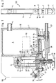
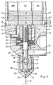
- a pressure plate 41' a heat insulation plate 42 'and an abutment plate 43' arranged separated from the corresponding plates 41 '', 42 '', 43 '' in the 1 vertical stroke direction are movable.
- the on the underside of the contact plate 43 'formed work surface 18 thus performs when applying a voltage to that Sub-element 2O 'a working stroke that is only created by the Voltage, but not dependent on the ambient temperature is. Only the stress-related elongation of the sub-element 2O 'occurs on the work surface 18 of the piezoelectric Elements 2O in appearance.
- a plate spring assembly 25 arranged, which the valve member 3O upwards against the working surface 18 of the piezoelectric element 2O presses.
- the plate spring assembly 25 extended with valve member 3O raised, to the right of the axis 11 compressed when the valve member is lowered shown.
Landscapes
- Engineering & Computer Science (AREA)
- General Engineering & Computer Science (AREA)
- Mechanical Engineering (AREA)
- Coating Apparatus (AREA)
- Seal Device For Vehicle (AREA)
- Adhesives Or Adhesive Processes (AREA)
- Pens And Brushes (AREA)
- Auxiliary Devices For And Details Of Packaging Control (AREA)
Description
Claims (28)
- Auftragseinheit zum Auftragen von unter Druck stehendem Leim oder dergleichen auf ein Beleimungsgut,mit einem Gehäuse (1O),mit einer in dem Gehäuse (1O) vorgesehenen, eine Achse (11) aufweisenden Ventilkammer (17), in der ein in der Achse (11) gelegener Ventilsitz (28) ausgebildet ist,mit einem in der Ventilkammer (17) in Richtung der Achse (11) beweglichen Ventilglied (3O), welches mit dem Ventilsitz (28) zur Bildung eines Leimaustrittsventils (4O) zusammenwirkt,mit einer auf der Austrittsseite des Leimaustrittsventils (4O) angeordneten Austritsdüse (31) für den Leim,mit einer auf der Eintrittsseite des Leimaustrittsventils (4O) vorgesehenen Zuführung (26,19) für unter Druck stehenden Leimund mit einem elektrisch betätigten Antrieb, mittels dessen das Ventilglied (3O) in Richtung der Achse (11) bewegbar ist,
dadurch gekennzeichnet,daß der Antrieb ein piezoelektrisches, an einem Ende in dem Gehäuse (1O) hinterlagertes Element (2O) umfaßt, dessen anderes Ende mit dem Ventilglied (3O) bewegungsverbunden ist,daß das Gehäuse (1O) in einen Leimführungsteil (2) und einen das piezoelektrische Element (2O) aufnehmenden Antriebsteil (1) unterteilt istund daß die Teile (1,2) gegeneinander wärmeisoliert sind. - Auftragseinheit nach Anspruch 1, dadurch gekennzeichnet, daß die einander zugewandten Begrenzungsflächen (1',2') des Antriebsteils (1) und des Leimführungsteils (2) im wesentlichen eben sind und einen Abstand (A) voneinander belassen und daß in dem Abstandsraum eine im wesentlichen ebene Wärmeisolationszone (3) vorgesehen ist, durch welche hindurch ein direkter Angriff des piezoelektrischen Elements (20) an dem Ventilglied (30) möglich ist.
- Auftragseinheit nach Anspruch 2, dadurch gekennzeichnet, daß die Wärmeisolationszone (3) unmittelbar an den Begrenzungsflächen (1',2') angreifende keramische Abstandsstücke umfaßt, die nur einen kleinen Teil der Grundfläche der Wärmeisolationszone (3) einnehmen.
- Auftragseinheit nach Anspruch 3, dadurch gekennzeichnet, daß die Abstandsstücke als Ringscheiben (13) ausgebildet sind.
- Auftragseinheit nach Anspruch 4, dadurch gekennzeichnet, daß sich durch mindestens einige der Ringscheiben (13) Verbindungsschrauben (12) hindurcherstrecken, die den Antriebsteil (1) und den Leimführungsteil (2) miteinander verbinden.
- Auftragseinheit nach Anspruch 2 bis 5, dadurch gekennzeichnet, daß die Wärmeisolationszone (3) ein mindestens einen Teil ihres Grundrisses überdeckendes plattenförmiges Wärmeisolationselement (53) umfaßt.
- Auftragseinheit nach Anspruch 6, dadurch gekennzeichnet, daß das Wärmeisolationselement (53) eine geringere Dicke als (A) aufweist und auf mindestens einer Seite einen Luftabstand zu der benachbarten Begrenzungsfläche (1',2') beläßt.
- Auftragseinheit nach Anspruch 7, dadurch gekennzeichnet, daß die Ringscheiben (13) außen eine Höhenstufe (54) aufweisen und daß das plattenförmige Wärmeisolationselement (53) auf den Höhenstufen (54) aufliegt.
- Auftragseinheit nach einem der Ansprüche 6 bis 8, dadurch gekennzeichnet, daß das plattenförmige Wärmeisolationselement (53) auf mindestens einer Seite eine wärmereflektierende Schicht (55) trägt.
- Auftragseinheit nach einem der Ansprüche 1 bis 9, dadurch gekennzeichnet, daß das piezoelektrische Element (2O) bei einer Ausdehnung zum Öffnen des Leimaustrittsventils (4O) das Ventilglied (3O) von dem Ventilsitz (28) abhebt und daß Schließmittel vorgesehen sind, mittels deren bei unbetätigtem piezoelektrischen Element (2O) das Ventilglied (3O) in Anlage an dem Ventilsitz (28) haltbar ist.
- Auftragseinheit nach Anspruche 10, dadurch gekennzeichnet, daß das Ventilglied (3O) einen Umfangsvorsprung (29) aufweist und mit dem Umfangsvorsprung (29) durch die Schließmittel gegen einen das Ventilglied (3O) ringförmig umgebenden Ventilsitz (28) ziehbar ist.
- Auftragseinheit nach Anspruch 11, dadurch gekennzeichnet, daß das Ventilglied (3O) eine axial verlagerbare Spindel (21) umfaßt, die nahe dem Umfangsvorsprung (29) durch Führungsmittel (48) radial in der Ventilkammer (17') geführt ist.
- Auftragseinheit nach einem der Ansprüche 1 bis 12, dadurch gekennzeichnet, daß das piezoelektrische Element (2O) blockförmig ausgebildet und in einer mit der Ventilkammer (17) im Grundriß fluchtenden Kammer (7) des Gehäuses (1O) angeordnet ist und daß der Ausdehnungshub des piezoelektrischen Elements (2O) in Bewegungsrichtung des Ventilglieds (3O) verläuft.
- Auftragseinheit nach Anspruch 13, dadurch gekennzeichnet, daß die Endfläche (18) des piezoelektrischen Elements (2O) unmittelbar am Ende des Ventilglieds (3O) anliegt.
- Auftragseinheit nach Anspruch 13 oder 14, dadurch gekennzeichnet, daß die andere Endfläche des piezoelektrischen Elements (2O) über eine eine Druckkraft in Richtung auf das Ventilglied (3O) ausübende Federanordnung (9) in der Kammer (7) abgestützt ist.
- Auftragseinheit nach einem der Ansprüche 1 bis 15, dadurch gekennzeichnet, daß Mittel zur Temperaturkompensation des piezoelektrischen Elements (2O) vorgesehen sind.
- Auftragseinheit nach Anspruch 16, dadurch gekennzeichnet, daß das piezoelektrische Element (2O) aus mehreren nebeneinander angeordneten Teilelementen (2O',2O'') besteht, von denen nur eines (20') elektrische Spannung erhält, deren Ausdehnungsrichtung einander und zur Verlagerungsrichtung des Ventilgliedes (3O) parallel ist, und die an dem der Endfläche (18) abgelegenen Ende in Ausdehnungsrichtung miteinander verbunden sind, so daß die durch die Temperaturdehnung bedingten Verlagerungen des Endes eines Teilelements (2O',2O'') die eines anderen Teilelements (2O'',2O') gleich sind und das piezoelektrische Element (2O) nach außen nur die spannungsbedingte Ausdehnung des Teilelements (20') zeigt.
- Auftragseinheit nach Anspruch 17, dadurch gekennzeichnet, daß die Teilelemente (2O',2O'') sich über eine entsprechend geteilte wärmeisolierende Platte (42',42'') an dem Leimführungsteil bzw. an dem Ventilglied (3O) abstützen.
- Auftragseinheit nach einem der Ansprüche 1 bis 18, dadurch gekennzeichnet, daß eine Einrichtung (5O) zur Steuerung des zeitlichen Verlaufs der an das piezoelektrische Element (2O) während des Ausdehnungshubs angelegten Spannung vorgesehen ist.
- Auftragseinheit nach einem der Ansprüche 1 bis 19, dadurch gekennzeichnet, daß der Leimführungsteil (2) beheizt ist.
- Auftragseinheit nach Anspruch 2O, dadurch gekennzeichnet, daß die Beheizung durch eine Heizpatrone erfolgt und das plattenförmige Wärmeisolationselement (53) mindestens den Bereich der Heizpatrone überdeckt.
- Auftragseinheit nach einem der Ansprüche 1O bis 21, dadurch gekennzeichnet, daß die Schließmittel auf das Ventilglied (3O) eine ständige, in seiner Bewegungsrichtung wirkende elastische Kraft ausüben.
- Auftragseinheit nach Anspruch 22, dadurch gekennzeichnet, daß die Kraft eine Druckkraft ist.
- Auftragseinheit nach Anspruch 22 oder 23, dadurch gekennzeichnet, daß die Schließmittel eine Federanordnung umfassen.
- Auftragseinheit nach Anspruch 24, dadurch gekennzeichnet, daß die Federanordnung durch ein zwischen dem Boden (24) der Ventilkammer (17) und einem Umfangsvorsprung (23) des Ventilgliedes (3O) wirkendes Tellerfederpaket (25) gegeben ist.
- Auftragseinheit nach Anspruch 22 oder 23, dadurch gekennzeichnet, daß die Schließmittel einen elastomeren Körper umfassen.
- Auftragseinheit nach Anspruch 22 oder 23, dadurch gekennzeichnet, daß die Schließmittel ein Gasvolumen umfassen.
- Auftragseinheit nach einem der Ansprüche 1 bis 27, dadurch gekennzeichnet, daß die Auftragseinheit (1OO) eine plattenförmige Gestalt mit einer Dicke (4) von 1O bis 2O mm aufweist, die Austrittsdüse (31) am Rand der Platte gelegen ist und die Austrittsrichtung parallel zur Plattenebene verläuft.
Applications Claiming Priority (3)
| Application Number | Priority Date | Filing Date | Title |
|---|---|---|---|
| DE4325143 | 1993-07-27 | ||
| DE4325143A DE4325143C1 (de) | 1993-07-27 | 1993-07-27 | Auftragseinheit für Leim |
| PCT/DE1994/000847 WO1995003894A1 (de) | 1993-07-27 | 1994-07-22 | Auftragseinheit für leim |
Publications (2)
| Publication Number | Publication Date |
|---|---|
| EP0711208A1 EP0711208A1 (de) | 1996-05-15 |
| EP0711208B1 true EP0711208B1 (de) | 1998-03-25 |
Family
ID=6493806
Family Applications (1)
| Application Number | Title | Priority Date | Filing Date |
|---|---|---|---|
| EP94921582A Expired - Lifetime EP0711208B1 (de) | 1993-07-27 | 1994-07-22 | Auftragseinheit für leim |
Country Status (5)
| Country | Link |
|---|---|
| EP (1) | EP0711208B1 (de) |
| AT (1) | ATE164330T1 (de) |
| AU (1) | AU7225994A (de) |
| DE (2) | DE4325143C1 (de) |
| WO (1) | WO1995003894A1 (de) |
Families Citing this family (17)
| Publication number | Priority date | Publication date | Assignee | Title |
|---|---|---|---|---|
| US5292068A (en) * | 1992-08-17 | 1994-03-08 | Nordson Corporation | One-piece, zero cavity nozzle for swirl spray of adhesive |
| DE4411569C1 (de) * | 1994-04-02 | 1995-07-20 | Itw Dynatec Gmbh Klebetechnik | Auftragskopf zur dosierten Abgabe von strömenden Medien |
| DE29713744U1 (de) * | 1997-08-01 | 1998-12-03 | Planatol Klebetechnik GmbH, 83101 Rohrdorf | Leim- und/oder Befeuchtungseinrichtung |
| DE19752150A1 (de) * | 1997-11-25 | 1999-05-27 | Focke & Co | Ventil, insbesondere Leimventil |
| DE19802723A1 (de) * | 1998-01-24 | 1999-08-12 | Kuesters Beloit Gmbh & Co Kg | Walze |
| US6157115A (en) * | 1998-10-13 | 2000-12-05 | Nordson Corporation | Mechanical amplifier |
| DE20314591U1 (de) * | 2003-09-20 | 2003-11-20 | Achenbach Buschhütten GmbH, 57223 Kreuztal | Walzenkühl- und/oder Schmiervorrichtung für Walzwerke, insbesondere Feinband- und Folienwalzwerke |
| EP1731306A1 (de) * | 2005-06-06 | 2006-12-13 | Krögel Gmbh & Co. KG | Düsenauftragsverfahren zum Beschichten und Kaschieren von Warenbahnen |
| CN103111402B (zh) * | 2013-03-08 | 2015-05-27 | 厦门大学 | 一种喷射点胶头 |
| DE102013102693A1 (de) | 2013-03-15 | 2014-09-18 | Vermes Microdispensing GmbH | Dosierventil und Dosierverfahren |
| CN104148250B (zh) * | 2014-07-11 | 2016-08-24 | 常熟市振宇胶带有限公司 | 热熔胶布基胶带涂布机构 |
| US10022744B2 (en) | 2015-05-22 | 2018-07-17 | Nordson Corporation | Piezoelectric jetting system with quick release jetting valve |
| CN107635675B (zh) | 2015-05-22 | 2023-06-13 | 诺信公司 | 具有放大机构的压电喷射系统和方法 |
| CN107303753B (zh) * | 2016-04-22 | 2020-11-24 | 北京派和智能装备技术有限公司 | 压电喷射打印头和具有该打印头的打印装置 |
| CN111282775B (zh) * | 2020-05-12 | 2020-08-04 | 江苏高凯精密流体技术股份有限公司 | 一种压电喷射阀的流量控制装置及其控制方法 |
| CN111632797B (zh) * | 2020-06-10 | 2021-05-07 | 东莞市集韵自动化科技有限公司 | 一种喷嘴可调式自适应压电喷射阀 |
| CN114714745B (zh) * | 2022-05-10 | 2023-12-29 | 泉州市依曼纺服饰制造有限公司 | 一种无纺布布料复合成型装置 |
Family Cites Families (7)
| Publication number | Priority date | Publication date | Assignee | Title |
|---|---|---|---|---|
| US1504773A (en) * | 1922-03-31 | 1924-08-12 | Marston Sheldon | Electromagnetic valve |
| DE3200469C2 (de) * | 1982-01-09 | 1985-01-03 | Dittberner GmbH, 4006 Erkrath | Einrichtung zum längenabschnittweisen Auftragen von Leim auf eine laufende Bahn |
| DE3637631C1 (de) * | 1986-11-05 | 1987-08-20 | Philips Patentverwaltung | Verfahren zum Aufbringen kleiner schmelzfluessiger,tropfenfoermiger Lotmengen aus einer Duese auf zu benetzende Flaechen und Vorrichtung zur Durchfuehrung des Verfahrens |
| SE8704685D0 (sv) * | 1987-11-25 | 1987-11-25 | Mytronic Ab | Anordning for att med tvangsstyrd slangvolym snabbt legga ut pastor och lim |
| SE461822B (sv) * | 1988-07-08 | 1990-03-26 | Mydata Automation Ab | Anordning foer att laegga ut pastor och lim i diskreta punkter, foeretraedesvis vid ytmontering av komponenter paa kretskort |
| DE3841474A1 (de) * | 1988-12-09 | 1990-06-13 | Macon Gmbh Klebstoff Auftragsg | Ventil zur zeitgesteuerten abgabe von fluessigem bis gelartigem medium |
| SE465756B (sv) * | 1990-03-02 | 1991-10-28 | Qenico Ab | Anordning foer flaeckvis applicering av loedpasta, lim, e d, paa ett substrat |
-
1993
- 1993-07-27 DE DE4325143A patent/DE4325143C1/de not_active Expired - Fee Related
-
1994
- 1994-07-22 DE DE59405537T patent/DE59405537D1/de not_active Expired - Lifetime
- 1994-07-22 WO PCT/DE1994/000847 patent/WO1995003894A1/de not_active Ceased
- 1994-07-22 EP EP94921582A patent/EP0711208B1/de not_active Expired - Lifetime
- 1994-07-22 AT AT94921582T patent/ATE164330T1/de not_active IP Right Cessation
- 1994-07-22 AU AU72259/94A patent/AU7225994A/en not_active Abandoned
Also Published As
| Publication number | Publication date |
|---|---|
| AU7225994A (en) | 1995-02-28 |
| DE59405537D1 (de) | 1998-04-30 |
| ATE164330T1 (de) | 1998-04-15 |
| DE4325143C1 (de) | 1994-12-22 |
| WO1995003894A1 (de) | 1995-02-09 |
| EP0711208A1 (de) | 1996-05-15 |
Similar Documents
| Publication | Publication Date | Title |
|---|---|---|
| EP0711208B1 (de) | Auftragseinheit für leim | |
| EP0366605B1 (de) | Elektrohydraulische oder -pneumatische Stellvorrichtung | |
| EP2528695B1 (de) | Auftragskopf zum abgeben eines fliessfähigen mediums und auftragsvorrichtung zum abgeben eines fliessfähigen mediums | |
| EP2400193B1 (de) | Vorrichtung zur Durchflussregelung eines flüssigen oder gasförmigen Mediums | |
| EP1454053B1 (de) | Brennstoffeinspritzventil | |
| DE2917933A1 (de) | Regelventil | |
| EP0770776A1 (de) | Servoventil für eine Einspritzdüse | |
| DE2931874A1 (de) | Elektrisch betaetigbares ventil | |
| DE19947848A1 (de) | Aktuator zur Betätigung eines Stellgliedes, insbesondere eines Gaswechselventils mit einseitiger Federanordnung | |
| EP1658902B1 (de) | Steuermodul für eine Düsenanordnung | |
| EP0676247B1 (de) | Auftragskopf zur dosierten Abgabe von strömenden Medien | |
| EP0795081B1 (de) | Elektrohydraulischer antrieb | |
| DE9405600U1 (de) | Auftragskopf zur dosierten Abgabe von strömenden Medien | |
| EP2167856B1 (de) | Piezoelektrisches ventil | |
| EP3902022A1 (de) | Piezoaktuator und piezoaktuator-array | |
| EP3687701B1 (de) | Applikator mit einem geringen düsenabstand | |
| EP2081748A1 (de) | Spritzgiessvorrichtung mit nadelverschlussdüsen in rücken-an-rücken-anordnung | |
| DE2918377A1 (de) | Ventil fuer stroemende medien | |
| DE4412948A1 (de) | Elektrohydraulische Absperrvorrichtung | |
| WO2020001825A1 (de) | Schiebeverschluss für ein metallurgisches gefäss, vorzugsweise ein verteilergefäss für eine stranggiessanlage | |
| DE69716003T2 (de) | Verfahren und Vorrichtung zum Bilden und Bewegen von Tintentröpfen | |
| DE4018094C2 (de) | ||
| EP1144847A1 (de) | Brennstoffeinspritzventil | |
| WO2022028965A1 (de) | Ventil für fliessfähige medien | |
| EP1681101B1 (de) | Vorrichtung zur intermittierenden Abgabe von fluiden Medien |
Legal Events
| Date | Code | Title | Description |
|---|---|---|---|
| PUAI | Public reference made under article 153(3) epc to a published international application that has entered the european phase |
Free format text: ORIGINAL CODE: 0009012 |
|
| 17P | Request for examination filed |
Effective date: 19960102 |
|
| AK | Designated contracting states |
Kind code of ref document: A1 Designated state(s): AT BE CH DE ES FR GB IT LI NL SE |
|
| 17Q | First examination report despatched |
Effective date: 19970516 |
|
| GRAG | Despatch of communication of intention to grant |
Free format text: ORIGINAL CODE: EPIDOS AGRA |
|
| GRAG | Despatch of communication of intention to grant |
Free format text: ORIGINAL CODE: EPIDOS AGRA |
|
| GRAH | Despatch of communication of intention to grant a patent |
Free format text: ORIGINAL CODE: EPIDOS IGRA |
|
| GRAH | Despatch of communication of intention to grant a patent |
Free format text: ORIGINAL CODE: EPIDOS IGRA |
|
| RAP1 | Party data changed (applicant data changed or rights of an application transferred) |
Owner name: ITW INDUSTRIE GMBH |
|
| GRAA | (expected) grant |
Free format text: ORIGINAL CODE: 0009210 |
|
| AK | Designated contracting states |
Kind code of ref document: B1 Designated state(s): AT BE CH DE ES FR GB IT LI NL SE |
|
| PG25 | Lapsed in a contracting state [announced via postgrant information from national office to epo] |
Ref country code: NL Free format text: LAPSE BECAUSE OF FAILURE TO SUBMIT A TRANSLATION OF THE DESCRIPTION OR TO PAY THE FEE WITHIN THE PRESCRIBED TIME-LIMIT Effective date: 19980325 Ref country code: ES Free format text: THE PATENT HAS BEEN ANNULLED BY A DECISION OF A NATIONAL AUTHORITY Effective date: 19980325 |
|
| REF | Corresponds to: |
Ref document number: 164330 Country of ref document: AT Date of ref document: 19980415 Kind code of ref document: T |
|
| REG | Reference to a national code |
Ref country code: CH Ref legal event code: EP |
|
| GBT | Gb: translation of ep patent filed (gb section 77(6)(a)/1977) |
Effective date: 19980326 |
|
| REF | Corresponds to: |
Ref document number: 59405537 Country of ref document: DE Date of ref document: 19980430 |
|
| ET | Fr: translation filed | ||
| ITF | It: translation for a ep patent filed | ||
| PG25 | Lapsed in a contracting state [announced via postgrant information from national office to epo] |
Ref country code: AT Free format text: LAPSE BECAUSE OF NON-PAYMENT OF DUE FEES Effective date: 19980722 |
|
| PG25 | Lapsed in a contracting state [announced via postgrant information from national office to epo] |
Ref country code: LI Free format text: LAPSE BECAUSE OF NON-PAYMENT OF DUE FEES Effective date: 19980731 Ref country code: CH Free format text: LAPSE BECAUSE OF NON-PAYMENT OF DUE FEES Effective date: 19980731 Ref country code: BE Free format text: LAPSE BECAUSE OF NON-PAYMENT OF DUE FEES Effective date: 19980731 |
|
| NLV1 | Nl: lapsed or annulled due to failure to fulfill the requirements of art. 29p and 29m of the patents act | ||
| PLBE | No opposition filed within time limit |
Free format text: ORIGINAL CODE: 0009261 |
|
| STAA | Information on the status of an ep patent application or granted ep patent |
Free format text: STATUS: NO OPPOSITION FILED WITHIN TIME LIMIT |
|
| BERE | Be: lapsed |
Owner name: ITW INDUSTRIE G.M.B.H. Effective date: 19980731 |
|
| REG | Reference to a national code |
Ref country code: CH Ref legal event code: PL |
|
| 26N | No opposition filed | ||
| REG | Reference to a national code |
Ref country code: GB Ref legal event code: IF02 |
|
| PGFP | Annual fee paid to national office [announced via postgrant information from national office to epo] |
Ref country code: FR Payment date: 20020702 Year of fee payment: 9 |
|
| PG25 | Lapsed in a contracting state [announced via postgrant information from national office to epo] |
Ref country code: FR Free format text: LAPSE BECAUSE OF NON-PAYMENT OF DUE FEES Effective date: 20040331 |
|
| REG | Reference to a national code |
Ref country code: FR Ref legal event code: ST |
|
| PGFP | Annual fee paid to national office [announced via postgrant information from national office to epo] |
Ref country code: GB Payment date: 20040714 Year of fee payment: 11 |
|
| PGFP | Annual fee paid to national office [announced via postgrant information from national office to epo] |
Ref country code: SE Payment date: 20040721 Year of fee payment: 11 |
|
| PG25 | Lapsed in a contracting state [announced via postgrant information from national office to epo] |
Ref country code: IT Free format text: LAPSE BECAUSE OF NON-PAYMENT OF DUE FEES Effective date: 20050722 Ref country code: GB Free format text: LAPSE BECAUSE OF NON-PAYMENT OF DUE FEES Effective date: 20050722 |
|
| PG25 | Lapsed in a contracting state [announced via postgrant information from national office to epo] |
Ref country code: SE Free format text: LAPSE BECAUSE OF NON-PAYMENT OF DUE FEES Effective date: 20050723 |
|
| EUG | Se: european patent has lapsed | ||
| GBPC | Gb: european patent ceased through non-payment of renewal fee |
Effective date: 20050722 |
|
| PGFP | Annual fee paid to national office [announced via postgrant information from national office to epo] |
Ref country code: DE Payment date: 20130729 Year of fee payment: 20 |
|
| REG | Reference to a national code |
Ref country code: DE Ref legal event code: R071 Ref document number: 59405537 Country of ref document: DE |
|
| PG25 | Lapsed in a contracting state [announced via postgrant information from national office to epo] |
Ref country code: DE Free format text: LAPSE BECAUSE OF EXPIRATION OF PROTECTION Effective date: 20140723 |