EP0711570A1 - Procédé et dispositif pour le nettoyage intérieur d'un système de perfusion implanté - Google Patents
Procédé et dispositif pour le nettoyage intérieur d'un système de perfusion implanté Download PDFInfo
- Publication number
- EP0711570A1 EP0711570A1 EP94117947A EP94117947A EP0711570A1 EP 0711570 A1 EP0711570 A1 EP 0711570A1 EP 94117947 A EP94117947 A EP 94117947A EP 94117947 A EP94117947 A EP 94117947A EP 0711570 A1 EP0711570 A1 EP 0711570A1
- Authority
- EP
- European Patent Office
- Prior art keywords
- flow
- fluid
- piston
- flushing port
- cylinder
- Prior art date
- Legal status (The legal status is an assumption and is not a legal conclusion. Google has not performed a legal analysis and makes no representation as to the accuracy of the status listed.)
- Withdrawn
Links
Images


Classifications
-
- A—HUMAN NECESSITIES
- A61—MEDICAL OR VETERINARY SCIENCE; HYGIENE
- A61M—DEVICES FOR INTRODUCING MEDIA INTO, OR ONTO, THE BODY; DEVICES FOR TRANSDUCING BODY MEDIA OR FOR TAKING MEDIA FROM THE BODY; DEVICES FOR PRODUCING OR ENDING SLEEP OR STUPOR
- A61M5/00—Devices for bringing media into the body in a subcutaneous, intra-vascular or intramuscular way; Accessories therefor, e.g. filling or cleaning devices, arm-rests
- A61M5/14—Infusion devices, e.g. infusing by gravity; Blood infusion; Accessories therefor
- A61M5/142—Pressure infusion, e.g. using pumps
- A61M5/14244—Pressure infusion, e.g. using pumps adapted to be carried by the patient, e.g. portable on the body
- A61M5/14276—Pressure infusion, e.g. using pumps adapted to be carried by the patient, e.g. portable on the body specially adapted for implantation
-
- A—HUMAN NECESSITIES
- A61—MEDICAL OR VETERINARY SCIENCE; HYGIENE
- A61M—DEVICES FOR INTRODUCING MEDIA INTO, OR ONTO, THE BODY; DEVICES FOR TRANSDUCING BODY MEDIA OR FOR TAKING MEDIA FROM THE BODY; DEVICES FOR PRODUCING OR ENDING SLEEP OR STUPOR
- A61M25/00—Catheters; Hollow probes
- A61M2025/0019—Cleaning catheters or the like, e.g. for reuse of the device, for avoiding replacement
Definitions
- the present invention relates to a method and a device for internal cleaning of an implanted infusion system, comprising an infusion pump connected on its outlet side to a catheter via a nonreturn valve, a flushing port also being provided downstream the nonreturn valve and upstream the catheter, a first flow of cleaning fluid being passed through the infusion pump and the nonreturn valve.
- Implantable infusion systems or infusers deliver medication or drugs, usually in liquid form, such as an insulin solution, to the patient.
- an infuser can consist of a.o. a drug reservoir, a micropump with a nonreturn valve and a catheter.
- medication can become deposited on the interior surfaces of a.o. the pump and the nonreturn valve.
- a reduced volume delivered per pump stroke, valve leakage etc. are some of the disruptions which then can occur. If such a disruption occurs, the deposits in the system can be dissolved and the pump performances restored.
- the reservoir can be filled with some cleaning or washing liquid which dissolves the deposits in question and allow the liquid to pass through the pump by activating the pump funktion.
- washing liquid can be aggressive, toxic or unapproved as a drug etc., it is important to prevent the liquid from being pumped out of the catheter and coming into contact with body tissues. Allowing dissolved drug deposits to enter the body is further inappropriate, since this can cause immune reactions. For example, denatured insulin in the abdominal cavity can give rise to the formation of antibodies, and the patient can ultimately develop resistance to insulin. Therefore no flow of washing liquid out of the catheter is desirable during the washing operation. Nor is an influx of body fluid into the catheter desirable. Body fluids contain a.o. proteins which can contribute to catheter blockage and contamination of the so-called flushing port preceding the catheter. The presence of body fluid in this part of the infuser can have an adverse effect on the drug and on the life of the infuser.
- a drain consisting of a liquid-filled flexible tube
- the flushing port with its other end positioned on a level lower than the tip of the catheter.
- any free fluid in the abdominal cavity then flows back through the catheter out into the drain.
- Pumped washing liquid often pumped with intermittent pump strokes, will then be distributed between the catheter and the drain in a ratio determined by the transient flow resistances. In favorable conditions, the quantity of washing liquid exiting through the catheter will be returned to the drain because of the retrograde siphon flow of body fluid in the catheter.
- the method has several major weaknesses.
- the object of the present invention is to make washing of the interior of infusion systems with aggressive fluids possible without risk to the patient or to the infusion system, in already implanted infusion systems and in future systems equipped with a flushing port.
- the invention is applicable to infusion systems with a so-called flushing port downstream the pump valve but upstream from the catheter.
- a check can be performed with a cannula and syringe through this flushing port to ensure that the catheter is open an if this is not the case, an applied pressure/flow will often re-open the catheter and restore the function.
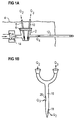
- the liquid mixture is extracted with a flow Q3, through another cannula 10, through the flushing septum 6, the flow Q3 being in a very exact ratio to Q1 and Q2. In this way, the desired magnitude of the resultant outflow Q4 of the liquid mixture through the catheter 12 can be controlled very exactly.
- Q1 + Q2 Q3 + Q4 and Q2, Q3 >> Q1
- the secondary liquid or fluid can be a) neutral, e.g. distilled water, just to physically dilute the washing liquid or fluid to a harmless concentration, or b) chemically active to neutralize the washing liquid or fluid for the purpose of making it harmless to body tissue.
- the washing liquid or fluid can be a NaOH solution
- the secondary liquid or fluid can in case a) be sterile water and in case b) a buffer solution which effectively reduces the pH value of the mixture, an acid solution etc.
- the two cannulas 8, 10 for secondary and transport fluids can advantageously be replaced with a double-lumen cannula 16 (FIG. 1B) to facilitate the whole procedure and reduce the trauma to both the patient and the flushing septum (a small area is unable to withstand many punctures, is difficult to locate in a stout patient etc.).
- a relatively large distance between the orifices 18, 20 for the flows Q2 and Q3 respectively is desired to avoid any flow occurring straight from the orifice 18 to the orifice 20.
- the device according to the invention makes it possible to retain, with great accuracy, a given ratio between the flows Q1, Q2 and Q3 with simple equipment.
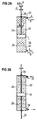
- FIG. 2A a first embodiment of the pump means in the device according to the invention in the form of a syringe with a cylinder 22 in which a piston 28 is displaceable.
- the piston 28 can be manipulated with a piston rod 30.
- Each end of the cylinder 30 is provided with openings 32, 34 for the intake and pumping out of fluid as the piston 28 is moved.
- FIG. 2B is shown an alternative version with a similar piston rod 36, 38 attached to either side of the piston 40.
- the flows Q out , Q in resulting when the piston 40 is moved are equal.
- FIG. 3 is shown another alternative version with two piston rods 42, 44, the two piston rods 42, 44 having different dimensions. If the diameter of the piston rod 42 is denoted by d B and the diameter of the piston rod 44 by d A , the following conditions will apply to the flows Q A and Q B resulting when the piston 46 is moved downwards in the FIG.
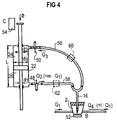
- FIG. 4 is shown the syringe in FIG. 2B connected by the flexible tubes 56, 58 and a double-lumen catheter 16 to the flushing port 2.
- a dilution factor m and the flow Q4 (cf. FIG. 4), the parameters d1, d2, d3 and the feed velocity v can be selected and calculated respectively.
- One dimensioning example is as follows:
- the syringe 24, 26 can be equipped with e.g. a three-way cock 48, 50 according to FIG.4 or some similar means through which the system can be de-aired.
- the infusion pump is delivering the flow Q1 which is comprised of first 0,4 ml buffer solution followed by 0,4 ml of 50 mM NaOH and finally 0,6 ml buffer solution, that is a total volume of liquid of 1,4 ml.
- This liquid is continuously mixed with the secondary fluid supplied into the flushing port by a syringe and sucked out again such that the flow out through the catheter is zero or approximately zero, that is Q2 ⁇ Q3 or Q A ⁇ Q B in figures 2 - 4.
- the secondary fluid can have a purely diluting effect, but is preferably buffering, which gives a better result. For several reasons it is desirable to rinse with the secondary fluid during the whole procedure and not only in the phase during which NaOH is supplied.
- the piston of the secondary fluid syringe is moved with an essentially constant velocity v1, first in forward direction with this velocity for a time t1, whereupon the piston is moved with the same velocity in the opposite direction for a time t2 which is shorter than the time t1. Thereafter the piston is moved in the forward direction for another period t1 followed by movement in the opposite direction during a time t2 and so on.
- the average velocity v ⁇ is given by and adapted such that the piston of the syringe will reach its end position at the same time or after the termination of the primary flow Q1.
- Another method of operating the device shown in e.g. figure 2B is to move the piston of the secondary fluid syringe from one end postion to the other and then back to the first end position and so on.
- the concentration of primary fluid will increase during the operation, since the secondary fluid is re-used for dilution of the primary fluid for a plurality of times.
- the concentration of NaOH at the end of the procedure will be ⁇ 0,4 ml 50 mM NaOH in 39 ml fluid volume in the secondary fluid syringe, that is the concentration will be ml caustic solution/ml fluid.
- This dilution fulfils by a very wide margin the requirement for a harmless pH value of the fluid reaching the abdominal cavity, provided that as secondary fluid is used e.g. the "dilution buffer" made by the company Hoechst.
- the flow Q2 can be measured outside the fluid pathway, e.g.
- a non-homogenous fluid to which e.g. very small particles are added, might possibly be needed for a doppler meter in order to give a signal diffused back with sufficient strength.
- the equipment can advantageously comprise sterilized disposable articles made of rubber and plastic, such as commercially available syringes. Piston operation can be accomplished with commercially available infusion equipment with appropriate performances.
- One major advantage with the equipment is that one and the same piston and piston rod provide both outflow and inflow.
- the momentary Q2/Q3 ratio is independent of fluctuations in the velocity v.
- a slow spatial variation in the diameter d3 along the length of the syringe 22 only affects the Q2/Q3 ratio slightly or not at all.
- FIGS. 5A and 5B show two possible versions which, however, do not exhibit said advantages.
- FIG. 5 is thus shown one version of pumping means with two parallel cylinders 64, 66, each with a piston 68, 70, said pistons 68, 70 being interconnected for joint movement.
- the cylinders 64, 66 are devised with openings 72, 74 and 76, 78 respectively at opposite ends, whereby a flow of fluid is pumped out through one of the openings, and a flow of fluid is drawn in through the other opening, or vice-versa depending on the direction of movement of the pistons 68, 70.
- the flow Q1 of cleaning fluid is very small (about 10 ⁇ 10 m3/s), whereas the flows Q2 and Q3 can be e.g. 100 times larger.
- Such an imbalance can occur in the devices in FIG. 5 if extraordinary measures are not taken, but not in the device in FIG. 4.
- Even if a relatively simple equipment is used with moderately low tolerance requirements and even if the piston is made of rubber, and is thus capable of deformation and possibly jerky movement, the piston is incompressible and does not change the Q2/Q3 ratio.
- the accuracy of the desired flow Q4 is just as good or better than the accuracy attainable with very expensive and complex equipment which would not be able to utilize sterilized disposable articles.
- the invention has been described above as applied to a system with the catheter opening into the abdominal cavity. However, the invention is obviously applicable to systems with the catheter opening into other sites in the body, e.g. into blood vessels.
- the above-mentioned secondary fluid or liquid can be a diluent fluid for purely physical dilution of the cleaning fluid.
- dilution is often inadequate in rendering the diluted fluid harmless to body tissue, and therefore the secondary fluid often consists of a buffer solution.
- an acid could also be used as secondary fluid.
Landscapes
- Health & Medical Sciences (AREA)
- Vascular Medicine (AREA)
- Engineering & Computer Science (AREA)
- Anesthesiology (AREA)
- Biomedical Technology (AREA)
- Heart & Thoracic Surgery (AREA)
- Hematology (AREA)
- Life Sciences & Earth Sciences (AREA)
- Animal Behavior & Ethology (AREA)
- General Health & Medical Sciences (AREA)
- Public Health (AREA)
- Veterinary Medicine (AREA)
- Infusion, Injection, And Reservoir Apparatuses (AREA)
Priority Applications (1)
| Application Number | Priority Date | Filing Date | Title |
|---|---|---|---|
| EP94117947A EP0711570A1 (fr) | 1994-11-14 | 1994-11-14 | Procédé et dispositif pour le nettoyage intérieur d'un système de perfusion implanté |
Applications Claiming Priority (1)
| Application Number | Priority Date | Filing Date | Title |
|---|---|---|---|
| EP94117947A EP0711570A1 (fr) | 1994-11-14 | 1994-11-14 | Procédé et dispositif pour le nettoyage intérieur d'un système de perfusion implanté |
Publications (1)
| Publication Number | Publication Date |
|---|---|
| EP0711570A1 true EP0711570A1 (fr) | 1996-05-15 |
Family
ID=8216458
Family Applications (1)
| Application Number | Title | Priority Date | Filing Date |
|---|---|---|---|
| EP94117947A Withdrawn EP0711570A1 (fr) | 1994-11-14 | 1994-11-14 | Procédé et dispositif pour le nettoyage intérieur d'un système de perfusion implanté |
Country Status (1)
| Country | Link |
|---|---|
| EP (1) | EP0711570A1 (fr) |
Cited By (4)
| Publication number | Priority date | Publication date | Assignee | Title |
|---|---|---|---|---|
| WO2005000386A1 (fr) * | 2003-06-02 | 2005-01-06 | Boston Scientific Limited | Dispositifs medicaux |
| WO2018145865A1 (fr) * | 2017-02-13 | 2018-08-16 | Cardiobridge Gmbh | Système de rinçage |
| US10357600B2 (en) | 2013-12-11 | 2019-07-23 | Gambro Lundia Ab | Extracorporeal blood treatment system, disposable set and valve unit for pre/post infusion |
| GB2586680A (en) * | 2019-08-28 | 2021-03-03 | Mokita Medical Gmbh | Flushing devices and methods |
Citations (1)
| Publication number | Priority date | Publication date | Assignee | Title |
|---|---|---|---|---|
| US4573994A (en) * | 1979-04-27 | 1986-03-04 | The Johns Hopkins University | Refillable medication infusion apparatus |
-
1994
- 1994-11-14 EP EP94117947A patent/EP0711570A1/fr not_active Withdrawn
Patent Citations (1)
| Publication number | Priority date | Publication date | Assignee | Title |
|---|---|---|---|---|
| US4573994A (en) * | 1979-04-27 | 1986-03-04 | The Johns Hopkins University | Refillable medication infusion apparatus |
Cited By (11)
| Publication number | Priority date | Publication date | Assignee | Title |
|---|---|---|---|---|
| WO2005000386A1 (fr) * | 2003-06-02 | 2005-01-06 | Boston Scientific Limited | Dispositifs medicaux |
| US7435237B2 (en) | 2003-06-02 | 2008-10-14 | Boston Scientific Scimed, Inc. | Mixing syringes with breakable septums |
| US10357600B2 (en) | 2013-12-11 | 2019-07-23 | Gambro Lundia Ab | Extracorporeal blood treatment system, disposable set and valve unit for pre/post infusion |
| WO2018145865A1 (fr) * | 2017-02-13 | 2018-08-16 | Cardiobridge Gmbh | Système de rinçage |
| CN110290826A (zh) * | 2017-02-13 | 2019-09-27 | 卡迪奥布里奇有限公司 | 冲洗系统 |
| JP2020507384A (ja) * | 2017-02-13 | 2020-03-12 | カーディオブリッジ ゲーエムベーハー | 洗浄システム |
| RU2721583C1 (ru) * | 2017-02-13 | 2020-05-20 | Кардиобридж Гмбх | Промывающая система |
| CN110290826B (zh) * | 2017-02-13 | 2021-09-10 | 卡迪奥布里奇有限公司 | 冲洗系统 |
| US11679232B2 (en) | 2017-02-13 | 2023-06-20 | Cardiobridge Gmbh | Flushing system |
| GB2586680A (en) * | 2019-08-28 | 2021-03-03 | Mokita Medical Gmbh | Flushing devices and methods |
| US12310805B2 (en) | 2019-08-28 | 2025-05-27 | Mokita Medical Gmbh | Flushing devices and methods |
Similar Documents
| Publication | Publication Date | Title |
|---|---|---|
| US5578002A (en) | Method and device for internal cleaning of an implanted infusion system | |
| EP0650738B1 (fr) | Système pour administrer des liquides à plusieurs malades | |
| US11420036B2 (en) | Infusion set | |
| DE60102226T2 (de) | Fluidbehandlungsvorrichtung für einen therapeutischen apparat | |
| DE69432167T2 (de) | System zur Kontrastmittelabgabe | |
| US7614857B2 (en) | Medical pump device | |
| US6063052A (en) | Injection system and pumping system for use therein | |
| EP3060274B1 (fr) | Collecteur d'injection de fluides médicaux | |
| EP1896120B1 (fr) | Dispositif d'administration de liquide de contraste | |
| JP2005508712A5 (fr) | ||
| WO1999010028A1 (fr) | Systeme, methode et cassette permettant de melanger et d'administrer des medicaments intraveineux | |
| EP3012600A1 (fr) | Dispositif de dosage pour un système d'infusion | |
| JP2002534227A (ja) | 液体の投与のための注入器 | |
| US9045352B2 (en) | Total fluid management system | |
| JPH07155372A (ja) | 体内埋設式薬剤輸液系におけるカテーテルの流動抵抗を測定する方法と装置 | |
| EP0711570A1 (fr) | Procédé et dispositif pour le nettoyage intérieur d'un système de perfusion implanté | |
| EP4204038A1 (fr) | Trousse de perfusion ou de transfusion et système comprenant une trousse de perfusion ou de transfusion | |
| KR20220119689A (ko) | 모듈식 유체 전달 시스템 | |
| WO2022058275A1 (fr) | Dispositif d'administration d'une perfusion ou transfusion, système comprenant un tel dispositif et procédé de commande d'un tel dispositif | |
| EP3103490B1 (fr) | Ensemble de perfusion | |
| CN119816274A (zh) | 注射器装置 | |
| CN121102634A (zh) | 注射软管组件、高压注射系统及注射调控方法 | |
| DE3820608A1 (de) | Vorrichtung zur chemolitholyse | |
| WO2001026711A2 (fr) | Appareil de perfusion en continu |
Legal Events
| Date | Code | Title | Description |
|---|---|---|---|
| PUAI | Public reference made under article 153(3) epc to a published international application that has entered the european phase |
Free format text: ORIGINAL CODE: 0009012 |
|
| AK | Designated contracting states |
Kind code of ref document: A1 Designated state(s): DE FR GB IT NL |
|
| 17P | Request for examination filed |
Effective date: 19960706 |
|
| STAA | Information on the status of an ep patent application or granted ep patent |
Free format text: STATUS: THE APPLICATION IS DEEMED TO BE WITHDRAWN |
|
| 18D | Application deemed to be withdrawn |
Effective date: 19990601 |