EP0711665A1 - Hülsenanordnung und Zwischenhülse zum Tragen einer Dünnhülse, insbesondere für eine Flexodruckmaschine - Google Patents
Hülsenanordnung und Zwischenhülse zum Tragen einer Dünnhülse, insbesondere für eine Flexodruckmaschine Download PDFInfo
- Publication number
- EP0711665A1 EP0711665A1 EP95450016A EP95450016A EP0711665A1 EP 0711665 A1 EP0711665 A1 EP 0711665A1 EP 95450016 A EP95450016 A EP 95450016A EP 95450016 A EP95450016 A EP 95450016A EP 0711665 A1 EP0711665 A1 EP 0711665A1
- Authority
- EP
- European Patent Office
- Prior art keywords
- sleeve
- nozzles
- intermediate sleeve
- ring
- support cylinder
- Prior art date
- Legal status (The legal status is an assumption and is not a legal conclusion. Google has not performed a legal analysis and makes no representation as to the accuracy of the status listed.)
- Granted
Links
- 238000007639 printing Methods 0.000 title claims description 11
- 238000011161 development Methods 0.000 claims description 25
- 238000009826 distribution Methods 0.000 claims description 9
- 238000004519 manufacturing process Methods 0.000 claims description 6
- 238000013519 translation Methods 0.000 claims description 4
- 238000003780 insertion Methods 0.000 claims description 3
- 230000037431 insertion Effects 0.000 claims description 3
- 239000000463 material Substances 0.000 claims description 3
- 229920005989 resin Polymers 0.000 claims description 3
- 239000011347 resin Substances 0.000 claims description 3
- 239000011159 matrix material Substances 0.000 claims description 2
- 239000002184 metal Substances 0.000 description 26
- 230000018109 developmental process Effects 0.000 description 24
- 239000003086 colorant Substances 0.000 description 5
- 239000002131 composite material Substances 0.000 description 5
- 229920001971 elastomer Polymers 0.000 description 5
- 230000000694 effects Effects 0.000 description 3
- RRHGJUQNOFWUDK-UHFFFAOYSA-N Isoprene Chemical compound CC(=C)C=C RRHGJUQNOFWUDK-UHFFFAOYSA-N 0.000 description 2
- 238000000034 method Methods 0.000 description 2
- 229920001195 polyisoprene Polymers 0.000 description 2
- 238000003860 storage Methods 0.000 description 2
- 229920001651 Cyanoacrylate Polymers 0.000 description 1
- MWCLLHOVUTZFKS-UHFFFAOYSA-N Methyl cyanoacrylate Chemical compound COC(=O)C(=C)C#N MWCLLHOVUTZFKS-UHFFFAOYSA-N 0.000 description 1
- 240000008042 Zea mays Species 0.000 description 1
- 239000000853 adhesive Substances 0.000 description 1
- 230000001070 adhesive effect Effects 0.000 description 1
- 230000000903 blocking effect Effects 0.000 description 1
- 238000004891 communication Methods 0.000 description 1
- 238000006073 displacement reaction Methods 0.000 description 1
- 229940082150 encore Drugs 0.000 description 1
- 230000001771 impaired effect Effects 0.000 description 1
- 238000009434 installation Methods 0.000 description 1
- 238000010147 laser engraving Methods 0.000 description 1
- 238000003754 machining Methods 0.000 description 1
- 239000000203 mixture Substances 0.000 description 1
- 230000002093 peripheral effect Effects 0.000 description 1
- 239000002861 polymer material Substances 0.000 description 1
- 238000007789 sealing Methods 0.000 description 1
Images

Classifications
-
- B—PERFORMING OPERATIONS; TRANSPORTING
- B41—PRINTING; LINING MACHINES; TYPEWRITERS; STAMPS
- B41F—PRINTING MACHINES OR PRESSES
- B41F27/00—Devices for attaching printing elements or formes to supports
- B41F27/14—Devices for attaching printing elements or formes to supports for attaching printing formes to intermediate supports, e.g. adapter members
-
- B—PERFORMING OPERATIONS; TRANSPORTING
- B41—PRINTING; LINING MACHINES; TYPEWRITERS; STAMPS
- B41F—PRINTING MACHINES OR PRESSES
- B41F27/00—Devices for attaching printing elements or formes to supports
- B41F27/10—Devices for attaching printing elements or formes to supports for attaching non-deformable curved printing formes to forme cylinders
- B41F27/105—Devices for attaching printing elements or formes to supports for attaching non-deformable curved printing formes to forme cylinders for attaching cylindrical printing formes
Definitions
- the subject of the present invention is an intermediate sleeve-sleeve holder for a flexographic machine in particular and the arrangement of a complete printing cylinder.
- Flexographic printing machines include several successive groups of prints depending on the number of colors, each group having the role of printing, in the given color which has been assigned to it, an image so as to obtain the graphic representation in colors as desired.
- Such machines have very large printing capacities so that they produce images of high graphic quality at high rates. Also, the operators are brought very regularly to change the cylinders carrying the stereotypes.
- the images are carried by cliché sleeves or rubber-lined sleeves which are directly lasered in the thickness of the lining.
- the plates are prepared, that is to say mounted and wedged and then fixed on the sleeve, then the plate or engraved sleeves are mounted on additional cylinders while a first set is in place and operating on the machine.
- the fleet must be doubled, otherwise, the machine must be stopped, the clichés used must be removed, the new ones must be positioned on the sleeves, which is impossible from the point of view of profitability.
- the cliché or trim sleeves have a small thickness and a very large number of support cylinders is required to cover the range of developments required. Rectified metal cylinders are expensive and the investment of the cylinder fleet of a flexographic machine is very high, especially since there are colors.
- a sleeve made of composite material can be worn by one person, without break labor laws, regardless of diameter, in the current range. This avoids all handling with the hoist with all the drawbacks attached to it. As a result, it not only becomes unnecessary to have a set of metal support cylinders covering each development and the immediately higher developments, but the second set of cylinders in the same development is also eliminated.
- the object of the present invention is therefore to propose intermediate sleeves which solve this problem of the double series in the same development and which, more generally, make it possible to use sleeves for cliché or trimmed and laser engraved of small thickness, this for all developments, while requiring a reduced fleet of metal support cylinders.
- the thin sleeves are renewed for each plate because they cannot be refilled with rubber, or they may be damaged when the plate is removed.
- the subject of the present invention is an arrangement of a complete cylinder for flexographic printing, comprising a hollow support cylinder of a given diameter, intended to be driven in rotation and equipped with an internal supply of compressed air. with through nozzles, arranged according to a given angular distribution, at the periphery substantially along a circle in the immediate vicinity of the insertion end, and which is characterized in that it comprises at least one intermediate sleeve of a internal diameter compatible with the external diameter of the support cylinder for a radially tight mounting, and an external diameter compatible with the diameter of a thin sleeve bearing the image for a radially tight mounting whose external diameter is equal to that of the desired development, said intermediate sleeve comprising nozzles substantially along a circle, having the same angular distribution as that of the support cylinder and means for closing off these nozzles so as to allow the mounting of this intermediate sleeve on the support cylinder.
- the sealing means comprise a ring mounted fixed in translation, in particular by means of a fixed ring, along the longitudinal axis of the intermediate sleeve and movable in rotation between two positions, open and closed, in a projection formed in line with the nozzles of the intermediate sleeve, said ring itself being provided with nozzles having the same angular distribution as that of the nozzles of the support cylinder and of the intermediate sleeve with the open position corresponding to the coincidence of the nozzles of the intermediate sleeve with the ring nozzles and a closed position in which the ring nozzles are offset from those of the sleeve.
- the ring comprises seals, so as to avoid the leakage of compressed air between the ring and the sleeve and the ring is mounted in a projection formed from the inner periphery.
- the closure means comprise hollow fixed inserts passing through the thickness of the intermediate sleeve, said inserts having an angular distribution identical to that of the nozzles of the support cylinder, said inserts being tapped to receive removable threaded plugs.
- these sleeves include indexes so as to allow the alignment of the different nozzles in radial directions.
- the invention also relates to the intermediate sleeve for the implementation of the arrangement indicated above.
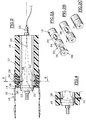
- Figure 1 there is shown the coaxial mounting of the metal support cylinder 10, the intermediate sleeve 12, the thin sleeve 14 on which we have shown under the reference 16, either a rubber lining engraved with the image 18, or an actual photograph with the same image, according to the choice of the user and the needs dictated by the type of image.
- the central nozzle 20 for introducing compressed air is generally formed coaxially with one of the axes of the metal support cylinder.
- the support cylinder is made of metal and the intermediate sleeve as well as the thin sleeve are made of polymer material.
- the intermediate sleeve is produced according to the teaching of French patent application No. 94 06417.
- the metal support cylinder 10 comprises nozzles 22 distributed regularly, along a through circle, at the periphery of said cylinder in order to put the interior of this cylinder into communication with the outside, the air path 24 being symbolized by arrows 26.
- the intermediate sleeve 12 comprises a ring 28 fixed in rotation relative to the body of the intermediate sleeve and a movable ring 29, free to rotate on the fixed ring 28.
- the fixed ring has an outside diameter equal to that of the outside diameter of the sleeve, and an internal diameter equal to the diameter of a projection 30 formed at the end of the intermediate body.
- This fixed ring has a reduced diameter over a part of its length, equal, apart from play, to the inside diameter of the movable ring.
- the movable ring 29 has an outside diameter equal to the outside diameter of the body of the intermediate sleeve and to the outside diameter of the fixed ring in its non-reduced diameter portion.
- Nozzles 34, 36 are machined respectively through the thickness of the reduced diameter portion of the fixed ring 28 and through the thickness of the movable ring 29.
- the sleeve body also carries nozzles 38 in the part located to the right of the projection.
- this intermediate sleeve is carried out according to steps 2A to 2C.
- the movable ring 29 is threaded onto the reduced diameter part of the fixed ring 28 and then the fixed ring is mounted with its movable ring coaxially with the projection 30 of the corsp of the intermediate cylinder by interposing a fixing means such as a cyanoacrylate type adhesive sold under the name "loctite" taking the precaution of making the nozzles 34 of the fixed ring coincide with the nozzles 38 of the projection 30 of the intermediate sleeve.
- the movable ring 29 can rotate relative to the reduced diameter portion of the fixed ring while this same fixed ring is immobilized in translation, thus retaining the mobile ring.
- FIG. 3A it can be seen that the nozzles 22, 34, 36 and 38 are distributed along identical angular sectors so that in a given position, they can be aligned.
- the assembly of such an assembly is carried out by introducing pressurized air through the nozzle 20 which passes through the nozzles 22 of the support cylinder 10.
- the operator threads the intermediate sleeve 12 through the end of the cylinder provided with these nozzles 22.
- the air film allows easy insertion of this intermediate sleeve.
- the ring 29 is in the position shown in FIG. 3B, that is to say a position in which the nozzles 36 and 38 are in coincidence by manufacture but in which the nozzles 34 are not in coincidence with the nozzles 36 and 38.
- the intermediate sleeve once inserted as far as possible and correctly positioned on the metal support cylinder, is locked on this support cylinder by rotation of the movable ring 29 in order to bring the nozzles 36 and 38 in coincidence with the nozzles 34, c ' that is to say in the position of FIG. 3A.
- the thin sleeve 14 is then threaded in turn on the intermediate sleeve 12, because the air which escapes through the four series of nozzles forms an air film which allows a very easy assembly.
- the operator can then mount a new thin sleeve.
- the intermediate sleeve is removed by rotation of the ring and the operator mounts, after removal of the sleeve used, the new sleeve.
- the metal support cylinder should also be changed.
- FIG 4 there is shown a variant of the intermediate sleeve in which the ring has been removed and replaced by threaded cylindrical inserts 40 in which threaded plugs 42 can be screwed.
- Threaded plugs play the same role as the ring and if they are a little less flexible to use, their cost is lower.
- the ring is formed in a projection machined from the inner periphery of the intermediate sleeve, but such a projection can be formed from the outer periphery.
- positioning indexes can be displayed to facilitate assembly and prior adjustment operations.
- the intermediate sleeves are produced according to the teaching of patent application FR-A-94 06417.
- Each sleeve comprises a succession of layers of honeycomb material preferably embedded in a resin matrix.
- the manufacturing support is a metal cylinder rectified to the diameter of the subsequent support cylinder.
- the peripheral inner surface has a polished appearance.
- the outer surface is ground to the exact diameter allowing tight fitting of the thin sleeve.
- composition of the resin is adapted to give the sleeve a calculated shrinkage which ensures a tight fitting radially.
- a known mechanical machining is provided and within the reach of those skilled in the art.
Landscapes
- Manufacture Or Reproduction Of Printing Formes (AREA)
- Rotary Presses (AREA)
- Printing Plates And Materials Therefor (AREA)
- Rolls And Other Rotary Bodies (AREA)
- Discharging, Photosensitive Material Shape In Electrophotography (AREA)
- Delivering By Means Of Belts And Rollers (AREA)
- Rollers For Roller Conveyors For Transfer (AREA)
Applications Claiming Priority (2)
| Application Number | Priority Date | Filing Date | Title |
|---|---|---|---|
| FR9413801 | 1994-11-14 | ||
| FR9413801A FR2726786A1 (fr) | 1994-11-14 | 1994-11-14 | Agencement et manchon intercalaire porte-manchon mince notamment pour machine d'impression flexographique |
Publications (2)
| Publication Number | Publication Date |
|---|---|
| EP0711665A1 true EP0711665A1 (de) | 1996-05-15 |
| EP0711665B1 EP0711665B1 (de) | 1999-03-10 |
Family
ID=9468909
Family Applications (1)
| Application Number | Title | Priority Date | Filing Date |
|---|---|---|---|
| EP95450016A Expired - Lifetime EP0711665B1 (de) | 1994-11-14 | 1995-11-13 | Hülsenanordnung und Zwischenhülse zum Tragen einer Dünnhülse, insbesondere für eine Flexodruckmaschine |
Country Status (9)
| Country | Link |
|---|---|
| US (1) | US5706731A (de) |
| EP (1) | EP0711665B1 (de) |
| JP (1) | JPH08207235A (de) |
| AT (1) | ATE177366T1 (de) |
| CA (1) | CA2162657A1 (de) |
| DE (1) | DE69508184T2 (de) |
| DK (1) | DK0711665T3 (de) |
| ES (1) | ES2131786T3 (de) |
| FR (1) | FR2726786A1 (de) |
Cited By (9)
| Publication number | Priority date | Publication date | Assignee | Title |
|---|---|---|---|---|
| EP0753416A1 (de) * | 1995-07-10 | 1997-01-15 | POLYWEST KUNSTSTOFFTECHNIK Saueressig & Partner GmbH & Co. KG | Verfahren zur Herstellung einer nahtlosen Druckhülse, insbesondere für einen Flexodruckzylinder |
| FR2785226A1 (fr) * | 1998-11-02 | 2000-05-05 | Polyfibron Technologies Sa | Manchon intermediaire pour cylindre d'impression |
| US6283026B1 (en) | 1998-11-02 | 2001-09-04 | Polybribron Technologies S.A. | Device for automatically blocking air passages in cylinder, specifically for support cylinders and compensation mantles |
| WO2001070505A3 (en) * | 2000-03-17 | 2002-03-07 | Day Int Inc | Bridge mandrel for flexographic printing systems |
| US6647879B1 (en) | 2002-12-26 | 2003-11-18 | Paper Converting Machine Co. | Bridge sleeve for printing apparatus |
| WO2004018210A1 (en) * | 2002-08-09 | 2004-03-04 | T.C.M. Tecno Converting Machinery Srl | Device and method for mounting/demounting sleeves on/from a printing cylinder, particularly for a rotary printing press |
| FR2922479A1 (fr) * | 2007-10-19 | 2009-04-24 | Philippe Francille | Procede de montage d'un manchon mince sur un cylindre porteur de machine d'impression, manchon transfert adapte |
| EP2093059A3 (de) * | 2008-02-21 | 2010-05-05 | E. I. du Pont de Nemours and Company | Erweiterte Druckformhülse und Verfahren zur Herstellung einer Druckform aus dieser Hülse |
| WO2019172769A1 (en) * | 2018-03-09 | 2019-09-12 | Apex Europe B.V. | An apparatus for flexographic printing and a method of forming the apparatus |
Families Citing this family (39)
| Publication number | Priority date | Publication date | Assignee | Title |
|---|---|---|---|---|
| DE19523441A1 (de) * | 1995-06-28 | 1997-01-02 | Kurz Leonhard Fa | Prägewalze für eine Prägevorrichtung |
| US5819657A (en) * | 1996-03-11 | 1998-10-13 | Ermino Rossini, Spa | Air carrier spacer sleeve for a printing cylinder |
| CA2224762A1 (en) * | 1998-01-23 | 1999-07-23 | Bob Erbstein | Variable cutoff press unit |
| US5987748A (en) * | 1998-07-31 | 1999-11-23 | Monarch Marking Systems, Inc. | Method of making ink roller assembly |
| US5953992A (en) * | 1998-07-31 | 1999-09-21 | Monarch Marking Systems, Inc. | Method of making ink roller assembly |
| US6425327B1 (en) * | 1999-08-12 | 2002-07-30 | E. I. Du Pont De Nemours And Company | Method for forming a cylindrical photosensitive element |
| US6360662B1 (en) | 2000-03-17 | 2002-03-26 | Day International, Inc. | Bridge mandrel for flexographic printing systems |
| DE10066292B4 (de) * | 2000-05-17 | 2014-12-11 | Manroland Web Systems Gmbh | Formatvariable Rollenoffsetdruckmaschine und Verfahren zur Herstellung formatvariabler Oberflächen |
| DE10024001B4 (de) | 2000-05-17 | 2014-11-13 | Manroland Web Systems Gmbh | Formatvariable Rollenoffsetdruckmaschine und Verfahren zur Herstellung formatvariabler Oberflächen |
| US6401613B1 (en) * | 2000-05-23 | 2002-06-11 | Xymid, Llc | Printing cylinder sleeve assembly |
| DE10046559A1 (de) | 2000-09-19 | 2002-04-04 | Akl Flexo Technik Gmbh | Druckklischee-Montagesystem |
| EP1228870A1 (de) | 2001-02-06 | 2002-08-07 | Hannethane N.V. | Beschichteter Zylinder mit Luftkanälen und Verfahren zum Beschichten eines Zylinders |
| US7011021B2 (en) * | 2001-09-10 | 2006-03-14 | Day International, Inc. | Printing blanket sleeve with replaceable printing surface |
| FR2834802B1 (fr) * | 2002-01-11 | 2004-06-04 | Macdermid Graphic Arts Sa | Procede de fabrication d'une plaque de flexographie et plaque de flexographie obtenue par ce procede |
| US6799510B2 (en) * | 2002-05-02 | 2004-10-05 | New Hudson Corporation | Thin-walled bridge mandrel |
| AU2002302659A1 (en) * | 2002-05-10 | 2003-11-11 | Comexi, S.A. | Device for removing printing cylinder sleeves |
| FR2843071B1 (fr) * | 2002-08-02 | 2005-02-18 | Komori Chambon | Perfectionnements aux machines d'impression |
| DE10306196B3 (de) * | 2003-02-13 | 2004-10-07 | Windmöller & Hölscher Kg | Farbübertragungswalze |
| US7530938B2 (en) * | 2003-07-01 | 2009-05-12 | Illinois Tool Works Inc. | Pneumatic roller for passing film with attachments through rollers of machine |
| DE102004031645A1 (de) * | 2003-07-25 | 2005-02-10 | Heidelberger Druckmaschinen Ag | Aufzugsvorrichtung für hülsenförmige Aufzüge |
| US20050205824A1 (en) * | 2004-03-18 | 2005-09-22 | Osborne Charles A | Segmented ball control valve with universal end connections |
| DE102004022181B3 (de) * | 2004-05-05 | 2005-11-03 | Man Roland Druckmaschinen Ag | Vorrichtung zum Verbinden einer inneren Druckhülse mit einer äußeren Druckhülse zu einer Einheit und zum Trennen der beiden Druckhülsen |
| US7124685B2 (en) * | 2004-05-18 | 2006-10-24 | Meca & Technology Machine, Inc. | Internally piped print cylinder and method for making same |
| ITFI20040226A1 (it) * | 2004-11-08 | 2005-02-08 | Om Futura S P A | Dispositivo e procedimento per la rimozione della camicia dai rulli cliche' in macchine per stampa |
| US20070125651A1 (en) * | 2005-12-02 | 2007-06-07 | Buckley Paul W | Electroform, methods of making electroforms, and products made from electroforms |
| US20070126148A1 (en) * | 2005-12-02 | 2007-06-07 | General Electric Company | Microstructured embossing drum and articles made therefrom |
| US20070125652A1 (en) * | 2005-12-02 | 2007-06-07 | Buckley Paul W | Electroform, methods of making electroforms, and products made from electroforms |
| US20070125248A1 (en) * | 2005-12-02 | 2007-06-07 | Coyle Dennis J | Embossing drum system with removable outer sleeve and methods of use |
| US20070125653A1 (en) * | 2005-12-02 | 2007-06-07 | Coyle Dennis J | Multilayer electroform, methods of making multilayer electroforms, and products made therefrom |
| US20070125655A1 (en) * | 2005-12-02 | 2007-06-07 | Buckley Paul W | Electroform, methods of making electroforms, and products made from electroforms |
| US20070125654A1 (en) * | 2005-12-02 | 2007-06-07 | Buckley Paul W | Electroform, methods of making electroforms, and products made from electroforms |
| US20070126144A1 (en) * | 2005-12-02 | 2007-06-07 | Yadong Jin | Polish/texture thermoplastic film and method for making the same |
| EP2463112B1 (de) * | 2008-11-26 | 2013-08-07 | Agfa Graphics N.V. | Hülsen und Hülsensegmente für den Flexodruck |
| US20110155006A1 (en) * | 2009-12-31 | 2011-06-30 | Bryce Corporation | Interlocking printing sleeves |
| US8596197B2 (en) | 2011-06-07 | 2013-12-03 | Goss International Americas, Inc. | Printing press cylinder assembly and method of installing sleeves on a mandrel of a printing press cylinder assembly |
| PL3243660T3 (pl) * | 2016-05-09 | 2019-03-29 | Flint Group Germany Gmbh | Cylinder z częściowo gazoprzepuszczalną powierzchnią |
| KR102190980B1 (ko) * | 2019-03-12 | 2020-12-15 | 부산대학교 산학협력단 | 패턴 성형 롤의 이음매 없는 슬리브 체결 장치 및 방법 |
| WO2021096484A1 (en) * | 2019-11-11 | 2021-05-20 | Hewlett-Packard Development Company, L.P. | Primer apparatus |
| EP4084913B1 (de) | 2019-12-31 | 2024-02-28 | 3M Innovative Properties Company | Düsenbeschichtung auf luftunterstützter schale |
Citations (3)
| Publication number | Priority date | Publication date | Assignee | Title |
|---|---|---|---|---|
| DE2542748A1 (de) * | 1974-09-26 | 1976-04-15 | Buckley M A Engraving Ltd | Druckwalze fuer anilindruck und verfahren zu ihrem zusammenbau |
| US5216954A (en) * | 1991-10-24 | 1993-06-08 | Thompson William L | Multi-section mountable sleeves and methods for mounting and dismounting same |
| EP0546973A1 (de) * | 1991-12-11 | 1993-06-16 | Jean Francille | Plattenhülse für flexographische Druckzylinder |
Family Cites Families (4)
| Publication number | Priority date | Publication date | Assignee | Title |
|---|---|---|---|---|
| US4378622A (en) * | 1977-11-10 | 1983-04-05 | Dayco Corporation | Method of making compressible printing roller |
| US4178664A (en) * | 1978-07-17 | 1979-12-18 | Mcloughlin Nelson E | Roller with replaceable sleeve |
| US4381709A (en) * | 1980-06-13 | 1983-05-03 | Robert Katz | Printing roller with removable cylinder |
| US5481975A (en) * | 1994-10-03 | 1996-01-09 | Schulz; Werner | Printing cylinder mandrel and image carrier sleeve |
-
1994
- 1994-11-14 FR FR9413801A patent/FR2726786A1/fr active Granted
-
1995
- 1995-11-10 CA CA002162657A patent/CA2162657A1/fr not_active Abandoned
- 1995-11-13 DE DE69508184T patent/DE69508184T2/de not_active Expired - Lifetime
- 1995-11-13 EP EP95450016A patent/EP0711665B1/de not_active Expired - Lifetime
- 1995-11-13 ES ES95450016T patent/ES2131786T3/es not_active Expired - Lifetime
- 1995-11-13 AT AT95450016T patent/ATE177366T1/de not_active IP Right Cessation
- 1995-11-13 DK DK95450016T patent/DK0711665T3/da active
- 1995-11-14 US US08/555,712 patent/US5706731A/en not_active Expired - Fee Related
- 1995-11-14 JP JP7319487A patent/JPH08207235A/ja active Pending
Patent Citations (3)
| Publication number | Priority date | Publication date | Assignee | Title |
|---|---|---|---|---|
| DE2542748A1 (de) * | 1974-09-26 | 1976-04-15 | Buckley M A Engraving Ltd | Druckwalze fuer anilindruck und verfahren zu ihrem zusammenbau |
| US5216954A (en) * | 1991-10-24 | 1993-06-08 | Thompson William L | Multi-section mountable sleeves and methods for mounting and dismounting same |
| EP0546973A1 (de) * | 1991-12-11 | 1993-06-16 | Jean Francille | Plattenhülse für flexographische Druckzylinder |
Cited By (13)
| Publication number | Priority date | Publication date | Assignee | Title |
|---|---|---|---|---|
| EP0753416A1 (de) * | 1995-07-10 | 1997-01-15 | POLYWEST KUNSTSTOFFTECHNIK Saueressig & Partner GmbH & Co. KG | Verfahren zur Herstellung einer nahtlosen Druckhülse, insbesondere für einen Flexodruckzylinder |
| FR2785226A1 (fr) * | 1998-11-02 | 2000-05-05 | Polyfibron Technologies Sa | Manchon intermediaire pour cylindre d'impression |
| US6283026B1 (en) | 1998-11-02 | 2001-09-04 | Polybribron Technologies S.A. | Device for automatically blocking air passages in cylinder, specifically for support cylinders and compensation mantles |
| AU770336B2 (en) * | 2000-03-17 | 2004-02-19 | Day International, Inc. | Bridge mandrel for flexographic printing systems |
| WO2001070505A3 (en) * | 2000-03-17 | 2002-03-07 | Day Int Inc | Bridge mandrel for flexographic printing systems |
| WO2004018210A1 (en) * | 2002-08-09 | 2004-03-04 | T.C.M. Tecno Converting Machinery Srl | Device and method for mounting/demounting sleeves on/from a printing cylinder, particularly for a rotary printing press |
| US6647879B1 (en) | 2002-12-26 | 2003-11-18 | Paper Converting Machine Co. | Bridge sleeve for printing apparatus |
| FR2922479A1 (fr) * | 2007-10-19 | 2009-04-24 | Philippe Francille | Procede de montage d'un manchon mince sur un cylindre porteur de machine d'impression, manchon transfert adapte |
| WO2009053655A1 (fr) * | 2007-10-19 | 2009-04-30 | Philippe Francille | Procede de montage d'un manchon mince sur un cylindre porteur de machine d'impression, manchon transfert adapte |
| EP2093059A3 (de) * | 2008-02-21 | 2010-05-05 | E. I. du Pont de Nemours and Company | Erweiterte Druckformhülse und Verfahren zur Herstellung einer Druckform aus dieser Hülse |
| EP2251199A1 (de) * | 2008-02-21 | 2010-11-17 | E. I. du Pont de Nemours and Company | Verfahren zur Herstellung einer Druckform aus einer Hülse |
| WO2019172769A1 (en) * | 2018-03-09 | 2019-09-12 | Apex Europe B.V. | An apparatus for flexographic printing and a method of forming the apparatus |
| NL2020561B1 (en) * | 2018-03-09 | 2019-09-13 | Apex Europe B V | An Apparatus for Flexographic Printing and A Method of Forming and Operating the Apparatus |
Also Published As
| Publication number | Publication date |
|---|---|
| JPH08207235A (ja) | 1996-08-13 |
| CA2162657A1 (fr) | 1996-05-15 |
| FR2726786B1 (de) | 1997-02-07 |
| US5706731A (en) | 1998-01-13 |
| DE69508184T2 (de) | 1999-10-14 |
| FR2726786A1 (fr) | 1996-05-15 |
| ES2131786T3 (es) | 1999-08-01 |
| DE69508184D1 (de) | 1999-04-15 |
| EP0711665B1 (de) | 1999-03-10 |
| ATE177366T1 (de) | 1999-03-15 |
| DK0711665T3 (da) | 1999-09-27 |
Similar Documents
| Publication | Publication Date | Title |
|---|---|---|
| EP0711665B1 (de) | Hülsenanordnung und Zwischenhülse zum Tragen einer Dünnhülse, insbesondere für eine Flexodruckmaschine | |
| JP3223788B2 (ja) | 回転式印刷胴用同心二重版円筒 | |
| JPH0664136A (ja) | 版胴を備えた印刷装置および版胴の印刷準備のための方法 | |
| FR2744389A1 (fr) | Groupe d'impression permettant un changement de plaques d'impression en marche | |
| FR2751268A1 (fr) | Rouleau de transfert d'encre pour l'unite d'encrage d'une machine offset a imprimer et procede pour fabriquer ce rouleau | |
| EP0132859A2 (de) | Rotationsmehrfarbendruckmaschine | |
| FR2518455A1 (fr) | Imprimeuse flexographique | |
| EP0625466B1 (de) | Vorrichtung zum Auftragen von Bildern in einer Sicherheitsdruckmaschine | |
| EP0665104B1 (de) | Verfahren und Vorrichtung zum Nacheinander Bedrucken von Bogen | |
| FR2737154A1 (fr) | Cylindre comportant un revetement d'impression pour l'impression offset | |
| FR2639581A1 (fr) | Chariot porte-groupe d'impression pour une station d'impression dans des machines rotatives | |
| ITMO960114A1 (it) | Dispositivo per decorare piastrelle ceramiche | |
| FR2836414A1 (fr) | Dispositif de vernissage | |
| EP1773593B1 (de) | Verfahren und vorrichtung zur herstellung einer ophthalmischen linse | |
| EP0976532A1 (de) | Form für Fahrzeugreifen, und geeignete Vulkanisierpresse zum Aufnehmen einer solchen Form | |
| FR2702996A1 (fr) | Appareil d'impression offset à cassette amovible. | |
| EP2209633A1 (de) | Verfahren zur befestigung einer dünnwandigen hülse an einem druckpressenformzylinder und geeignete transferhülse | |
| FR2785226A1 (fr) | Manchon intermediaire pour cylindre d'impression | |
| EP1230089A1 (de) | Farbklischee einer rotationsdruckmaschine | |
| FR2953447A1 (fr) | Groupe d'impression d'une machine d'impression et procede de changement des plaques d'impression | |
| EP0888577A1 (de) | Industrielles verfahren und gerät zur erzeugung von aufgehellten oder vor-aufgehellten offset-druckplatten | |
| EP1038670B1 (de) | Verfahren zur Herstellung eines photopolymeren Druckbands für den Flexodruck | |
| KR20080077089A (ko) | 프린터 | |
| FR2527518A1 (fr) | Machine a imprimer dont les cylindres comportent des bagues d'espacement | |
| FR2927837A1 (fr) | Unite d'impression pour presse rotative. |
Legal Events
| Date | Code | Title | Description |
|---|---|---|---|
| PUAI | Public reference made under article 153(3) epc to a published international application that has entered the european phase |
Free format text: ORIGINAL CODE: 0009012 |
|
| AK | Designated contracting states |
Kind code of ref document: A1 Designated state(s): AT BE DE DK ES GB IT LU NL SE |
|
| 17P | Request for examination filed |
Effective date: 19961002 |
|
| GRAG | Despatch of communication of intention to grant |
Free format text: ORIGINAL CODE: EPIDOS AGRA |
|
| 17Q | First examination report despatched |
Effective date: 19980427 |
|
| GRAG | Despatch of communication of intention to grant |
Free format text: ORIGINAL CODE: EPIDOS AGRA |
|
| GRAH | Despatch of communication of intention to grant a patent |
Free format text: ORIGINAL CODE: EPIDOS IGRA |
|
| GRAH | Despatch of communication of intention to grant a patent |
Free format text: ORIGINAL CODE: EPIDOS IGRA |
|
| GRAA | (expected) grant |
Free format text: ORIGINAL CODE: 0009210 |
|
| AK | Designated contracting states |
Kind code of ref document: B1 Designated state(s): AT BE DE DK ES GB IT LU NL SE |
|
| REF | Corresponds to: |
Ref document number: 177366 Country of ref document: AT Date of ref document: 19990315 Kind code of ref document: T |
|
| REF | Corresponds to: |
Ref document number: 69508184 Country of ref document: DE Date of ref document: 19990415 |
|
| GBT | Gb: translation of ep patent filed (gb section 77(6)(a)/1977) |
Effective date: 19990601 |
|
| REG | Reference to a national code |
Ref country code: ES Ref legal event code: FG2A Ref document number: 2131786 Country of ref document: ES Kind code of ref document: T3 |
|
| REG | Reference to a national code |
Ref country code: DK Ref legal event code: T3 |
|
| PLBE | No opposition filed within time limit |
Free format text: ORIGINAL CODE: 0009261 |
|
| STAA | Information on the status of an ep patent application or granted ep patent |
Free format text: STATUS: NO OPPOSITION FILED WITHIN TIME LIMIT |
|
| 26N | No opposition filed | ||
| PGFP | Annual fee paid to national office [announced via postgrant information from national office to epo] |
Ref country code: LU Payment date: 20001205 Year of fee payment: 6 |
|
| PG25 | Lapsed in a contracting state [announced via postgrant information from national office to epo] |
Ref country code: LU Free format text: LAPSE BECAUSE OF NON-PAYMENT OF DUE FEES Effective date: 20011113 |
|
| REG | Reference to a national code |
Ref country code: GB Ref legal event code: IF02 |
|
| PGFP | Annual fee paid to national office [announced via postgrant information from national office to epo] |
Ref country code: DK Payment date: 20030312 Year of fee payment: 8 |
|
| PGFP | Annual fee paid to national office [announced via postgrant information from national office to epo] |
Ref country code: AT Payment date: 20030313 Year of fee payment: 8 |
|
| PGFP | Annual fee paid to national office [announced via postgrant information from national office to epo] |
Ref country code: SE Payment date: 20030318 Year of fee payment: 8 |
|
| PGFP | Annual fee paid to national office [announced via postgrant information from national office to epo] |
Ref country code: NL Payment date: 20030328 Year of fee payment: 8 Ref country code: BE Payment date: 20030328 Year of fee payment: 8 |
|
| PG25 | Lapsed in a contracting state [announced via postgrant information from national office to epo] |
Ref country code: AT Free format text: LAPSE BECAUSE OF NON-PAYMENT OF DUE FEES Effective date: 20031113 |
|
| PG25 | Lapsed in a contracting state [announced via postgrant information from national office to epo] |
Ref country code: SE Free format text: LAPSE BECAUSE OF NON-PAYMENT OF DUE FEES Effective date: 20031114 |
|
| PG25 | Lapsed in a contracting state [announced via postgrant information from national office to epo] |
Ref country code: BE Free format text: LAPSE BECAUSE OF NON-PAYMENT OF DUE FEES Effective date: 20031130 |
|
| PG25 | Lapsed in a contracting state [announced via postgrant information from national office to epo] |
Ref country code: DK Free format text: LAPSE BECAUSE OF NON-PAYMENT OF DUE FEES Effective date: 20031201 |
|
| BERE | Be: lapsed |
Owner name: *FRANCILLE PHILIPPE Effective date: 20031130 Owner name: *FRANCILLE JEAN Effective date: 20031130 |
|
| PG25 | Lapsed in a contracting state [announced via postgrant information from national office to epo] |
Ref country code: NL Free format text: LAPSE BECAUSE OF NON-PAYMENT OF DUE FEES Effective date: 20040601 |
|
| EUG | Se: european patent has lapsed | ||
| REG | Reference to a national code |
Ref country code: DK Ref legal event code: EBP |
|
| NLV4 | Nl: lapsed or anulled due to non-payment of the annual fee |
Effective date: 20040601 |
|
| PGFP | Annual fee paid to national office [announced via postgrant information from national office to epo] |
Ref country code: ES Payment date: 20061114 Year of fee payment: 12 |
|
| REG | Reference to a national code |
Ref country code: ES Ref legal event code: FD2A Effective date: 20071114 |
|
| PG25 | Lapsed in a contracting state [announced via postgrant information from national office to epo] |
Ref country code: ES Free format text: LAPSE BECAUSE OF NON-PAYMENT OF DUE FEES Effective date: 20071114 |
|
| PG25 | Lapsed in a contracting state [announced via postgrant information from national office to epo] |
Ref country code: IT Free format text: LAPSE BECAUSE OF NON-PAYMENT OF DUE FEES Effective date: 20071113 |
|
| PGRI | Patent reinstated in contracting state [announced from national office to epo] |
Ref country code: IT Effective date: 20110616 |
|
| REG | Reference to a national code |
Ref country code: DE Ref legal event code: R082 Ref document number: 69508184 Country of ref document: DE Representative=s name: MEISSNER, BOLTE & PARTNER GBR, DE |
|
| PGFP | Annual fee paid to national office [announced via postgrant information from national office to epo] |
Ref country code: DE Payment date: 20121018 Year of fee payment: 18 |
|
| PGFP | Annual fee paid to national office [announced via postgrant information from national office to epo] |
Ref country code: GB Payment date: 20121004 Year of fee payment: 18 Ref country code: IT Payment date: 20121107 Year of fee payment: 18 |
|
| GBPC | Gb: european patent ceased through non-payment of renewal fee |
Effective date: 20131113 |
|
| REG | Reference to a national code |
Ref country code: DE Ref legal event code: R119 Ref document number: 69508184 Country of ref document: DE Effective date: 20140603 |
|
| PG25 | Lapsed in a contracting state [announced via postgrant information from national office to epo] |
Ref country code: DE Free format text: LAPSE BECAUSE OF NON-PAYMENT OF DUE FEES Effective date: 20140603 Ref country code: IT Free format text: LAPSE BECAUSE OF NON-PAYMENT OF DUE FEES Effective date: 20131113 |
|
| PG25 | Lapsed in a contracting state [announced via postgrant information from national office to epo] |
Ref country code: GB Free format text: LAPSE BECAUSE OF NON-PAYMENT OF DUE FEES Effective date: 20131113 |