EP0711697A1 - Dispositif pour établir la disponibilité pour rouler par gravité et/ou accoupler des véhicules guidés sur une voie - Google Patents
Dispositif pour établir la disponibilité pour rouler par gravité et/ou accoupler des véhicules guidés sur une voie Download PDFInfo
- Publication number
- EP0711697A1 EP0711697A1 EP95250271A EP95250271A EP0711697A1 EP 0711697 A1 EP0711697 A1 EP 0711697A1 EP 95250271 A EP95250271 A EP 95250271A EP 95250271 A EP95250271 A EP 95250271A EP 0711697 A1 EP0711697 A1 EP 0711697A1
- Authority
- EP
- European Patent Office
- Prior art keywords
- vehicle
- coupling
- coupling elements
- vehicles
- signal
- Prior art date
- Legal status (The legal status is an assumption and is not a legal conclusion. Google has not performed a legal analysis and makes no representation as to the accuracy of the status listed.)
- Granted
Links
Images

Classifications
-
- B—PERFORMING OPERATIONS; TRANSPORTING
- B61—RAILWAYS
- B61G—COUPLINGS; DRAUGHT AND BUFFING APPLIANCES
- B61G7/00—Details or accessories
- B61G7/04—Coupling or uncoupling by means of trackside apparatus
-
- B—PERFORMING OPERATIONS; TRANSPORTING
- B61—RAILWAYS
- B61G—COUPLINGS; DRAUGHT AND BUFFING APPLIANCES
- B61G7/00—Details or accessories
Definitions
- Track-side devices for automatic uncoupling of railway vehicles to be disconnected have therefore become known (DE-A1-38 19 388), in which a track-side ejector lifts the coupling eye of the respective suspended coupling from the coupling partner's coupling hook while two vehicles are passing.
- the coupling must first be made ready for solution (so-called make-long), which continues to be done manually.
- make-long The subsequent attachment of the coupling eyes and the subsequent tightening of the couplings (shortening) must also be carried out by hand.
- the known device must have the speed of the freight cars when releasing the couplings and then return to a starting position. This requires a high level of technical effort and limits the permissible pull-off speed.
- the object of the present invention is to provide a vehicle-side device for actuating the vehicle's own clutches, in particular for establishing the readiness to run, by means of which the clutch to be actuated can be reliably selected regardless of the orientation of the individual vehicles.
- a device for producing the readiness to run and / or ready to couple of track-bound vehicles with a controllable coupling at each end of the vehicle, which is connected to an in-vehicle signal line via an identification unit, and with coupling elements for coupling the in-vehicle signal lines with Coupling elements and / or signal lines of adjacent vehicles to form two continuous signal paths, into which selection signals for selecting the clutches to be controlled can be fed in for all vehicles involved, the identification unit selecting those selection signals which are intended for the respective vehicle, and the coupling elements being arranged in this way and can be coupled that, regardless of the individual orientation of the vehicles seen in a reference direction, all rear clutches via the one signal path and all front clutches can be selected or controlled via the other signal path.
- Control signals for transferring the couplings into a released and / or coupling-ready position can also preferably be fed into the signal paths.
- the for the switching movements of the Clutches of necessary energy can be taken from a vehicle-side, preferably pneumatic, energy store, which is connected to a common compressed air supply line when the vehicles are coupled.
- the vehicles can preferably be self-sufficient in terms of energy in that the vehicle-specific energy supply is provided by a generator or compressor with a connected energy store that is driven while driving via a vehicle axle.
- An actuator for switching the clutch is preferably controlled electrically, the energy required for the actuator being able to be taken from an auxiliary power source on the vehicle.
- the device can be used not only to bring the clutch into the butt position while the vehicle is being fed in, but also, through delayed execution of the control signal, for the subsequent establishment of the coupling readiness after the vehicle has, for example, passed into free operation in a maneuvering system.
- a plausibility check can be used to determine the free running of the vehicle, which, for example, deduces a released brake from the venting of the brake energy store or signals the moment when the control paths are separated.
- the coupling elements are arranged and can be coupled such that, seen in a reference direction (for example in the direction of travel), all the couplings of the same (for example front) vehicle ends on a common signal line formed by the vehicle Signal path are connected. Therefore, the individual orientation of the vehicle is not important. With a rotation of the vehicle by 180 ° (U-turn) z.
- the signal paths each form a serial data bus, via which at least the selection signals are transmitted.
- a major advantage of the invention is thus the possibility of a central feed of the selection signals for all vehicles involved. This feed-in can preferably take place via radio or the double locomotive.
- the actual vehicle-specific control signals which are selected by means of the identification unit, can preferably also be fed to the selected clutch or its actuator system via the signal paths. Further information, for example waybill information, fault reports or shock sensor protocols, can preferably also be transmitted to the individual vehicles for storage and / or further processing via the common signal paths.
- the coupling elements of each vehicle end are arranged symmetrically to a vertical plane (longitudinal section plane) containing the vehicle longitudinal axis and congruent with the coupling elements of the respective signal lines arranged at the other vehicle end. This results in a fully symmetrical arrangement of the coupling elements, so that they can interact directly with the coupling elements of the adjacent vehicles in both possible vehicle orientations without additional connecting means (e.g. cables).
- a particularly robust embodiment of the device according to the invention provides that the coupling elements of a vehicle end are contained in a coupling plug which can preferably be coupled together with the controllable coupling of the respective coupling partner.
- the coupling elements are electrical or optical connection elements.
- the coupling elements can be coupled inductively.
- the vehicle F shown in FIG. 1 is coupled to controllable automatic clutches ZAK1 at the first vehicle end E1 and ZAK2 at the second vehicle end E2 with clutches of neighboring vehicles, which are not shown in detail.
- the clutches ZAK1, ZAK2 can be moved by an actuator A1, A2 in the ready state or in the ready state and in the butt position. Only the actuator A1 is explained in detail below, because the actuator A2 is constructed accordingly.
- Energy supply lines L1 to L3 are used to supply power to the actuators A1, A2. When the vehicles are coupled, they are looped through all vehicles up to the locomotive and are supplied with energy there.
- the necessary energy can be generated individually for the vehicle by the rolling movement of a wheel R driving a generator and / or compressor and the energy generated by it being stored in energy stores ES1, ES2.
- the Actuator A1 takes the actuating energy required to change the clutch position from the energy store ES1, which is connected to the compressed air line L1 via a valve control V1 and a check valve RV.
- the clutch ZAK1 is actuated by means of an actuator S1 which is articulated on the piston of an actuator cylinder Z1.
- a relay R1 or an output circuit forwards control commands of a vehicle device FG on the output side to the valve control V1 in order to move the piston in the cylinder Z1 as required and thus actuate the clutch ZAK1.
- the control commands for the clutch ZAK1 are transmitted via a first in-vehicle signal line SL1 (described in more detail below) and for the clutch ZAK2 via a second in-vehicle signal line SL2.
- SL1 first in-vehicle signal line
- SL2 second in-vehicle signal line
- identification unit ID which only signals to the vehicle device FG or to the actuators A1, A2 via the signal lines SL1, SL2
- Control of the clutches ZAK1, ZAK2 passes on, which are selected as intended for the vehicle F.
- the selection can be made, for example, in that signals FSIG1, FSIG2 intended for vehicle F are provided with an identification identifier.
- the identification unit compares this identifier with a vehicle-specific identifier (reference), for example the car number WN1.
- a vehicle-specific identifier for example the car number WN1.
- the signals FSIG1, FSIG2 can only be used to select the coupling of a vehicle to be addressed (selection signals) via the signal paths and signals for controlling the respective actuators can be transmitted via a separate, continuous data bus.
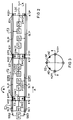
- FIG. 2 schematically shows three vehicles F1, F2, F3 with the basic structure explained in FIG.
- Each vehicle has coupling elements K12, K22 (F1), K11 ', K12', K21 'arranged symmetrically to a vertical plane (longitudinal sectional plane) LSE containing the vehicle longitudinal axis LA, K22 '(F2); K11 '', Kl2 '', K2l '', K22 '' (F3).
- the coupling elements limit vehicle signal lines SL1, SL2; SL1 ', SL2'; SL1 '', SL2 '.
- the coupling elements K21 'and K22' assigned to a vehicle's own signal line (e.g.
- the coupling elements are designed as electrical connectors, so that, for example, the coupling element K22 'is electrically conductively connected to the corresponding coupling element K21''of the adjacent vehicle F3 in the coupled state.
- the vehicle-specific signal lines SL1, SL1 ', SL1'' form a first signal path STP1, which runs through all the participating and coupled vehicles F1, F2, F3.
- Signals SIG1, SIG2 for all vehicles F1, F2, F3 involved are fed centrally into the signal paths STP1, STP2.
- the central feed-in STE can take place, for example, from a two-way locomotive, not shown, or a radio receiver.
- the identification unit of the individual vehicles e.g. ID '; F2 selects the signals FSIG1, FSIG2 contained in the signals SIG1, SIG2, which e.g. B. are intended for the vehicle F2.
- vehicle-specific control signals - which can be components of the signals FSIG1, FSIG2 - the actuators A1, A2 are activated as required in the manner described at the beginning.
- the rear or front clutch can be selected via the selection signals FSIG1, FSIG2 on the signal paths and the action instructions can be transmitted to the previously selected actuators via a common (not shown) data bus.
- the rear clutches ZAK1 ', ZAK1''seen in a reference direction A (for example the direction of travel) or their respective actuators are controlled via the one common signal path STP1.
- the front clutches ZAK2, ZAK2 ', ZAK2''with respect to the reference direction A are selected or controlled via the other common signal path STP2. Due to the arrangement of the coupling elements, this is always guaranteed regardless of the orientation of the individual vehicles. As indicated in FIG.
- the common signal path STP1 now contains the vehicle's own signal line SL2 '. Accordingly, the clutch ZAK2 ′, which is now rearward in the direction of travel, is selected and controlled as required.
- the signal path STP2 now includes the signal line SL1 'corresponding to the vehicle F2.
- FIG 3 shows an alternative embodiment of the coupling elements, wherein the two coupling elements of a vehicle end (e.g. E1 "of the vehicle F3) K21" or K11 "are arranged symmetrically to the longitudinal section plane LSE of the vehicle F3 or a coupling plug KS .
- the coupling plugs of adjacent vehicles can be coupled together with their corresponding vehicle couplings.
- the coupling plug KS can additionally have alignment elements AE for precise alignment with respect to the corresponding coupling plug KS of the adjacent vehicle.
- the symmetrical arrangement of the coupling elements K11 ′′, K21 ′′ ensures that all the front and rear clutches can be controlled via a common signal path, regardless of the individual vehicle orientation.
- the coupling elements can also be designed as optical or inductive connecting elements.
Landscapes
- Engineering & Computer Science (AREA)
- Mechanical Engineering (AREA)
- Electric Propulsion And Braking For Vehicles (AREA)
- Arrangement And Mounting Of Devices That Control Transmission Of Motive Force (AREA)
- Lock And Its Accessories (AREA)
- Train Traffic Observation, Control, And Security (AREA)
- Separation Of Suspended Particles By Flocculating Agents (AREA)
Applications Claiming Priority (2)
| Application Number | Priority Date | Filing Date | Title |
|---|---|---|---|
| DE4441396 | 1994-11-09 | ||
| DE4441396A DE4441396C1 (de) | 1994-11-09 | 1994-11-09 | Einrichtung zum Herstellen der Ablaufbereitschaft und/oder Kuppelbereitschaft von spurgebundenen Fahrzeugen |
Publications (2)
| Publication Number | Publication Date |
|---|---|
| EP0711697A1 true EP0711697A1 (fr) | 1996-05-15 |
| EP0711697B1 EP0711697B1 (fr) | 1999-07-28 |
Family
ID=6533768
Family Applications (1)
| Application Number | Title | Priority Date | Filing Date |
|---|---|---|---|
| EP95250271A Expired - Lifetime EP0711697B1 (fr) | 1994-11-09 | 1995-11-06 | Dispositif pour établir la disponibilité pour rouler par gravité et/ou accoupler des véhicules guidés sur une voie |
Country Status (5)
| Country | Link |
|---|---|
| EP (1) | EP0711697B1 (fr) |
| AT (1) | ATE182534T1 (fr) |
| DE (2) | DE4441396C1 (fr) |
| DK (1) | DK0711697T3 (fr) |
| ES (1) | ES2135658T3 (fr) |
Cited By (2)
| Publication number | Priority date | Publication date | Assignee | Title |
|---|---|---|---|---|
| CN109808617A (zh) * | 2017-11-21 | 2019-05-28 | 中车唐山机车车辆有限公司 | 一种列车和列车供电控制方法 |
| EP4263318B1 (fr) | 2020-12-15 | 2025-04-09 | Voith Patent GmbH | Attelage ferroviaire automatique et procédé de désaccouplement d'un attelage ferroviaire automatique |
Families Citing this family (10)
| Publication number | Priority date | Publication date | Assignee | Title |
|---|---|---|---|---|
| DE19547153C1 (de) * | 1995-12-16 | 1996-11-28 | Deutsche Bahn Ag | Verfahren und Schienenfahrzeug zum Rangieren in Rangierbahnhöfen mit Ablaufanlagen |
| DE102017201266A1 (de) * | 2017-01-26 | 2018-07-26 | Siemens Aktiengesellschaft | Verfahren zum Betreiben einer rangiertechnischen Ablaufanlage sowie Steuereinrichtung für eine solche Anlage |
| US11511780B2 (en) | 2017-11-21 | 2022-11-29 | Crrc Tangshan Co., Ltd. | Carriage, head carriage, middle carriage, and train |
| DE102019217899B4 (de) * | 2019-11-20 | 2021-08-26 | Bombardier Transportation Gmbh | Externes Ansteuern eines Schienenfahrzeugs zum Herstellen einer Kupplungsbereitschaft |
| DE102020204638A1 (de) * | 2020-04-09 | 2021-10-14 | Voith Patent Gmbh | Kupplung, insbesondere automatische Kupplung, spurgebundenes Fahrzeug mit einer derartigen Kupplung sowie einen Fahrzeugverband und ein Fahrzeugverband-Kommunikationssystem |
| DE102022111772A1 (de) | 2022-05-11 | 2023-11-16 | Deutsche Bahn Aktiengesellschaft | Verfahren zum betreiben eines schienenfahrzeugs mit mindestens einer steuerbaren kupplung an einem fahrzeugende |
| DE102022111773A1 (de) | 2022-05-11 | 2023-11-16 | Deutsche Bahn Aktiengesellschaft | Verfahren zum betreiben eines schienenfahrzeugs mit mindestens einer steuerbaren kupplung an einem fahrzeugende |
| DE102022111775A1 (de) | 2022-05-11 | 2023-11-16 | Deutsche Bahn Aktiengesellschaft | Verfahren zur ansteuerung einer steuerbaren kupplung eines ersten schienenfahrzeugs sowie eine steuerungseinrichtung einer steuerbaren kupplung eines ersten schienenfahrzeuges |
| DE102022212063A1 (de) * | 2022-11-14 | 2024-05-16 | Knorr-Bremse Systeme für Schienenfahrzeuge GmbH | Sichere Entkupplung von Schienenfahrzeugen |
| DE102022134172A1 (de) | 2022-12-20 | 2024-06-20 | Deutsche Bahn Aktiengesellschaft | Verfahren zum betreiben eines schienenfahrzeugs mit mindestens einer steuerbaren kupplung an einem fahrzeugende |
Citations (5)
| Publication number | Priority date | Publication date | Assignee | Title |
|---|---|---|---|---|
| DE1455209A1 (de) * | 1964-01-02 | 1969-04-30 | Deutsche Bundesbahn | Einrichtung zum fernbedienbaren Entkuppeln von selbsttaetigen Kupplungen,insbesondere Mittelpufferkupplungen |
| DE1953091A1 (de) * | 1969-10-22 | 1971-04-29 | Scharfenbergkupplung Gmbh | Selbsttaetige Kupplungen bei Eisenbahnfahrzeugen |
| GB1392615A (en) * | 1972-04-05 | 1975-04-30 | Mini Verkehrswesen | Arrangement for transmitting signals selectively to series conne ted receivers |
| DE2429365A1 (de) | 1974-06-19 | 1976-01-08 | Knorr Bremse Gmbh | Mittelpufferkupplung-entriegelungsvorrichtung |
| DE3819388A1 (de) | 1988-06-07 | 1989-12-14 | Aachener Forsch Regelungstech | Einrichtung und verfahren zum automatischen trennen von gueterwagen mit schraubenkupplungen |
Family Cites Families (1)
| Publication number | Priority date | Publication date | Assignee | Title |
|---|---|---|---|---|
| DE4302377C2 (de) * | 1993-01-28 | 1998-08-27 | Erhard Beule | Einrichtung zum Automatisieren des Rangierbetriebes von Schienenfahrzeugen |
-
1994
- 1994-11-09 DE DE4441396A patent/DE4441396C1/de not_active Expired - Fee Related
-
1995
- 1995-11-06 ES ES95250271T patent/ES2135658T3/es not_active Expired - Lifetime
- 1995-11-06 DK DK95250271T patent/DK0711697T3/da active
- 1995-11-06 DE DE59506462T patent/DE59506462D1/de not_active Expired - Fee Related
- 1995-11-06 AT AT95250271T patent/ATE182534T1/de not_active IP Right Cessation
- 1995-11-06 EP EP95250271A patent/EP0711697B1/fr not_active Expired - Lifetime
Patent Citations (5)
| Publication number | Priority date | Publication date | Assignee | Title |
|---|---|---|---|---|
| DE1455209A1 (de) * | 1964-01-02 | 1969-04-30 | Deutsche Bundesbahn | Einrichtung zum fernbedienbaren Entkuppeln von selbsttaetigen Kupplungen,insbesondere Mittelpufferkupplungen |
| DE1953091A1 (de) * | 1969-10-22 | 1971-04-29 | Scharfenbergkupplung Gmbh | Selbsttaetige Kupplungen bei Eisenbahnfahrzeugen |
| GB1392615A (en) * | 1972-04-05 | 1975-04-30 | Mini Verkehrswesen | Arrangement for transmitting signals selectively to series conne ted receivers |
| DE2429365A1 (de) | 1974-06-19 | 1976-01-08 | Knorr Bremse Gmbh | Mittelpufferkupplung-entriegelungsvorrichtung |
| DE3819388A1 (de) | 1988-06-07 | 1989-12-14 | Aachener Forsch Regelungstech | Einrichtung und verfahren zum automatischen trennen von gueterwagen mit schraubenkupplungen |
Cited By (4)
| Publication number | Priority date | Publication date | Assignee | Title |
|---|---|---|---|---|
| CN109808617A (zh) * | 2017-11-21 | 2019-05-28 | 中车唐山机车车辆有限公司 | 一种列车和列车供电控制方法 |
| EP3628561A4 (fr) * | 2017-11-21 | 2020-12-02 | CRRC Tangshan Co., Ltd. | Train et procédé de commande d'alimentation du train |
| US11535104B2 (en) | 2017-11-21 | 2022-12-27 | Crrc Tangshan Co., Ltd. | Train and train power supply control method |
| EP4263318B1 (fr) | 2020-12-15 | 2025-04-09 | Voith Patent GmbH | Attelage ferroviaire automatique et procédé de désaccouplement d'un attelage ferroviaire automatique |
Also Published As
| Publication number | Publication date |
|---|---|
| DE4441396C1 (de) | 1996-02-22 |
| DK0711697T3 (da) | 2000-03-06 |
| ATE182534T1 (de) | 1999-08-15 |
| EP0711697B1 (fr) | 1999-07-28 |
| ES2135658T3 (es) | 1999-11-01 |
| DE59506462D1 (de) | 1999-09-02 |
Similar Documents
| Publication | Publication Date | Title |
|---|---|---|
| DE4302377C2 (de) | Einrichtung zum Automatisieren des Rangierbetriebes von Schienenfahrzeugen | |
| EP0711697B1 (fr) | Dispositif pour établir la disponibilité pour rouler par gravité et/ou accoupler des véhicules guidés sur une voie | |
| EP1013533A1 (fr) | Procédé pour déterminer l' ordre physique de véhicules d'une composition de train et dispositif pour la mise en oeuvre de ce procédé | |
| DE102024107260A1 (de) | Steuerungssystem zur Steuerung einer Absperreinrichtung einer Luftleitung, ein spurgebundenes Fahrzeug und ein Verfahren zum Betreiben des Steuerungssystems | |
| DE19902777A1 (de) | Zugvollständigkeits-Überwachungsvorrichtung | |
| DE102019209395A1 (de) | Zug und Verfahren zum Betreiben eines Zugs | |
| DE10314316B3 (de) | Verfahren und Vorrichtung zur Erkennung der Radsatzreihenfolge | |
| EP4545374A1 (fr) | Attelage de traction automatique et procédé de surveillance et de libération d'un ensemble de traction | |
| WO2019201798A1 (fr) | Système de transport et procédé de commande d'un tel système | |
| EP0725744B1 (fr) | Dispositif permettant de rendre un vehicule de chemin de fer apte a etre attele ou detele | |
| DE69926315T2 (de) | Steuer- und Kommunikationsanlage für Eisenbahnzüge | |
| EP1602547B1 (fr) | Attelage central automatique pour un train composé de plusieurs véhicules ferroviaires. | |
| DE102018216261A1 (de) | Traktionssteuerung in einem Zug mit mehreren Wagen | |
| EP4289701A1 (fr) | Installation ferroviaire de triage, dispositif heurtoir pour une installation ferroviaire de triage et leur procédé de fonctionnement | |
| DE102021200609A1 (de) | Schienenfahrzeugverband | |
| DE102022125255A1 (de) | Verfahren zum auflösen und neuzusammenstellen eines zugverbunds, automatische zugkupplung sowie zugverbund | |
| DE102022102921B3 (de) | Bremsprobenanlage und Anordnung zur Durchführung einer automatischen Bremsprobe einer Bremsanlage eines Schienenfahrzeugs sowie ein Verfahren zur Herstellung einer Bremsprobenanlage | |
| DE102023125805A1 (de) | Automatische zugkupplung insbesondere für einen güterwagen eines spurgeführten fahrzeugs | |
| DE102019114236A1 (de) | Zugkupplung | |
| DE102024113114A1 (de) | Anordnung und verfahren zum erkennen einer wagenorientierung und/oder einer wagenreihung in einem zugverbund | |
| EP2127936B1 (fr) | Procédé destiné à influencer et à limiter des forces dynamiques longitudinales dans une chaîne de wagons | |
| DE102018116624A1 (de) | Förderanlage sowie Verfahren zur Steuerung einer solchen | |
| DE102019105224B4 (de) | Bremse für Schienenfahrzeuge und Verfahren zum Steuern einer Bremse für Schienenfahrzeuge | |
| EP4545378A1 (fr) | Agencement et procédé de détection d'une orientation de chariot et/ou d'un rang de chariot dans un train | |
| EP3113991A1 (fr) | Ensemble et procédé permettant de commander une conduite d'air comprimé d'une rame de véhicules et rame de véhicules |
Legal Events
| Date | Code | Title | Description |
|---|---|---|---|
| PUAI | Public reference made under article 153(3) epc to a published international application that has entered the european phase |
Free format text: ORIGINAL CODE: 0009012 |
|
| AK | Designated contracting states |
Kind code of ref document: A1 Designated state(s): AT BE CH DE DK ES IT LI NL |
|
| 17P | Request for examination filed |
Effective date: 19960620 |
|
| 17Q | First examination report despatched |
Effective date: 19980616 |
|
| GRAG | Despatch of communication of intention to grant |
Free format text: ORIGINAL CODE: EPIDOS AGRA |
|
| RIN1 | Information on inventor provided before grant (corrected) |
Inventor name: SONDER, EGBERT Inventor name: JUNG, MARTIN Inventor name: TALKE, WOLFGANG, DR. |
|
| GRAG | Despatch of communication of intention to grant |
Free format text: ORIGINAL CODE: EPIDOS AGRA |
|
| GRAH | Despatch of communication of intention to grant a patent |
Free format text: ORIGINAL CODE: EPIDOS IGRA |
|
| GRAH | Despatch of communication of intention to grant a patent |
Free format text: ORIGINAL CODE: EPIDOS IGRA |
|
| GRAA | (expected) grant |
Free format text: ORIGINAL CODE: 0009210 |
|
| AK | Designated contracting states |
Kind code of ref document: B1 Designated state(s): AT BE CH DE DK ES IT LI NL |
|
| REF | Corresponds to: |
Ref document number: 182534 Country of ref document: AT Date of ref document: 19990815 Kind code of ref document: T |
|
| REG | Reference to a national code |
Ref country code: CH Ref legal event code: EP |
|
| REG | Reference to a national code |
Ref country code: CH Ref legal event code: NV Representative=s name: SIEMENS SCHWEIZ AG |
|
| REF | Corresponds to: |
Ref document number: 59506462 Country of ref document: DE Date of ref document: 19990902 |
|
| ITF | It: translation for a ep patent filed | ||
| REG | Reference to a national code |
Ref country code: ES Ref legal event code: FG2A Ref document number: 2135658 Country of ref document: ES Kind code of ref document: T3 |
|
| PGFP | Annual fee paid to national office [announced via postgrant information from national office to epo] |
Ref country code: AT Payment date: 19991109 Year of fee payment: 5 |
|
| PGFP | Annual fee paid to national office [announced via postgrant information from national office to epo] |
Ref country code: ES Payment date: 19991118 Year of fee payment: 5 Ref country code: DK Payment date: 19991118 Year of fee payment: 5 |
|
| PGFP | Annual fee paid to national office [announced via postgrant information from national office to epo] |
Ref country code: NL Payment date: 19991122 Year of fee payment: 5 |
|
| PGFP | Annual fee paid to national office [announced via postgrant information from national office to epo] |
Ref country code: BE Payment date: 19991123 Year of fee payment: 5 |
|
| PGFP | Annual fee paid to national office [announced via postgrant information from national office to epo] |
Ref country code: CH Payment date: 20000214 Year of fee payment: 5 |
|
| REG | Reference to a national code |
Ref country code: DK Ref legal event code: T3 |
|
| PLBE | No opposition filed within time limit |
Free format text: ORIGINAL CODE: 0009261 |
|
| STAA | Information on the status of an ep patent application or granted ep patent |
Free format text: STATUS: NO OPPOSITION FILED WITHIN TIME LIMIT |
|
| 26N | No opposition filed | ||
| PG25 | Lapsed in a contracting state [announced via postgrant information from national office to epo] |
Ref country code: DK Free format text: LAPSE BECAUSE OF NON-PAYMENT OF DUE FEES Effective date: 20001106 Ref country code: AT Free format text: LAPSE BECAUSE OF NON-PAYMENT OF DUE FEES Effective date: 20001106 |
|
| PG25 | Lapsed in a contracting state [announced via postgrant information from national office to epo] |
Ref country code: ES Free format text: LAPSE BECAUSE OF NON-PAYMENT OF DUE FEES Effective date: 20001107 |
|
| PG25 | Lapsed in a contracting state [announced via postgrant information from national office to epo] |
Ref country code: LI Free format text: LAPSE BECAUSE OF NON-PAYMENT OF DUE FEES Effective date: 20001130 Ref country code: CH Free format text: LAPSE BECAUSE OF NON-PAYMENT OF DUE FEES Effective date: 20001130 Ref country code: BE Free format text: LAPSE BECAUSE OF NON-PAYMENT OF DUE FEES Effective date: 20001130 |
|
| BERE | Be: lapsed |
Owner name: SIEMENS A.G. Effective date: 20001130 |
|
| PG25 | Lapsed in a contracting state [announced via postgrant information from national office to epo] |
Ref country code: NL Free format text: LAPSE BECAUSE OF NON-PAYMENT OF DUE FEES Effective date: 20010601 |
|
| REG | Reference to a national code |
Ref country code: CH Ref legal event code: PL |
|
| REG | Reference to a national code |
Ref country code: DK Ref legal event code: EBP |
|
| NLV4 | Nl: lapsed or anulled due to non-payment of the annual fee |
Effective date: 20010601 |
|
| PGFP | Annual fee paid to national office [announced via postgrant information from national office to epo] |
Ref country code: DE Payment date: 20030120 Year of fee payment: 8 |
|
| REG | Reference to a national code |
Ref country code: ES Ref legal event code: FD2A Effective date: 20011214 |
|
| PG25 | Lapsed in a contracting state [announced via postgrant information from national office to epo] |
Ref country code: DE Free format text: LAPSE BECAUSE OF NON-PAYMENT OF DUE FEES Effective date: 20040602 |
|
| PG25 | Lapsed in a contracting state [announced via postgrant information from national office to epo] |
Ref country code: IT Free format text: LAPSE BECAUSE OF NON-PAYMENT OF DUE FEES;WARNING: LAPSES OF ITALIAN PATENTS WITH EFFECTIVE DATE BEFORE 2007 MAY HAVE OCCURRED AT ANY TIME BEFORE 2007. THE CORRECT EFFECTIVE DATE MAY BE DIFFERENT FROM THE ONE RECORDED. Effective date: 20051106 |