EP4263318B1 - Attelage ferroviaire automatique et procédé de désaccouplement d'un attelage ferroviaire automatique - Google Patents
Attelage ferroviaire automatique et procédé de désaccouplement d'un attelage ferroviaire automatique Download PDFInfo
- Publication number
- EP4263318B1 EP4263318B1 EP21839851.9A EP21839851A EP4263318B1 EP 4263318 B1 EP4263318 B1 EP 4263318B1 EP 21839851 A EP21839851 A EP 21839851A EP 4263318 B1 EP4263318 B1 EP 4263318B1
- Authority
- EP
- European Patent Office
- Prior art keywords
- core
- coupling
- automatic train
- lever
- gear
- Prior art date
- Legal status (The legal status is an assumption and is not a legal conclusion. Google has not performed a legal analysis and makes no representation as to the accuracy of the status listed.)
- Active
Links
Images




Classifications
-
- B—PERFORMING OPERATIONS; TRANSPORTING
- B61—RAILWAYS
- B61G—COUPLINGS; DRAUGHT AND BUFFING APPLIANCES
- B61G3/00—Couplings comprising mating parts of similar shape or form which can be coupled without the use of any additional element or elements
- B61G3/16—Couplings comprising mating parts of similar shape or form which can be coupled without the use of any additional element or elements with coupling heads rigidly connected by rotatable hook plates or discs and balancing links, the coupling members forming a parallelogram, e.g. "Scharfenberg" type
- B61G3/20—Control devices, e.g. for uncoupling
-
- B—PERFORMING OPERATIONS; TRANSPORTING
- B61—RAILWAYS
- B61G—COUPLINGS; DRAUGHT AND BUFFING APPLIANCES
- B61G3/00—Couplings comprising mating parts of similar shape or form which can be coupled without the use of any additional element or elements
- B61G3/16—Couplings comprising mating parts of similar shape or form which can be coupled without the use of any additional element or elements with coupling heads rigidly connected by rotatable hook plates or discs and balancing links, the coupling members forming a parallelogram, e.g. "Scharfenberg" type
-
- B—PERFORMING OPERATIONS; TRANSPORTING
- B61—RAILWAYS
- B61G—COUPLINGS; DRAUGHT AND BUFFING APPLIANCES
- B61G3/00—Couplings comprising mating parts of similar shape or form which can be coupled without the use of any additional element or elements
- B61G3/16—Couplings comprising mating parts of similar shape or form which can be coupled without the use of any additional element or elements with coupling heads rigidly connected by rotatable hook plates or discs and balancing links, the coupling members forming a parallelogram, e.g. "Scharfenberg" type
- B61G3/18—Locking devices
Definitions
- the present invention relates to an automatic train coupling, in particular for a freight wagon of a rail vehicle, according to the preamble of claim 1 and a method for uncoupling such an automatic train coupling according to the preamble of claim 16.
- automatic train couplings of this type which comprise a coupling head with a coupling housing and a coupling lock with a locking mechanism.
- the coupling lock is designed as a rotary lock with a coupling eye and a frog.
- the frog is rotatable about a main axis between a coupled position and an uncoupled position, and the coupling eye is connected to the frog by a first end rotatable about a coupling eye axis and has a second free end.
- the frog has a mouth for receiving a corresponding second end of a coupling eye of a matching coupling head.
- a spring-loaded mechanism is attached to the frog.
- the frog can be rotated from the coupled position to the uncoupled position against the force of the spring-loaded mechanism, and from the uncoupled position to the coupled position by the force of the spring-loaded mechanism.
- the uncoupled position is also referred to as the ready-to-couple position, since in this position the train couplers of the two cars can be moved towards each other and coupled. If necessary, the coupling lock or its frog can also be rotated into a position that is over-extended compared to the ready-to-couple position, i.e., opened more than necessary. In this over-extended position, the spring accumulator is maximally tensioned.
- This over-extended position also constitutes a ready-to-couple or uncoupled position within the meaning of the present invention. Furthermore, such a ready-to-couple or uncoupled position is also referred to as a waiting position.
- the locking mechanism which holds the coupling lock in the appropriate position or releases it accordingly for transition to another position by rotating the frog, has, for example, a plunger that can be moved against a spring force in the coupling direction of the train coupling and a ratchet rod that can be moved transversely or diagonally to the coupling direction.
- the ratchet rod is articulated to the frog and, when the frog is rotated from the coupled position to the uncoupled position, can be moved into a detent position. In this detent position, the ratchet rod blocks the frog from rotating backward, i.e. from the uncoupled position to the coupled position.
- the plunger in turn, is movable between a first position and a second position.
- the plunger In the first position, in which the plunger is moved against the spring force, the plunger blocks the ratchet rod in the detent position, and in the second position, in which the plunger is moved from the first position by the spring force, the plunger releases the ratchet rod from the detent position.
- This generic automatic train coupling is as follows: Two opposing coupling heads on two vehicles to be coupled together are locked together by inserting the second end of the respective coupling eye into the mouth of the frog of the other coupling head and holding it in place by rotating the frog there. This mechanically couples the two vehicles.
- the two coupling locks are loaded exclusively by tensile forces, which are evenly distributed between both coupling eyes within the parallelogram formed by the coupling eyes and the frogs.
- Compressive forces are transmitted by a special profile on the front of the coupling head housing.
- the profile usually comprises a cone and a funnel, which are enclosed by a wide, particularly flat, front surface, as is advantageous in the present invention.
- the profile can be formed by a separate front plate attached to the front of the coupling head housing.
- the profile can form sliding and centering surfaces with the cone and funnel and, in particular, determine the gripping area in lateral, vertical and angular offset.
- a decoupling device rotates both coupling locks, i.e., the two frogs, against the force of the spring-loaded mechanisms until the coupling eyes slide out of the frogs' mouths.
- the rotating frogs are designed to displace the ratchet rods sufficiently to prevent the frogs from rotating back from the over-drawn position beyond the ready-to-couple position when the vehicles are separated, by moving the ratchet rods into their locking positions.
- Uncoupling devices are known in various designs.
- manually operated, mechanical uncoupling devices have levers, cables, and/or chain hoists that act on different types of latches and, when actuated, release the latch position.
- Automated uncoupling devices comprise a pneumatic cylinder or an electric motor, in particular a linear actuator, as the drive.
- Train coupling uncoupled For example, DE 29 23 195 C2 a remotely operated uncoupling device for a central buffer coupling of a rail vehicle, in which an electric motor actuates a lever connected to the main bolt in a rotationally fixed manner via a cam disc in order to rotate the frog from the coupled position to the uncoupled position.
- DE 40 13 521 A1 discloses a coupling and uncoupling device for an electrical cable coupling and a mechanical coupling with a common rotary drive.
- EP 3 470 295 A1 discloses an electric linear actuator that engages the main bolt via a lever.
- EP 3 689 705 A1 describes an automatic train coupling with the features of the preamble of claim 1.
- the known automated uncoupling devices require a relatively large installation space and are located on the outside of the automatic train coupling, outside the coupling head housing.
- housings can be provided that shield them from the environment.
- the disadvantage of the known designs is the structural complexity associated with these housings and the resulting relatively large installation space.
- a further disadvantage of known automatic train couplings is that after uncoupling with the uncoupling device, the frog can be inadvertently rotated into its coupled position when the corresponding rail vehicle equipped with the automatic train coupling is being shunted. For example, when pushing the rail vehicle over a bump, there is a risk that the newly uncoupled automatic train coupling will re-engage before the rail vehicle reaches the wagon intended for the direction-of-way. Unintentional engagement requires the coupler to be uncoupled again, which takes additional time and disrupts shunting.
- the present invention is based on the object of providing an automatic train coupling, in particular for a freight car of a rail vehicle, for example of the embodiment shown above, in such a way that and to provide a method for uncoupling an automatic train coupling in which the aforementioned disadvantages are avoided.
- the automatic train coupling according to the invention which is designed in particular as an automatic train coupling for a freight car of a rail vehicle, has a coupling head comprising a coupling head housing and a coupling lock with a locking mechanism.
- Locking means that the coupling lock can be locked in at least one position in a rotationally fixed manner, as will become apparent below.
- the coupling lock is designed as a rotary lock with a coupling eye and a frog, with the frog being rotatable about a main rotation axis between a coupled position and an uncoupled position.
- the coupling eye is connected to the frog at a first end, rotatable about a coupling eye axis, and has a second free end.
- the frog has a mouth arranged to receive a second end of a coupling eye of an opposite coupling head.
- an electrically, hydraulically or pneumatically operated uncoupling device which comprises an electric motor, hydraulic motor or pneumatic motor, which is at least indirectly connected to the frog via a drive connection in order to rotate the frog from the coupled position to the uncoupled position.
- the locking mechanism allows the frog to be held in a rotationally fixed position, particularly in the uncoupled position, the so-called ready-to-couple position.
- the uncoupling device has a locked position in which it blocks rotation of the frog from the uncoupled position into the coupled position via the drive connection.
- a control device is provided with which the uncoupling device can be controlled in order to hold it permanently in the locked position for a period of time.
- the duration of the period of time can be determined, for example, by active actuation, in particular by means of a switch, in that, for example, holding in the locked position is ended when the vehicle driver gives a release.
- a predetermined period of time could also be selected, which is then ended automatically.
- the uncoupling device according to the invention therefore operates via the motor contained within it and is to be distinguished from the aforementioned locking mechanism, which operates purely mechanically by mutually engaging two automatic train couplings. Rather, the electrically, hydraulically, or pneumatically operated uncoupling device is provided in addition to the mechanical locking mechanism.
- the decoupling device is either arranged entirely within the coupling head housing, or the decoupling device is arranged entirely within the coupling head housing and a coupling rod adjoining the coupling head housing, i.e. in a space which is either enclosed solely by the coupling head housing or which is enclosed by the coupling head housing together with a corresponding region of the coupling rod.
- Such a design eliminates the need for additional housings for the electrically, hydraulically or pneumatically operated uncoupling device and at the same time ensures good protection of the electrically, hydraulically or pneumatically operated uncoupling device against environmental influences. No installation space is required outside the coupling head housing and, if applicable, the corresponding part of the coupling rod for the electrically, hydraulically, or pneumatically operated uncoupling device.
- Another preferred embodiment provides that parts of the electrically, hydraulically, or pneumatically actuated decoupling device are arranged outside the coupling head housing and outside the coupling rod, with other parts of the decoupling device preferably being arranged inside the coupling head housing and/or the coupling rod, for example, the motor and in particular the harmonic drive and/or angular drive explained below.
- the parts arranged outside the coupling head housing can be enclosed by an additional housing.
- the electrically, hydraulically, or pneumatically actuated uncoupling device can be designed to be particularly compact if the motor has an output rotational axis that is arranged at least substantially radially to the main axis.
- the output rotational axis therefore advantageously points in the direction of the main axis or intersects the main axis or at least a main pin that is rotatable about the main axis and is connected to the frog in a rotationally fixed manner.
- the electrically, hydraulically, or pneumatically actuated uncoupling device requires a significantly narrower installation space, the longitudinal extent of which extends in the direction of the coupling rod longitudinal axis or the coupling head housing longitudinal axis and can thus be easily accommodated within the coupling head housing and, if applicable, the adjacent area of the coupling rod.
- an angular gear is provided in the drive connection between the motor, in particular the electric motor, and the core.
- Such an angular gear can, for example, be formed by a drive pinion and a toothed engagement with the latter.
- a crown gear can be formed, the axis of rotation of which is parallel to the main axis.
- the drive pinion can be provided on the output axis of rotation or on an output shaft of the motor, in particular the electric motor, rotating around the output axis of rotation, or it can be arranged coaxially to it and be in driving connection with the output shaft of the motor.
- the drive pinion can also be designed as a bevel gear that meshes with another bevel gear instead of the crown gear.
- the angular gear is connected to the frog via a one-piece or multi-piece articulated lever.
- a driver for example in the form of a bolt on a disk, can be provided on the angular gear output. This driver drives the articulated lever when the frog is rotated from the coupled position to the uncoupled position, allowing the angular gear output to be rotated in the opposite direction without driving the articulated lever.
- the angular gear is connected to the frog via an articulated lever, which is at least two-part, comprising a first lever part that is articulated to the frog, and a second lever part that is articulated to the first lever part and articulated to an angular gear output, wherein the axes of rotation of said articulated connections are parallel to the main axis.
- the angular gear output can be formed, for example, by a rotary lever extending radially to the angular gear output rotation axis. According to one embodiment, such an angular gear output is essentially spoke-shaped. However, a disc-shaped or circular angular gear output, or other shapes, are also possible.
- a reduction gear advantageously with a coaxial arrangement of its input and output, can be provided between the bevel gear and the motor.
- the bevel gear can be designed, for example, as a planetary gear or eccentric gear, in particular in the form of a harmonic drive.
- a differential gear is also conceivable, for example.
- the output of this reduction gear is then formed, in particular, by the aforementioned drive pinion, which represents the input to the bevel gear.
- the reduction gear in particular in the form of a wave gear, can then be arranged coaxially to the motor or to its output axis of rotation.
- the bevel gear can preferably have a further reduction ratio to further reduce the speed in the direction of the drive power flow behind the bevel gear and preferably simultaneously increase the transmitted torque. This allows a particularly high torque to be applied to the frog to rotate it from its coupled position to the uncoupled position.
- the wave gear and/or the angular gear can be carried, in particular exclusively, by the motor or by a bracket which carries the motor and is in particular plate-shaped.
- the angular gear output is rotatable about a angular gear output rotation axis between a zero position and a release position.
- the angular gear output In the zero position, the angular gear output enables rotation of the frog between the coupled position and the uncoupled position without hindrance from the angular gear output.
- the angular gear output When the angular gear output is rotated from the zero position to the release position, the angular gear output drives the frog so that it rotates from the coupled position to the uncoupled position.
- the length of the articulated lever in particular the lengths of the first lever part and the second lever part, are therefore preferably selected such that the core can be rotated from the uncoupled position to the coupled position while the angular gear output remains in the zero position.
- the arc traversed by the axis of rotation of the articulated connection of the second lever part to the angular gear output when the angular gear output is rotated from the zero position to the release position can be less than or equal to the combined lengths of the first lever part and the second lever part.
- the angular gear is connected at least indirectly via a gear drive to a main pin, which is connected to the frog in a drive connection.
- the drive connection can be a one-sided rotationally fixed connection with a freewheel acting in the opposite direction, so that the frog can be rotated from the coupled position to the uncoupled position using the electrically, hydraulically, or pneumatically actuated uncoupling device or its angular gear, but an opposite actuation of the angular gear is possible without torque transmission to the frog in order to release the frog from the uncoupled position to the coupled position.
- the reversing then takes place as usual via the coupling lock or the bringing together of two automatic train couplers.
- a unidirectional driver is provided in the drive connection between the angular gear and the frog or the main bolt, which driver transmits the uncoupling movement of the uncoupling device to the frog and does not transmit an opposite movement of the uncoupling device to the frog.
- the angular gear also has an angular gear output which is rotatable about an angular gear output axis of rotation, which is parallel to the main axis and on which a first spur gear is arranged, which meshes with a second spur gear or a spur gear segment that is in a driving connection with the main pin, wherein the angular gear output is rotatable between a zero position and a release position.
- the angular gear output is rotated from the zero position to the release position, the frog is rotated from its coupled position to the uncoupled position.
- the angular gear output is rotated back from its release position to the zero position, the rotation of the frog from the uncoupled position to the coupled position is only released, without a corresponding rotation of the frog occurring immediately.
- a manual actuation device is provided with which the frog can be manually moved into the uncoupled position and/or the angular gear output into the neutral position.
- the angular gear output By moving the angular gear output into the neutral position, blocking of the frog's rotation from the coupled position to the uncoupled position is avoided.
- By rotating the frog into the uncoupled position uncoupling of the automatic train coupler is possible.
- the second spur gear or spur gear segment has a driver that acts on a lever of the manual operating device, which acts on the main bolt, on one side in the sense of rotating the frog from the coupled position to the uncoupled position.
- the uncoupling device can be actuated independently of the position of the frog, and in particular the angular gear output can be rotated with the motor about the angular gear output axis of rotation both in the coupled position and in the uncoupled position of the frog.
- the position of the decoupling device in particular of the angular gear output and/or the articulated lever and/or the second spur gear or spur gear segment, can preferably be detected with a sensor in order to to be able to monitor certain positions of the uncoupling device and/or to control them more precisely.
- the automatic train coupling can be provided with a locking device which in particular comprises the illustrated ratchet rod and the plunger and operates as described above.
- a rail vehicle according to the invention has a corresponding automatic train coupling of the type shown.
- a method for uncoupling an automatic train coupling provides that the frog is rotated from the coupled position to the uncoupled position via the drive connection between the electrically, hydraulically, or pneumatically operated uncoupling device and the frog by driving the motor with the electrically, hydraulically, or pneumatically operated uncoupling device.
- the uncoupling device In a preselectable operating mode, the uncoupling device is held in the locked position, thus preventing the frog from rotating from the uncoupled position to the coupled position with the uncoupling device.
- the automatic train coupling can be operated in two different operating modes, wherein a first operating mode can be set with the control device, in which the uncoupling device releases a rotation of the frog from the uncoupled position to the coupled position immediately after the frog has been rotated with the uncoupling device from the coupled to the uncoupled position, in particular by rotating the angular gear output from the release position to the zero position, and a second operating mode can be set with the control device, in which the uncoupling device is held in the locked position, as explained.
- a first operating mode can be set with the control device, in which the uncoupling device releases a rotation of the frog from the uncoupled position to the coupled position immediately after the frog has been rotated with the uncoupling device from the coupled to the uncoupled position, in particular by rotating the angular gear output from the release position to the zero position
- a second operating mode can be set with the control device, in which the uncoupling device is held in the locked position, as explained.
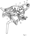
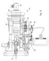
- the automatic train coupling has a coupling head 1, which comprises a coupling head housing 2 and the coupling lock 3.
- the coupling lock 3 is designed as a rotary lock, with the frog 6, to which a coupling eye 5 is connected so as to be rotatable about a coupling eye axis 8.
- the frog 6, in turn, is rotatable about the main axis 7.
- the frog 6 is mounted on a main bolt 19 and connected to it in a rotationally fixed manner.
- an actuator of a valve (not shown in detail here) of a compressed air line, in particular a brake air line HL, can be controlled via the main bolt 19, so that when the When the dome closure 3 is turned into the coupled position the valve is opened and when the dome closure 3 is turned into the uncoupled position the valve is closed.
- the coupling eye 5 has a first end 5.1, at which it is rotatably connected to the frog 6, and an opposite second end 5.2, which can be clamped into a mouth 9 of the frog 6 of an oppositely identical coupling head 1 in order to mechanically lock the two coupling heads 1 together. Accordingly, the coupling eye 5 has a crossbar (not shown in detail here) at its second end 5.2.
- each coupling head 1 can be rotated from the uncoupled position into the coupled position against the force of a spring accumulator 4, which is formed, for example, by one or more tension springs.
- FIG. 1 A decoupled position of the coupling head 1 or the coupling lock 3 is shown.
- Such a decoupled position which is also referred to as the ready-to-couple position, can also be the overdrawn position mentioned above.
- the dome closures 3 are loaded exclusively by tensile forces, whereas the compressive forces are transmitted via the end faces 23 of the end plate 24.
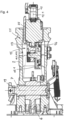
- the Figure 4 shows the arrangement from the Figure 3 again in a vertical section, but here without the coupling rod 10, which is connected in the axial direction to the coupling head housing 2.
- the electric motor 12 is connected in the drive connection to the frog 6 by a harmonic drive (or generally a reduction gear, in particular an eccentric gear or differential gear) 25, which carries a drive pinion 13 on the output side coaxial with the output rotational axis 12.1 of the electric motor, which drive pinion meshes with a crown gear 14 rotating about a vertical rotational axis 14.1 in order to drive the crown gear 14.
- the rotational axis 14.1 is parallel to the main axis 7, about which the main pin 19 can be rotated together with the frog 6.
- the output rotational axis 12.1 is arranged radially to the main axis 7.
- meshing bevel gears can also be considered to form a bevel gear
- the drive pinion 13 and the crown gear 14 together form an angular gear 15, which preferably has a reduction gear, as does the wave gear 25.
- the angular gear output 15.1 is formed by a rotary lever 17, which can be rotated about the angular gear output rotation axis 15.2.
- the angular gear output rotation axis 15.2 and the rotation axis 14.1 of the crown gear 14 coincide.
- the rotary lever 17 With the rotation of the crown gear 14, the rotary lever 17 is also rotated about the angular gear output rotation axis 15.2.
- the rotary lever 17 is connected to the frog 6 via an articulated lever 16, comprising a first lever part 16.1 and a second lever part 16.2.
- the first lever part 16.1 is articulated to the frog 6
- the second lever part 16.2 is articulated to the first lever part 16.1 and articulated to the rotary lever 17.
- the position of the rotary lever 17 can be detected, for example, by a sensor 18.
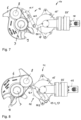
- the function of the electrically operated uncoupling device 11 will be explained below using the Figures 6 to 8 be explained.
- the frog 6 is shown in the uncoupled position; the angular gear output 15.1, which is formed by the rotary lever 17, is in its so-called zero position, in which it does not hinder rotation of the frog 6 about the main axis 7.
- the first lever part 16.1 and the second lever part 16.2 are folded against each other or moved towards each other, i.e., they enclose a comparatively acute angle between them.
- the angular gear output 15.1 can remain in its zero position, and the increasing distance between the connecting joint of the articulated lever 16 on the frog 6 and the connecting joint of the articulated lever 16 on the angular gear output 15.1 is bridged by folding apart the first lever part 16.1 and the second lever part 16.2. Accordingly, in the coupled position of the frog 6, the first lever part 16.1 and the second lever part 16.2 extend relatively linearly relative to one another.
- the angular gear output 15.1 or the rotary lever 17 is moved into the position shown in the Figure 8 shown release position by driving the electric motor 12. During this rotation, the rotary lever 17 pulls on the frog 6 via the articulated lever 16, so that it is rotated into the uncoupled position.
- the angle gear output 15.1 or the rotary lever 17 is turned again into its zero position, which is in the Figures 6 and 7 shown, preferably before the frog 6 begins to rotate into the coupled position.
- the Figure 9a shows the frog 6 in the coupled position and the angular gear output 15.1 in its zero position.
- the articulated lever 16 and the angular gear output 15.1 are designed differently from the embodiment shown in the previous figures.
- the articulated lever 16 is one-piece and is connected to the frog 6 in an articulated manner on the one hand and to the rotary lever 17 on the other hand.
- the rotary lever 17 on the angular gear output 15.1 is used to rotate the frog 6 from the position shown in the Figure 9a shown coupled position to the position shown in the Figure 9b shown uncoupled position by a Driver 34 is rotated in such a way that it pulls on the frog 6 via the articulated lever 16 to move it into the uncoupled position.
- angle gear output 15.1 is now returned to its zero position, which is in the Figures 9a and 9c shown, is rotated, this is done by turning back the driver 34, which is arranged non-rotatably on the angular gear output 15.1, so that it moves away from the rotary lever 17, which is arranged rotatably on the angular gear output 15.1, and, as shown in the Figure 9c As shown, a turning back of the frog 6 into the coupled position, during which turning back the rotary lever 17 must also be turned back via the articulated lever 16, is not blocked.
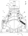
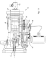
- FIG 10 A view from below of the coupling head housing 2 of an alternative design of an automatic train coupling is shown.
- the function of the automatic train coupling can be described in the Figure 1
- the coupling rod 10, which accommodates the electric motor 12, is shown in dashed lines.
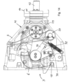
- parts of the electrically actuated uncoupling device 11 are arranged in a separate housing 31 below the coupling head housing 2. This is particularly evident from the Figure 11 Below the housing 31, parts of the manual operating device 20 are provided, which is connected to the main bolt 19 at the bottom. The parts of the manual operating device 20 can also be seen from the illustration in the Figure 14 , in which the components of the electrically operated decoupling device 11 are also shown.
- the angular gear output 15.1 which is rotatable about the angular gear output rotation axis 15.2, carries a first spur gear 29, which is connected to a spur gear segment 30 meshes, which is connected to the main pin 19 in a torque-transmitting manner, at least in the direction of rotation of the frog 6 from the coupled position to the uncoupled position.
- a one-sided torque transmission can be achieved by a freewheel.
- this torque transmission is achieved by a driver 32, which is fixedly connected to the spur gear segment 30 (or a corresponding second spur gear) and drives the lever 33 of the manual actuation device 20 when the angular gear output 15.1 is rotated from its zero position to the release position.
- the lever 33 is accordingly connected to the main pin 19 in a rotationally fixed manner. In principle, however, the connection of this lever 33 or another lever, which is driven by the driver 32, to the frog 6 would also be possible.
- the driver 32 acts unilaterally, it is easy to reverse the angular gear 15 without simultaneously moving the frog 6 into its coupled position.
- the frog remains in the uncoupled position until the coupling lock 3 is moved into the coupled position by engaging an opposing train coupler or an opposing coupling lock.
- another motor can also be considered instead of the electric motor, for example a hydraulic motor or a pneumatic motor.
Landscapes
- Engineering & Computer Science (AREA)
- Mechanical Engineering (AREA)
- Mechanical Operated Clutches (AREA)
- Gear Transmission (AREA)
Claims (17)
- Attelage ferroviaire automatique, en particulier pour un wagon de marchandises d'un véhicule ferroviaire, ayant une tête d'attelage (1), qui comprend un boîtier (2) de tête d'attelage et une fermeture d'accouplement (3) avec blocage,la fermeture d'accouplement (3) est réalisée sous forme de fermeture rotative avec un anneau d'attelage (5) et une pièce maîtresse (6), la pièce maîtresse (6) étant apte à tourner autour d'un axe principal (7) entre une position accouplée et une position désaccouplée, l'anneau d'attelage (5) étant raccordé à la pièce maîtresse (6) par une première extrémité (5.1) apte à tourner autour d'un axe (8) d'anneau d'attelage et présentant une deuxième extrémité libre (5.2) ; etla pièce maîtresse (6) présente une gueule (9) qui est agencée pour recevoir une deuxième extrémité (5.2) d'un anneau d'attelage (5) d'une tête d'attelage (1) opposée ; avec un dispositif de désaccouplement (11) actionné électriquement, hydrauliquement ou pneumatiquement, qui comprend un moteur électrique (12) ou un moteur hydraulique ou un moteur pneumatique, qui est raccordé au moins indirectement à la pièce maîtresse (6) par l'intermédiaire d'une liaison d'entraînement, afin de faire tourner la pièce maîtresse (6) de la position accouplée à la position désaccouplée ;caractérisé en ce quele dispositif de désaccouplement (11) présente une position de verrouillage dans laquelle il bloque une rotation de la pièce maîtresse (6) de la position désaccouplée à la position accouplée par l'intermédiaire de la liaison d'entraînement, un dispositif de commande (28) étant prévu, au moyen duquel le dispositif de désaccouplement (11) est apte à être commandé, afin de le maintenir en permanence en position de verrouillage pendant une période de temps.
- Attelage ferroviaire automatique selon la revendication 1, caractérisé en ce que le moteur, notamment le moteur électrique (12), présente un axe de rotation d'entraînement (12.1) qui est agencé au moins sensiblement radialement par rapport à l'axe principal (7).
- Attelage ferroviaire automatique selon l'une des revendications 1 ou 2, caractérisé en ce qu'une transmission angulée (15) est prévue dans la liaison d'entraînement entre le moteur, notamment le moteur électrique (12), et la pièce maîtresse (6).
- Attelage ferroviaire automatique selon la revendication 3, caractérisé en ce que l'axe de rotation d'entraînement (12.1) comporte un pignon d'entraînement (13) ou est disposé coaxialement à celui-ci, et l'entraîne, ce pignon étant en prise dentée avec une couronne dentée (14) ou un pignon conique dont l'axe de rotation (14.1) est parallèle à l'axe principal (7) pour former la transmission angulée (15).
- Attelage ferroviaire automatique selon l'une des revendications 3 ou 4, caractérisé en ce qu'entre le moteur, notamment le moteur électrique (12), et la transmission angulée (15) est agencé un réducteur, notamment sous la forme d'un engrenage excentrique, notamment d'un engrenage ondulé (25), agencé coaxialement à l'axe de rotation d'entraînement (12.1).
- Attelage ferroviaire automatique selon l'une des revendications 3 à 5, caractérisé en ce que la transmission angulée (15) est raccordée à la pièce maîtresse (6) par un levier articulé (16), le levier articulé (16) étant au moins en deux parties, comprenant une première partie de levier (16.1), qui est raccordée de manière articulée à la pièce maîtresse (6), et une deuxième partie de levier (16.2), qui est raccordée de manière articulée à la première partie de levier (16.1) et de manière articulée à une sortie (15.1) de transmission angulée, les axes de rotation des raccords articulés étant parallèles à l'axe principal (7).
- Attelage ferroviaire automatique selon la revendication 6, caractérisé en ce que la sortie (15.1) de la transmission angulée est formée par un levier rotatif (17) qui s'étend radialement par rapport à un axe de rotation d'entraînement (15.2) de la transmission angulée.
- Attelage ferroviaire automatique selon l'une des revendications 3 à 5, caractérisé en ce que la transmission angulée (15) est raccordée à la pièce maîtresse (6) par un levier articulé (16), le levier articulé (16) étant en une ou plusieurs parties et la sortie (15) de la transmission angulée comprenant un organe d'entraînement (34) et un levier rotatif (17), le levier rotatif (17) étant raccordé de manière articulée au levier articulé (16) et étant en liaison active avec l'organe d'entraînement (34), afin d'entraîner le levier rotatif (17) pour la rotation de la pièce maîtresse (6) de la position accouplée à la position désaccouplée et d'empêcher une rotation de la sortie (15.1) de la transmission angulée dans le sens opposé à celle-ci pour libérer le levier rotatif (17).
- Attelage ferroviaire automatique selon l'une des revendications 6 à 8, caractérisé en ce que la sortie (15.1) de transmission angulée est apte à être tournée autour d'un axe de rotation d'entraînement (15.2) de la transmission angulée entre une position zéro et une position de libération, et la longueur du levier articulé (16), en particulier les longueurs de la première partie de levier (16.1) et de la deuxième partie de levier (16.2), sont choisies de telle sorte que la pièce maîtresse (6) puisse être tournée de la position désaccouplée à la position accouplée, la sortie (15.1) de la transmission angulée restant dans la position zéro.
- Attelage ferroviaire automatique selon l'une des revendications 3 à 5, caractérisé en ce que la transmission angulée (15) est raccordée au moins indirectement, par l'intermédiaire d'une transmission par engrenages, à une broche principale (19) qui est raccordée à la pièce maîtresse (6) en une liaison d'entraînement.
- Attelage ferroviaire automatique selon la revendication 10, caractérisé en ce que la transmission angulée (15) comporte une sortie (15.1) de transmission angulée apte à tourner autour d'un axe de rotation d'entraînement (15.2) de transmission angulée qui est parallèle à l'axe principal (7) et sur lequel est agencé un premier pignon droit (29) qui engrène avec un deuxième pignon droit ou un segment de pignon droit (30) qui est en entraînement rotatif avec la broche principale (19), la sortie (15.1) de la transmission angulée étant apte à être tournée entre une position zéro et une position de libération.
- Attelage ferroviaire automatique selon l'une des revendications 1 à 11, caractérisé en ce qu'il est prévu un dispositif (20) d'actionnement manuel permettant de placer manuellement la pièce maîtresse (6) dans la position désaccouplée et/ou la sortie (15.1) de transmission angulée dans la position zéro.
- Attelage ferroviaire automatique selon les revendications 11 et 12, caractérisé en ce que le deuxième pignon droit ou segment de pignon droit (30) présente un organe d'entraînement (32) qui sollicite unilatéralement un levier (33) du dispositif (20) d'actionnement manuel, qui agit sur la broche principale (19), dans le sens d'une rotation de la pièce maîtresse (6) de la position accouplée à la position désaccouplée.
- Attelage ferroviaire automatique selon l'une des revendications 1 à 13, caractérisé en ce qu'il est prévu au moins un capteur (18) qui détecte une position du dispositif de désaccouplement (11), en particulier de la sortie (15.1) de la transmission angulée et/ou du levier articulé (16) et/ou du deuxième pignon droit ou du segment de pignon droit (30).
- Véhicule ferroviaire équipé d'un attelage automatique selon l'une des revendications 1 à 14.
- Procédé de désaccouplement d'un attelage ferroviaire automatique selon l'une des revendications 1 à 15, dans lequel la pièce maîtresse (6) est tournée depuis la position accouplée jusqu'à la position désaccouplée, par l'intermédiaire de la liaison d'entraînement, en entraînant le moteur, notamment le moteur électrique (12), au moyen du dispositif de désaccouplement (11) actionné électriquement, hydrauliquement ou pneumatiquement,
caractérisé en ce que
dans un mode de fonctionnement présélectionnable, le dispositif de désaccouplement (11) est maintenu dans la position de verrouillage, et une rotation de la pièce maîtresse (6) de la position désaccouplée à la position accouplée est bloquée par le dispositif de désaccouplement (11). - Procédé selon la revendication 16, caractérisé en ce qu'un premier mode de fonctionnement peut être réglé au moyen du dispositif de commande (28), dans lequel le dispositif de désaccouplement (11) libère à nouveau une rotation de la pièce maîtresse (6) depuis la position désaccouplée jusqu'à la position accouplée au moyen du dispositif de désaccouplement (11), immédiatement après la rotation de la pièce maîtresse (6), en particulier par rotation de la sortie (15.1) de la transmission angulée depuis la position de libération jusqu'à la position zéro, et un deuxième mode de fonctionnement peut être réglé au moyen du dispositif de commande (28), dans lequel le dispositif de désaccouplement (11) est maintenu dans la position de verrouillage.
Applications Claiming Priority (3)
| Application Number | Priority Date | Filing Date | Title |
|---|---|---|---|
| DE102020133503 | 2020-12-15 | ||
| DE102021105364 | 2021-03-05 | ||
| PCT/EP2021/085650 WO2022129021A1 (fr) | 2020-12-15 | 2021-12-14 | Attelage ferroviaire automatique et procédé de désaccouplement d'un attelage ferroviaire automatique |
Publications (2)
| Publication Number | Publication Date |
|---|---|
| EP4263318A1 EP4263318A1 (fr) | 2023-10-25 |
| EP4263318B1 true EP4263318B1 (fr) | 2025-04-09 |
Family
ID=79287790
Family Applications (1)
| Application Number | Title | Priority Date | Filing Date |
|---|---|---|---|
| EP21839851.9A Active EP4263318B1 (fr) | 2020-12-15 | 2021-12-14 | Attelage ferroviaire automatique et procédé de désaccouplement d'un attelage ferroviaire automatique |
Country Status (6)
| Country | Link |
|---|---|
| EP (1) | EP4263318B1 (fr) |
| CN (1) | CN116568581B (fr) |
| DE (1) | DE102021132991A1 (fr) |
| HU (1) | HUE071977T2 (fr) |
| PL (1) | PL4263318T3 (fr) |
| WO (1) | WO2022129021A1 (fr) |
Families Citing this family (17)
| Publication number | Priority date | Publication date | Assignee | Title |
|---|---|---|---|---|
| DE102022118360A1 (de) | 2022-07-22 | 2024-01-25 | Voith Patent Gmbh | Automatische Zugkupplung, Schienenfahrzeug mit einer automatischen Zugkupplung und Verfahren zum Kuppeln und Entkuppeln einer automatischen Zugkupplung |
| WO2024037882A1 (fr) | 2022-08-15 | 2024-02-22 | Voith Patent Gmbh | Élément de fermeture mécanique d'accouplement par traction et accouplement par traction comportant un tel élément de fermeture mécanique d'accouplement par traction |
| EP4339060B1 (fr) | 2022-09-16 | 2025-06-04 | Ovalo GmbH | Tête d'attelage à accouplement automatique de type scharfenberg |
| DE102022123887A1 (de) | 2022-09-19 | 2024-03-21 | Voith Patent Gmbh | Automatische Zugkupplung |
| DE102022125255A1 (de) * | 2022-09-30 | 2024-04-04 | Voith Patent Gmbh | Verfahren zum auflösen und neuzusammenstellen eines zugverbunds, automatische zugkupplung sowie zugverbund |
| EP4683843A1 (fr) | 2023-03-21 | 2026-01-28 | Voith Patent GmbH | Couplage de train automatique |
| DE102023111391A1 (de) | 2023-05-03 | 2024-11-07 | Voith Patent Gmbh | Automatische Zugkupplung |
| DE102023115258A1 (de) * | 2023-06-12 | 2024-12-12 | Knorr-Bremse Systeme für Schienenfahrzeuge GmbH | Mittelpufferkupplung für ein Schienenfahrzeug und Schienenfahrzeug mit einer solchen Mittelpufferkupplung |
| DE102023117027A1 (de) * | 2023-06-28 | 2025-01-02 | Knorr-Bremse Systeme für Schienenfahrzeuge GmbH | Verfahren zum Erfassen eines vollständigen Entkupplungsvorgangs einer Mittelpufferkupplung eines Schienenfahrzeugs, Mittelpufferkupplung für ein Schienenfahrzeug und Schienenfahrzeug mit einer solchen Mittelpufferkupplung |
| DE102023118506A1 (de) * | 2023-07-13 | 2025-01-16 | Knorr-Bremse Systeme für Schienenfahrzeuge GmbH | Digitale Automatische Kupplung (DAK) mit einem integrierten Antrieb für einen elektromechanischen Aktuator für ein Schienenfahrzeug und Schienenfahrzeug mit einer solchen Kupplung |
| DE102023120894A1 (de) * | 2023-08-07 | 2025-02-13 | Voith Patent Gmbh | Automatische Zugkupplung, insbesondere Mittelpufferkupplung, eine Kupplungsanordnung sowie ein Verfahren zum Auslösen einer Notbremsung |
| DE102023129402A1 (de) * | 2023-10-25 | 2025-04-30 | Pj Monitoring Gmbh | Automatische zugkupplung und verfahren zum überwachen und auflösen eines zugverbunds |
| DE102024104450A1 (de) * | 2024-02-16 | 2025-08-21 | Voith Patent Gmbh | Automatische zugkupplung sowie verfahren zum betreiben einer automatischen zugkupplung |
| EP4613603A1 (fr) | 2024-03-05 | 2025-09-10 | Dellner Couplers AB | Dispositif d'attelage pour un véhicule ferroviaire |
| EP4656489A1 (fr) | 2024-05-31 | 2025-12-03 | Dellner Couplers AB | Dispositif d'attelage pour un véhicule ferroviaire |
| DE102024126939A1 (de) * | 2024-09-19 | 2026-03-19 | Voith Patent Gmbh | Kupplungsanordnung und Luftkupplung für eine Kupplungsanordnung |
| CN120739999B (zh) * | 2025-09-02 | 2025-12-26 | 山西华图测绘科技有限公司 | 地质勘测用多地形的三脚架 |
Citations (10)
| Publication number | Priority date | Publication date | Assignee | Title |
|---|---|---|---|---|
| GB448876A (en) | 1933-12-18 | 1936-06-17 | Scharfenbergkupplung Ag | Automatic coupling for vehicles |
| DE1953105A1 (de) | 1969-10-22 | 1971-04-29 | Knorr Bremse Kg | Vorrichtung zum selektiven Entkuppeln von mit selbsttaetig kuppelbaren Kupplungen versehenen Schienenfahrzeugen |
| EP0578037A1 (fr) | 1992-07-09 | 1994-01-12 | Linke-Hofmann-Busch GmbH | Dispositif de commande pour un attelage à tampon central pour véhicules ferroviaires avec frein à air comprimé à action indirecte |
| WO1995011826A1 (fr) | 1993-10-29 | 1995-05-04 | Siemens Aktiengesellschaft | Dispositif permettant de rendre un vehicule de chemin de fer apte a etre attele ou detele |
| US5503280A (en) | 1994-04-26 | 1996-04-02 | Westinghouse Air Brake Company | Timed thrust uncoupling mechanism for passenger transit type railway cars |
| EP0711697A1 (fr) | 1994-11-09 | 1996-05-15 | Siemens Aktiengesellschaft | Dispositif pour établir la disponibilité pour rouler par gravité et/ou accoupler des véhicules guidés sur une voie |
| EP1149751A1 (fr) | 2000-04-26 | 2001-10-31 | Knorr-Bremse Systeme für Schienenfahrzeuge GmbH | Dispositif d' actionnement d' un adaptateur de longueur et/ou d' un dispositif de verrouillage d' un attelage automatique |
| EP2420427A2 (fr) | 2010-08-16 | 2012-02-22 | ALSTOM Transport SA | Procédé et dispositif de surveillance de l'état de fonctionnement d'un dispositif d'embrayage |
| EP3476688A1 (fr) | 2017-04-18 | 2019-05-01 | Qingdao Sri Technology Co., Ltd. | Mécanisme de commande de dételage d'attelage |
| DE102019101996A1 (de) | 2019-01-28 | 2020-07-30 | Voith Patent Gmbh | Zugkupplungshälfte und Verfahren zum Erfassen einer Drehposition des Hauptbolzens einer Zugkupplungshälfte |
Family Cites Families (8)
| Publication number | Priority date | Publication date | Assignee | Title |
|---|---|---|---|---|
| DE2923195A1 (de) | 1979-06-08 | 1980-12-18 | Scharfenbergkupplung Gmbh | Entkuppeleinrichtung fuer mittelpufferkupplungen an schienenfahrzeugen |
| DE3144730A1 (de) * | 1981-11-11 | 1983-05-19 | Scharfenbergkupplung Gmbh, 3320 Salzgitter | Mechanische mittelpufferkupplung |
| DE4013493C2 (de) * | 1990-04-27 | 1996-07-18 | Scharfenbergkupplung Gmbh | Kuppel- und Entkuppeleinrichtung für eine elektrische Kabelkupplung und eine mechanische Mittelpufferkupplung für Schienenfahrzeuge |
| DE4013521C2 (de) | 1990-04-27 | 1996-09-19 | Scharfenbergkupplung Gmbh | Kuppel- und Entkuppeleinrichtung für eine elektrische Kabelkupplung und eine mechanische Mittelpufferkupplung für Schienenfahrzeuge |
| CN102126505B (zh) * | 2011-03-17 | 2013-03-20 | 中国神华能源股份有限公司 | 一种车钩开启装置 |
| DE102016210278B4 (de) * | 2016-06-10 | 2024-03-28 | Voith Patent Gmbh | Kuppel- und Entkuppelvorrichtung für Schienenfahrzeuge |
| CN106274958B (zh) | 2016-08-31 | 2018-02-02 | 中车青岛四方车辆研究所有限公司 | 车钩自动解钩机构 |
| DE102019102455A1 (de) * | 2019-01-31 | 2020-08-06 | Voith Patent Gmbh | Automatische Zugkupplung |
-
2021
- 2021-12-14 HU HUE21839851A patent/HUE071977T2/hu unknown
- 2021-12-14 CN CN202180082674.9A patent/CN116568581B/zh active Active
- 2021-12-14 PL PL21839851.9T patent/PL4263318T3/pl unknown
- 2021-12-14 DE DE102021132991.4A patent/DE102021132991A1/de active Pending
- 2021-12-14 WO PCT/EP2021/085650 patent/WO2022129021A1/fr not_active Ceased
- 2021-12-14 EP EP21839851.9A patent/EP4263318B1/fr active Active
Patent Citations (10)
| Publication number | Priority date | Publication date | Assignee | Title |
|---|---|---|---|---|
| GB448876A (en) | 1933-12-18 | 1936-06-17 | Scharfenbergkupplung Ag | Automatic coupling for vehicles |
| DE1953105A1 (de) | 1969-10-22 | 1971-04-29 | Knorr Bremse Kg | Vorrichtung zum selektiven Entkuppeln von mit selbsttaetig kuppelbaren Kupplungen versehenen Schienenfahrzeugen |
| EP0578037A1 (fr) | 1992-07-09 | 1994-01-12 | Linke-Hofmann-Busch GmbH | Dispositif de commande pour un attelage à tampon central pour véhicules ferroviaires avec frein à air comprimé à action indirecte |
| WO1995011826A1 (fr) | 1993-10-29 | 1995-05-04 | Siemens Aktiengesellschaft | Dispositif permettant de rendre un vehicule de chemin de fer apte a etre attele ou detele |
| US5503280A (en) | 1994-04-26 | 1996-04-02 | Westinghouse Air Brake Company | Timed thrust uncoupling mechanism for passenger transit type railway cars |
| EP0711697A1 (fr) | 1994-11-09 | 1996-05-15 | Siemens Aktiengesellschaft | Dispositif pour établir la disponibilité pour rouler par gravité et/ou accoupler des véhicules guidés sur une voie |
| EP1149751A1 (fr) | 2000-04-26 | 2001-10-31 | Knorr-Bremse Systeme für Schienenfahrzeuge GmbH | Dispositif d' actionnement d' un adaptateur de longueur et/ou d' un dispositif de verrouillage d' un attelage automatique |
| EP2420427A2 (fr) | 2010-08-16 | 2012-02-22 | ALSTOM Transport SA | Procédé et dispositif de surveillance de l'état de fonctionnement d'un dispositif d'embrayage |
| EP3476688A1 (fr) | 2017-04-18 | 2019-05-01 | Qingdao Sri Technology Co., Ltd. | Mécanisme de commande de dételage d'attelage |
| DE102019101996A1 (de) | 2019-01-28 | 2020-07-30 | Voith Patent Gmbh | Zugkupplungshälfte und Verfahren zum Erfassen einer Drehposition des Hauptbolzens einer Zugkupplungshälfte |
Also Published As
| Publication number | Publication date |
|---|---|
| DE102021132991A1 (de) | 2022-06-15 |
| CN116568581A (zh) | 2023-08-08 |
| HUE071977T2 (hu) | 2025-10-28 |
| CN116568581B (zh) | 2026-02-27 |
| WO2022129021A1 (fr) | 2022-06-23 |
| EP4263318A1 (fr) | 2023-10-25 |
| PL4263318T3 (pl) | 2025-09-01 |
Similar Documents
| Publication | Publication Date | Title |
|---|---|---|
| EP4263318A1 (fr) | Attelage ferroviaire automatique et procédé de désaccouplement d'un attelage ferroviaire automatique | |
| EP4263319B1 (fr) | Attelage de traction automatique | |
| EP4330110B1 (fr) | Attelage automatique de traction et procédé de dételage d'un attelage automatique de traction | |
| EP4330109B1 (fr) | Accouplement de traction automatique et procédé de désaccouplement d'un accouplement de traction automatique | |
| EP3689705B1 (fr) | Attelage automatique de trains | |
| EP1557298B2 (fr) | Attelage de remorque | |
| EP3382103B1 (fr) | Système de raccord rapide | |
| DE102009018188B4 (de) | Vorrichtung zum automatischen Schließen einer Fahrzeugtür | |
| EP2036421B1 (fr) | Dispositif de couplage d'un arbre de transmission avec la prise de force d'un tracteur | |
| EP4486624B1 (fr) | Accouplement de train automatique, véhicule guidé sur rail comprenant un tel accouplement de train automatique, et procédé de désaccouplement de deux accouplements de train automatiques qui sont accouplés l'un à l'autre | |
| EP3105100A1 (fr) | Tête de couplage d'un attelage automatique à tampon central | |
| DE3800767A1 (de) | Vorrichtung fuer die bewegung eines torblattes wahlweise mittels eines sicherheitsueberwachten motorantriebes oder eines antriebes von hand | |
| EP1956168B1 (fr) | Serrure de porte de véhicule automobile | |
| EP2371657A1 (fr) | Tête d'accouplement d'un attelage central automatique | |
| EP4558375A1 (fr) | Couplage de train automatique, véhicule ferroviaire doté d'un couplage de train automatique, et procédé de couplage et de découplage d'un couplage de train automatique | |
| EP0823342B1 (fr) | Attelage de remorque | |
| DE3042141C2 (fr) | ||
| DE9205034U1 (de) | Fahrzeugzug | |
| DE102023127092A1 (de) | Kupplungsanordnung, insbesondere Hybridkupplungsanordnung | |
| DE102023121378A1 (de) | Kupplungsanordnung, insbesondere Hybridkupplungsanordnung | |
| WO2025103971A1 (fr) | Accouplement de train automatique et ensemble d'accouplement | |
| WO2025119718A1 (fr) | Attelage de train automatique, dispositif de découplage pour un attelage de train automatique, et véhicule ferroviaire comprenant un attelage de train automatique | |
| WO2025125569A1 (fr) | Attelage automatique de train et ensemble d'attelage | |
| EP3782829A1 (fr) | Mécanisme de verrouillage pour un embrayage à bille | |
| DE3234187A1 (de) | Betaetigungsvorrichtung fuer eine blockiereinrichtung an riegelgetrieben |
Legal Events
| Date | Code | Title | Description |
|---|---|---|---|
| STAA | Information on the status of an ep patent application or granted ep patent |
Free format text: STATUS: UNKNOWN |
|
| STAA | Information on the status of an ep patent application or granted ep patent |
Free format text: STATUS: THE INTERNATIONAL PUBLICATION HAS BEEN MADE |
|
| PUAI | Public reference made under article 153(3) epc to a published international application that has entered the european phase |
Free format text: ORIGINAL CODE: 0009012 |
|
| STAA | Information on the status of an ep patent application or granted ep patent |
Free format text: STATUS: REQUEST FOR EXAMINATION WAS MADE |
|
| 17P | Request for examination filed |
Effective date: 20230717 |
|
| AK | Designated contracting states |
Kind code of ref document: A1 Designated state(s): AL AT BE BG CH CY CZ DE DK EE ES FI FR GB GR HR HU IE IS IT LI LT LU LV MC MK MT NL NO PL PT RO RS SE SI SK SM TR |
|
| DAV | Request for validation of the european patent (deleted) | ||
| DAX | Request for extension of the european patent (deleted) | ||
| GRAP | Despatch of communication of intention to grant a patent |
Free format text: ORIGINAL CODE: EPIDOSNIGR1 |
|
| STAA | Information on the status of an ep patent application or granted ep patent |
Free format text: STATUS: GRANT OF PATENT IS INTENDED |
|
| INTG | Intention to grant announced |
Effective date: 20241105 |
|
| GRAS | Grant fee paid |
Free format text: ORIGINAL CODE: EPIDOSNIGR3 |
|
| GRAA | (expected) grant |
Free format text: ORIGINAL CODE: 0009210 |
|
| STAA | Information on the status of an ep patent application or granted ep patent |
Free format text: STATUS: THE PATENT HAS BEEN GRANTED |
|
| P01 | Opt-out of the competence of the unified patent court (upc) registered |
Free format text: CASE NUMBER: APP_7002/2025 Effective date: 20250211 |
|
| AK | Designated contracting states |
Kind code of ref document: B1 Designated state(s): AL AT BE BG CH CY CZ DE DK EE ES FI FR GB GR HR HU IE IS IT LI LT LU LV MC MK MT NL NO PL PT RO RS SE SI SK SM TR |
|
| REG | Reference to a national code |
Ref country code: GB Ref legal event code: FG4D Free format text: NOT ENGLISH |
|
| REG | Reference to a national code |
Ref country code: CH Ref legal event code: EP |
|
| REG | Reference to a national code |
Ref country code: DE Ref legal event code: R096 Ref document number: 502021007197 Country of ref document: DE |
|
| REG | Reference to a national code |
Ref country code: IE Ref legal event code: FG4D Free format text: LANGUAGE OF EP DOCUMENT: GERMAN |
|
| REG | Reference to a national code |
Ref country code: SE Ref legal event code: TRGR |
|
| REG | Reference to a national code |
Ref country code: NL Ref legal event code: MP Effective date: 20250409 |
|
| PG25 | Lapsed in a contracting state [announced via postgrant information from national office to epo] |
Ref country code: NL Free format text: LAPSE BECAUSE OF FAILURE TO SUBMIT A TRANSLATION OF THE DESCRIPTION OR TO PAY THE FEE WITHIN THE PRESCRIBED TIME-LIMIT Effective date: 20250409 |
|
| PG25 | Lapsed in a contracting state [announced via postgrant information from national office to epo] |
Ref country code: FI Free format text: LAPSE BECAUSE OF FAILURE TO SUBMIT A TRANSLATION OF THE DESCRIPTION OR TO PAY THE FEE WITHIN THE PRESCRIBED TIME-LIMIT Effective date: 20250409 Ref country code: PT Free format text: LAPSE BECAUSE OF FAILURE TO SUBMIT A TRANSLATION OF THE DESCRIPTION OR TO PAY THE FEE WITHIN THE PRESCRIBED TIME-LIMIT Effective date: 20250811 Ref country code: ES Free format text: LAPSE BECAUSE OF FAILURE TO SUBMIT A TRANSLATION OF THE DESCRIPTION OR TO PAY THE FEE WITHIN THE PRESCRIBED TIME-LIMIT Effective date: 20250409 |
|
| REG | Reference to a national code |
Ref country code: LT Ref legal event code: MG9D |
|
| PG25 | Lapsed in a contracting state [announced via postgrant information from national office to epo] |
Ref country code: GR Free format text: LAPSE BECAUSE OF FAILURE TO SUBMIT A TRANSLATION OF THE DESCRIPTION OR TO PAY THE FEE WITHIN THE PRESCRIBED TIME-LIMIT Effective date: 20250710 Ref country code: NO Free format text: LAPSE BECAUSE OF FAILURE TO SUBMIT A TRANSLATION OF THE DESCRIPTION OR TO PAY THE FEE WITHIN THE PRESCRIBED TIME-LIMIT Effective date: 20250709 |
|
| PG25 | Lapsed in a contracting state [announced via postgrant information from national office to epo] |
Ref country code: BG Free format text: LAPSE BECAUSE OF FAILURE TO SUBMIT A TRANSLATION OF THE DESCRIPTION OR TO PAY THE FEE WITHIN THE PRESCRIBED TIME-LIMIT Effective date: 20250409 |
|
| PG25 | Lapsed in a contracting state [announced via postgrant information from national office to epo] |
Ref country code: HR Free format text: LAPSE BECAUSE OF FAILURE TO SUBMIT A TRANSLATION OF THE DESCRIPTION OR TO PAY THE FEE WITHIN THE PRESCRIBED TIME-LIMIT Effective date: 20250409 |
|
| PG25 | Lapsed in a contracting state [announced via postgrant information from national office to epo] |
Ref country code: RS Free format text: LAPSE BECAUSE OF FAILURE TO SUBMIT A TRANSLATION OF THE DESCRIPTION OR TO PAY THE FEE WITHIN THE PRESCRIBED TIME-LIMIT Effective date: 20250709 |
|
| PG25 | Lapsed in a contracting state [announced via postgrant information from national office to epo] |
Ref country code: IS Free format text: LAPSE BECAUSE OF FAILURE TO SUBMIT A TRANSLATION OF THE DESCRIPTION OR TO PAY THE FEE WITHIN THE PRESCRIBED TIME-LIMIT Effective date: 20250809 |
|
| REG | Reference to a national code |
Ref country code: HU Ref legal event code: AG4A Ref document number: E071977 Country of ref document: HU |
|
| PG25 | Lapsed in a contracting state [announced via postgrant information from national office to epo] |
Ref country code: LV Free format text: LAPSE BECAUSE OF FAILURE TO SUBMIT A TRANSLATION OF THE DESCRIPTION OR TO PAY THE FEE WITHIN THE PRESCRIBED TIME-LIMIT Effective date: 20250409 |
|
| REG | Reference to a national code |
Ref country code: CH Ref legal event code: U11 Free format text: ST27 STATUS EVENT CODE: U-0-0-U10-U11 (AS PROVIDED BY THE NATIONAL OFFICE) Effective date: 20260101 |
|
| PGFP | Annual fee paid to national office [announced via postgrant information from national office to epo] |
Ref country code: DE Payment date: 20251211 Year of fee payment: 5 |
|
| REG | Reference to a national code |
Ref country code: DE Ref legal event code: R026 Ref document number: 502021007197 Country of ref document: DE |
|
| PG25 | Lapsed in a contracting state [announced via postgrant information from national office to epo] |
Ref country code: DK Free format text: LAPSE BECAUSE OF FAILURE TO SUBMIT A TRANSLATION OF THE DESCRIPTION OR TO PAY THE FEE WITHIN THE PRESCRIBED TIME-LIMIT Effective date: 20250409 Ref country code: SM Free format text: LAPSE BECAUSE OF FAILURE TO SUBMIT A TRANSLATION OF THE DESCRIPTION OR TO PAY THE FEE WITHIN THE PRESCRIBED TIME-LIMIT Effective date: 20250409 |
|
| PGFP | Annual fee paid to national office [announced via postgrant information from national office to epo] |
Ref country code: AT Payment date: 20260113 Year of fee payment: 5 |
|
| PGFP | Annual fee paid to national office [announced via postgrant information from national office to epo] |
Ref country code: HU Payment date: 20251223 Year of fee payment: 5 Ref country code: FR Payment date: 20251229 Year of fee payment: 5 |
|
| PLBI | Opposition filed |
Free format text: ORIGINAL CODE: 0009260 |
|
| PGFP | Annual fee paid to national office [announced via postgrant information from national office to epo] |
Ref country code: SE Payment date: 20251219 Year of fee payment: 5 |
|
| PG25 | Lapsed in a contracting state [announced via postgrant information from national office to epo] |
Ref country code: CZ Free format text: LAPSE BECAUSE OF FAILURE TO SUBMIT A TRANSLATION OF THE DESCRIPTION OR TO PAY THE FEE WITHIN THE PRESCRIBED TIME-LIMIT Effective date: 20250409 |
|
| PLAX | Notice of opposition and request to file observation + time limit sent |
Free format text: ORIGINAL CODE: EPIDOSNOBS2 |
|
| REG | Reference to a national code |
Ref country code: CH Ref legal event code: L10 Free format text: ST27 STATUS EVENT CODE: U-0-0-L10-L00 (AS PROVIDED BY THE NATIONAL OFFICE) Effective date: 20260121 |
|
| PGFP | Annual fee paid to national office [announced via postgrant information from national office to epo] |
Ref country code: PL Payment date: 20251210 Year of fee payment: 5 |
|
| PG25 | Lapsed in a contracting state [announced via postgrant information from national office to epo] |
Ref country code: EE Free format text: LAPSE BECAUSE OF FAILURE TO SUBMIT A TRANSLATION OF THE DESCRIPTION OR TO PAY THE FEE WITHIN THE PRESCRIBED TIME-LIMIT Effective date: 20250409 |
|
| PG25 | Lapsed in a contracting state [announced via postgrant information from national office to epo] |
Ref country code: SK Free format text: LAPSE BECAUSE OF FAILURE TO SUBMIT A TRANSLATION OF THE DESCRIPTION OR TO PAY THE FEE WITHIN THE PRESCRIBED TIME-LIMIT Effective date: 20250409 |
|
| PG25 | Lapsed in a contracting state [announced via postgrant information from national office to epo] |
Ref country code: IT Free format text: LAPSE BECAUSE OF FAILURE TO SUBMIT A TRANSLATION OF THE DESCRIPTION OR TO PAY THE FEE WITHIN THE PRESCRIBED TIME-LIMIT Effective date: 20250409 |
|
| 26 | Opposition filed |
Opponent name: DELLNER COUPLERS AB Effective date: 20260109 |
|
| PG25 | Lapsed in a contracting state [announced via postgrant information from national office to epo] |
Ref country code: RO Free format text: LAPSE BECAUSE OF FAILURE TO SUBMIT A TRANSLATION OF THE DESCRIPTION OR TO PAY THE FEE WITHIN THE PRESCRIBED TIME-LIMIT Effective date: 20250409 |
|
| PGFP | Annual fee paid to national office [announced via postgrant information from national office to epo] |
Ref country code: CH Payment date: 20260101 Year of fee payment: 5 |